ELGi TS Series User manual
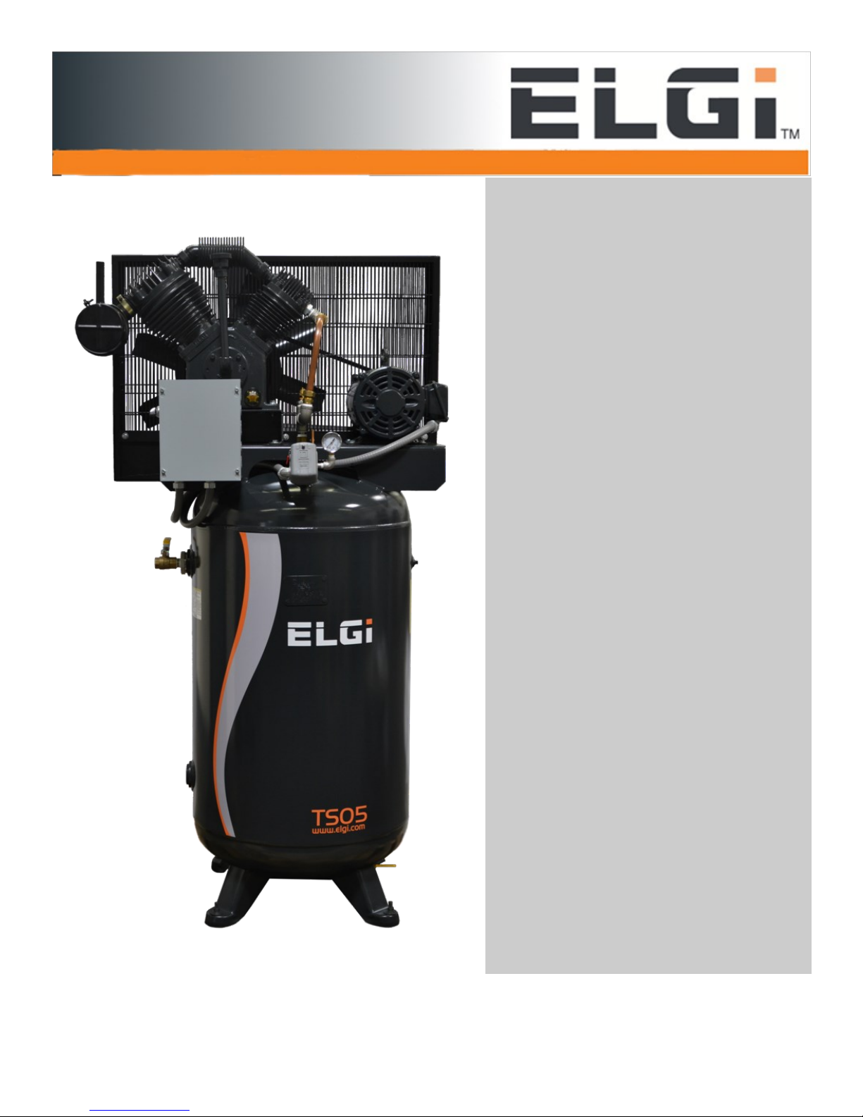
TS Series
TS05 to TS15
Two-Stage
Reciprocating
Air Compressor
OPERATION AND MAINTENANCE MANUAL

2
TS Series
Model Number:
Serial Number:
Date Purchased:
Purchased from:
For further technical assistance, service or replacement parts, please contact:
Elgi Compressors USA, Inc.
3201 South Boulevard
Charlotte, NC 28209
Phone: 704-943-7966
FAX: 704-944-8338
www.elgi.us
Please include the unit serial number located on the control panel with all inquiries.
Elgi reserves the right to make changes and improvements to update products sold previously
without notice or obligation.
Issue Date: August 17, 2017

3
TS Series
Table of Contents
Safety Precautions
1.0 General Information
2.0 Installation
2.1 Inspection Upon Receiving
2.2 Handling
2.3 Location
2.4 Space Requirements
2.5 Wiring
3.0 Control Panel
3.1 Wiring Schematics
4.0 Initial startup
5.0 Maintenance
5.1 Pressure Switch Adjustment
6.0 Trouble Shooting
7.0 Replacement System Parts 5 HP
7.1 Replacement Pump Parts 5 HP
8.0 Replacement System Parts 7.5 HP
8.1 Replacement Pump Parts 7.5 HP
9.0 Replacement System Parts 10 HP
9.1 Replacement Pump Parts 10 HP
10.0 Replacement System Parts 15 HP
10.1 Replacement Pump Parts 15 HP
Notes

4
TS Series
Safety Precautions
Pressurized air from the system may cause personnel injury or property damage if the unit is improp-
erly operated or maintained. The operator should have carefully read and become familiar with the
contents of this manual before installing, wiring, starting, operating, adjusting and maintaining the
system. The operator is expected to use common sense safety precautions, good workmanship
practices and follow any related local safety precautions.
In addition:
• Before starting any installation or maintenance procedures, disconnect all power to the
package.
• All electrical procedures must be in compliance with all national, state and local codes and re-
quirements.
• A certified electrician should connect all wiring.
• Refer to the electrical wiring diagram provided with the unit before starting any installation or
maintenance work.
• Release all pressure from the package before removing, loosening, or servicing any covers,
guards, fittings, connections, or other devices.
• Notify appropriate facility personnel if repairs or maintenance will affect available compressed air
levels.
• This is a high speed, rotating piece of machinery. Do not attempt to service any part while ma-
chine is in operation.
• Do not operate unit without belt guards, shields or screens in place.
• Make sure that all loose articles, packing material, and tools are clear of the package.
• Check all safety devices periodically for proper operation.
• Never operate a compressor with its relief valve not in place. Damage to the compressor may oc-
cur.
• Electrical service must be the same as specified on the control panel nameplate or damage to
the equipment may occur.
• Vibration during shipment can loosen electrical terminals, fuse inserts, and mechanical connec-
tions. Tighten as necessary.

5
TS Series
1.0 General Information
System Configurations
The Reciprocating Air systems are tank mounted units. All consist of at least one compressor, one
motor, integral pre-wired control panel and air receiver. The complete package is pre-wired, pre-
piped, and assembled.
Compressor Module
The compressor is a continuous duty rated lubricated reciprocating type. The design is two stage
and air cooled with finger type stainless steel valves. An oil splasher is fitted to the connecting rod to
lubricate all moving parts. The connecting rod and crankcase assembly is precision machined and
dynamically balanced. The crankshaft is forged out of carbon steel, hardened, and precision ground.
The crankshaft is provided with steel roller bearings and phosphor bronze bushings. The crankcase
is made of high grade cast iron. It acts as sump for the lubricating oil and is provided with a breather
drain plug and dipstick. The breather maintains a partial vacuum in the crankcase to facilitate better
breathing. The cylinders and cylinder heads are made of high grade cast iron and they have close
deep fins for effective cooling. The hardness of the cylinders is closely controlled to insure high wear
resistance. The pistons are automotive type made out of low expansion aluminum alloy. They are
provide with plain compression rings, stepped compression rings and slotted oil control rings. The
rings are made of special quality close grained cast iron and designed for controlling wear and keep-
ing oil consumption at a minimum. The wrist pins are made of chrome steel case hardened and pre-
cision ground. The intercooler is made of aluminum with fins for effective cooling.
Compressor Drive and Motor
The compressor is v-belt driven and protected by an OSHA approved totally enclosed belt guard. A
slotted mounting base allows full adjustment for belt tensioning. The motor is a NEMA rated, open
drip proof, with 1.15 service factor suitable for 208 or 230/460V electrical service.
Intake Filter
Each compressor is fitted with inlet air filters. The inlet filter removes dust from the incoming air
through an element.
Control System The mounted and wired control system is NEMA 1 and U.L. labeled. The . The
control panel also includes full voltage motor starters with overload protection, Off-On selector
switch and a pressure switch.
Air Receiver
The air receiver is ASME Coded, National Board Certified, and rated for a minimum 200 PSIG de-
sign pressure. The tank will include a safety relief valve, pressure gauge and manual drain valve.

6
TS Series
2.0 Installation
2.1 Inspection upon Receiving
The Reciprocating Air system should be carefully inspected upon delivery. Any damage by the carri-
er should be noted on the delivery receipt, especially if the system will not be immediately uncrated
and installed. The system may remain in its shipping container(s) until ready for installation. If the
system is to be stored prior to installation, it must be protected from the elements to prevent rust and
deterioration.
DO NOT REMOVE the protective covers from the inlet and discharge connection ports of the unit
until they are ready for connecting to the distribution system.
2.2 Handling
!!WARNING!!
USE APPROPRIATE LOAD RATED LIFTING EQUIPMENT AND OBSERVE SAFE LIFTING PRO-
CEDURES DURING ALL MOVES.
The compressor package can be moved with either a forklift or dollies. Keep all packing in place dur-
ing installation to minimize damage. Examine the route the unit must travel and note dimensions of
doorways and low ceilings. Units should be placed to ensure easy access to perform maintenance
and high visibility of indicators and gauges.
2.3 Location
The Air system should be installed indoors in a clean, well-ventilated environment. Areas of exces-
sive dust, dirt or other air-borne particulate should be avoided. Secure the package to a flat, level
surface capable of supporting the weight and forces of the unit. Make sure that the main base is not
bowed, twisted, or uneven. The tank must be securely bolted using all mounting holes provided in
the tank. If a raised concrete pad is used, the tank must not overhang the concrete pad. A method to
drain away moisture is necessary. If a gravity drain is not available, a connection to a drain is neces-
sary. The area should have a maximum ambient temperature of 113oF (45oC). (Note: At tempera-
tures below 32oF condensate can occur which could affect operation.)
2.4 Space Requirements
The Air system should be placed to ensure easy access to perform maintenance and high visibility
of indicators and gauges. It is recommended that a minimum space of 24” be allowed on all sides of
the compressor system for ventilation and maintenance. A minimum space of 36" in front of the con-
trol panel is required by NEC code. A vertical distance of 36” is required above the unit for ventilation
and maintenance.

7
TS Series
2.0 Installation (Continued)
2.5 Wiring
WARNING!
BE SURE TO DISCONNECT ALL ELECTRICAL POWER TO THE COMPRESSOR SYSTEM BE-
FORE PERFORMING ANY ELECTRICAL PROCEDURES.
Refer to the electrical diagram provided with the unit before starting any installation or
maintenance work. Do not operate compressor on a voltage other than the voltage specified
on the compressor nameplate. All customer wiring should be in compliance with the National
Electrical Code and any other applicable state or local codes.
Check the control voltage, phase, and amp ratings before starting the electrical installation, and
make sure the voltage supplied by the customer is the same.
The wire size should be able to handle peak motor amp load of all operating units, refer to the full
load and compressor system amperes on the wiring diagram.
Check all electrical connections within the air system that may have loosened during shipment.
Only qualified electricians should make power connections to the control panel and any intercon-
necting wiring.
If emergency generator is used for backup make sure the electrical supply is consistent with the air
system’s requirements.
If equipped with an emergency generator the three-phase power supplied must match that of the
normal supply to allow for correct direction of the motor rotation at all times.
If equipped with an emergency generator the three-phase power supplied must match that of the
normal supply to allow for correct direction of the motor rotation at all times.

8
TS Series
3.0 Control Panel
5 HP 208/3/60 230/3/60 460/3/60
Starter 30-03-408 30-03-417 30-03-036
Overload Relay 30-03-207 30-03-206 30-03-204
5 HP 208/1/60 230/1/60
Starter 30-03-410 30-03-420
Overload Relay 30-03-008 30-03-208
Off-On
Switch
54-17-009
Motor
Starter
(see chart)
Motor
Overload
(see chart)
10 HP 208/3/60 230/3/60 460/3/60
Starter 30-03-410 30-03-420 30-03-038
Overload Relay 30-03-208 30-03-208 30-03-206
7.5 HP 208/3/60 230/3/60 460/3/60
Starter 30-03-409 30-03-419 30-03-037
Overload Relay 30-03-208 30-03-207 30-03-205
15 HP 208/3/60 230/3/60 460/3/60
Starter 30-03-412 30-03-422 30-03-040
Overload Relay 30-03-210 30-03-209 30-03-207
9
TS Series
3.0 Control Panel
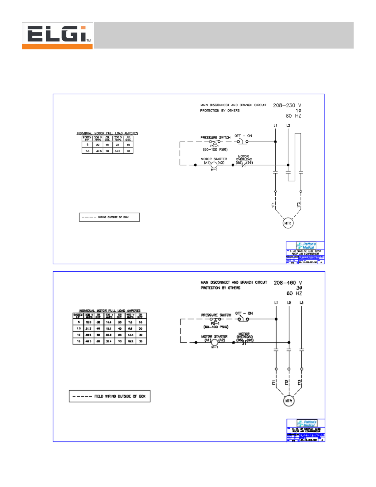
3.1 Wiring Schematics
Three Phase Compressors
Single Phase Compressors

10
TS Series
4.0 Initial Startup
Check for correct direction of rotation of compressor by momentarily turning the Off-On switch to the
“On” position and observing rotation.
WARNING:
DO NOT RUN THE COMPRESSOR BACKWARDS!
Rotation direction arrows are located on the belt guard (rotation is clockwise, facing the compressor
pulley). Correct the rotation, if required, by switching the motor leads at the starter.
Start compressor by turning the “Off-On” switch to the “On” position. Allow compressor to operate for
a short time (15 to 30 seconds) and check for any unusual noises or vibrations.
If everything appears normal, allow compressor to run in the “On” mode until pressure builds in the
air receiver. The compressor should stop when the pressure reading reaches 125 psig. Check for
any leaks in the piping. Repair leaks, if needed.
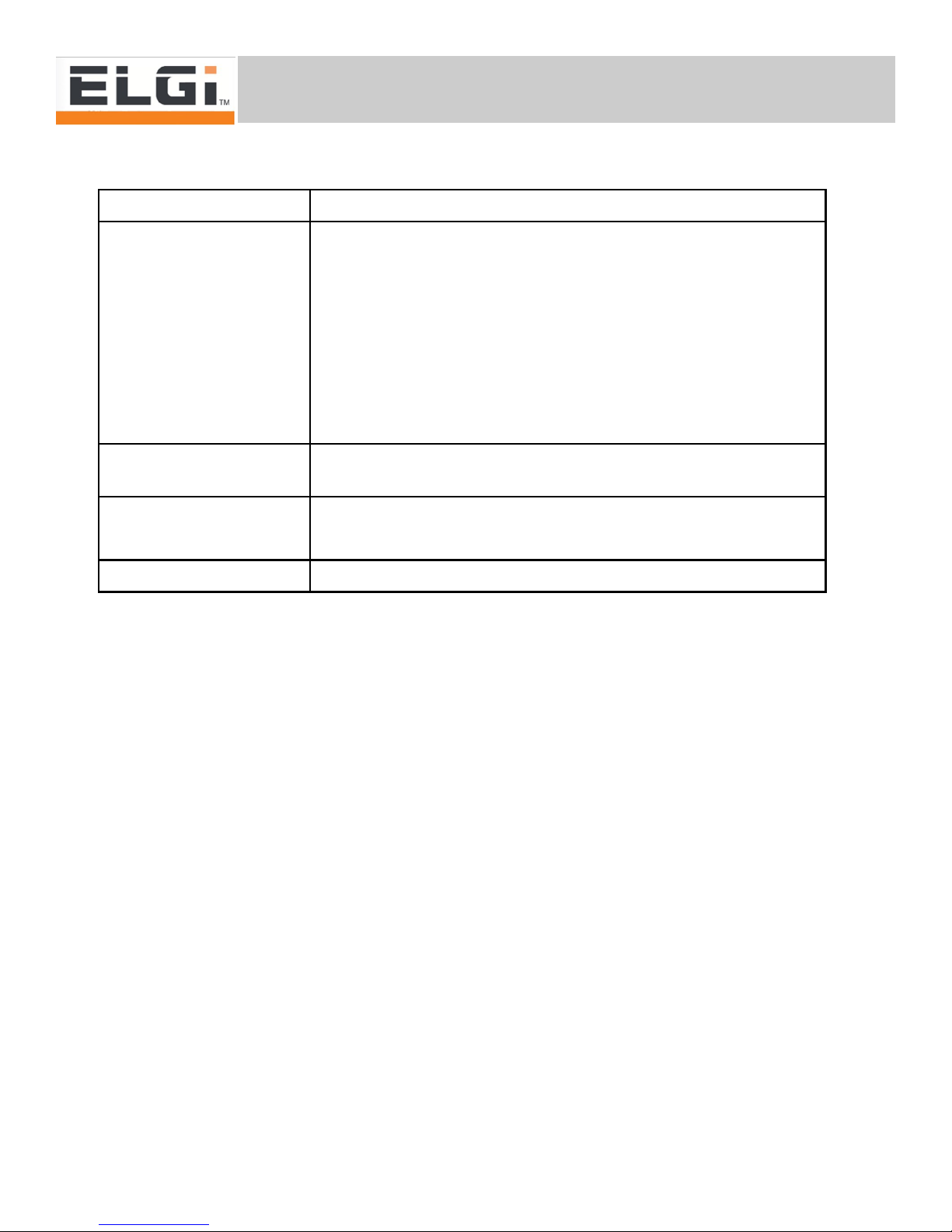
5.0 Maintenance
Frequency Maintenance Required
Daily or before
compressor starting
a) Check oil level
b) Drain condensate from air receiver
c) Check belt tension
150 Hours or 10 Days a) Relieve moisture and dirt from air receiver
b) Carry out first oil change
250 Hours or 20 Days
a) Check for unusual noise or vibration
b) Check bolts for tightness
c) Check for leaks
d) Check pressure settings
e) Check inlet air filter
a) Change Oil
500 Hours or 1 Month
b) Clean breather valve
c) Tighten all wires
d) Clean air filter element
11
TS Series
5.0 Maintenance (continued)
Maintenance
Daily or before compressor starting
• Remove dirt and dust from compressor.
• Check oil level in crankcase, replenish if needed.
• Check Belt tension.
• Drain condensate from air receiver.
150 hours or 10 days
• Drain condensate from receiver.
• Drain oil from compressor after running to warm oil, add new oil to compressor.
250 hours or 20 days
• Check for unusual noise or vibration.
• Check bolts for tightness.
• Check for air leaks in piping, cooler, safety valves and drain valves.
• Check pressure switch operation and settings.
• Remove inlet air filter and clean with compressed air, reassemble on compressor.
Frequency Maintenance Required
1000 Hours or 3 Months
a) Inspect valves
b) Check piping for leaks
c) Inspect check valve
d) Change inlet filter element
e) Change breather valve
f) Check pressure setting
g) Check bolts for tightness
2500 Hours or 1 Year a) Annual preventative maintenance kit with tune up kit
Clean coolers
a) Clean and test air receiver for leaks
2 Years b) Change safety valves
7500 hours or 3 Years a) Overhaul Compressor

12
TS Series
5.0 Maintenance (continued)
500 hours or 1 month
• The breather valve should be dismantled, cleaned and checked for seating on the diaphragm
and reassembled.
• Tighten all control and motor wires.
• Drain crankcase oil and refill with proper quantity and oil.
• Clean air filter element.
1000 hours or 3 months
• Remove the L.P cylinder heads. Dismantled the disc valves/Finger Valves. Remove carbon from
the valve discs, springs and valve plates.
• All the pipe lines should be checked for leaks at joints and replace packing's if necessary.
• Check tank check valve for leaking, replace if required.
• Change the air filter element.
2500 hours or 1 year
• Remove Carbon from the after cooler pipe (optional) and the intercooler by any one of the follow-
ing methods.
a) Heat the cooler to appropriate temperature at which the carbon scaling may disinter
grate from the inside walls of the cooler. Then hammer the after cooler with mallet to relieve
the carbon particles off the after cooler.
b) Immerse the cooler in hydrocarbon like Benzene or Toluene solution for a substantial
period of time. Then clean the after cooler with compressed air.
• Lubricate the electric motor bearings using a special grease gun or by removing the end covers.
• The compressor should be completely stripped off by experienced personnel. All parts have to be
thoroughly cleaned, examined and repair in a clean surrounding and rebuilt. Before
dismantling the unit, disconnect the power supply and release all the air from the air
receiver by opening the shut off valve and drain valve. Pull the safety valves so that if there
is any air left inside it will escape to atmosphere. Loosen the tension adjuster and remove
the belts. Remove the pipe connection. Open the drain plug and drain oil from the
crankcase.
• The permissible tightening torque values for threaded fasteners of property class 8.8 are given in
table below.
• Carryout the annual preventive maintenance with tune up kit through Elgi authorized dealer.
Thread size M6 M8 M10 M12
Tightening Torque lb/ft 3.4 8.7 17 30

13
TS Series
5.0 Maintenance
5.1 Pressure Switch Adjustment
Turn clockwise to in-
crease cut-out pressure
without affecting cut-in
Turn clockwise to
increase both cut-in and
cut-out pressure
Note: Max pressure
setting 175 PSI
14
TS Series
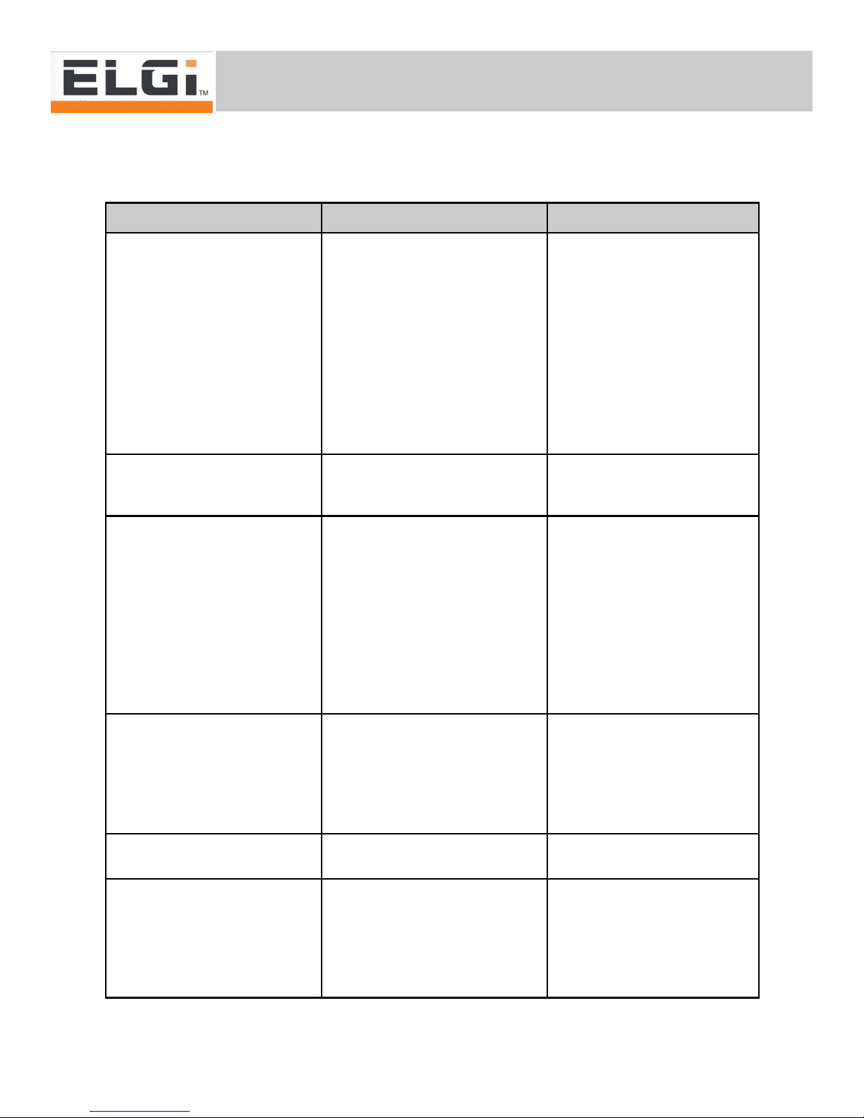
6.0 Troubleshooting
Problem Possible Causes Solution
Compressor over heats Dirty oil Change oil
Oil level low Fill correct grade of oil up to
max
level in the oil level indicator
Cylinder and cooler fins dirty Blow with compressed air or
clean manually
Breather valve not working clean and refit after checking
Rotation not correct Interchange two of the incoming
power feeds to motor
Compressor does not unload Blocked unloader tubing. Open and Clean
Defective unloader Replace pressure switch
Oil carry over in compressed air Dirty air filter Replace the air filter element
Oil level high Drain to correct level
Oil viscosity too low Change to recommended grade
Breather not working Clean and replace after check-
ing
Piston rings stuck or broken Change rings as a set
Piston to cylinder clearance ex-
cessive
Check and change as required.
Cylinder, piston and ring wear Inadequate filter maintenance Increase frequency of cleaning/
changing
Oil change frequency insufficient Increase frequency with more
periodic check of oil
Incorrect grade of oil Change to correct grade
Water or rust formation in crank-
case.
Faulty breather valve Check and replace the breather
Oil leak through breather valve Piston rings stuck or broken Change rings as a set, Check
all related parts for wear
Breather valve is not working. Clean and replace after check-
ing
Piston to cylinder clearance excessive Check and change as required.

15
TS Series
6.0 Troubleshooting (continued)
Problem Possible Causes Solution
Compressor knocking Loose compressor fan pulley Remove fan pulley and exam-
ine keyway and key for wear.
Change the key/pulley as re-
quired.
Worn out piston, cylinder, crank-
shaft and connecting rod bear-
ings.
Overhaul compressor unit. Re-
place the related components
Check valve faulty Replace check valve
Pressure built up time excessive Leaks in pressure lines. Repair leaks
Loose belts. Tighten or replace as required
Defective seating of inlet and ex-
haust valve plates
Clean and refit after careful
inspection
Worn out piston rings. Replace and check related
components
Unloader valve leaky. Dirty or faulty pressure switch Replace as needed
Pressure switch does not work Punctured diaphragm because of
frequent operations
Replace switch
Compressor package vibration Floor not level Check for level and correct
Foundation bolts and nuts loose. Tighten bolts and nuts.
Starter chattering. Loose connection in starter mains/
coil terminals
Tighten all the wires in starter.
Pressure switch malfunctioning. Replace pressure switch
Low supply voltage. Check supply voltage and cor-
rect
Contactor tip welding Foreign particles prevent contact
from closing
Replace contactor
Low supply voltage. Check voltage and correct
Short circuit. Trace and correct fault
Defective starter Replace starter
Starter tripping. Over load setting wrong Check motor FLA and set to
proper setting
Over loading. Pressure setting too high, ad-
just
Motor winding short. Replace motor

16
TS Series
6.0 Troubleshooting (continued)
Problem Possible Causes Solution
Starter tripping. Single phasing. Check all the three phases are
available at over load terminals
and at line side of starter
High Ambient Temperature. Provide proper ventilation. En-
sure ambient temperature is
less than 105⁰F
Overload Faulty Check amp draw of motor. If
overload is tripping below set
point replace overload
Voltage fluctuation. Control the fluctuation or stop
the compressor if the voltage is
too low
Frequent start stop Check the starts and stops per
hour. Should be less than 10
times per hour. If not increase
receiver volume.
Motor does not run in normal con-
dition
Faulty pressure switch Replace pressure switch
Faulty starter coil Replace starter
Single Phasing (humming noise
and motor does not produce
enough torque)
Check to see if all phases are
available at all terminals
Loose connection on starter termi-
nals, coil terminals or pressure
switch terminals
Correct the loose connections.
Motor overload tripping Check the reasons for tripping
and correct, reset by pressing
reset button on starter
Motor winding burnt Replace motor
Motor Faulty High ambient temperature Provide proper ventilation. En-
sure ambient temperature is
less than 105⁰F
Motor fan not rotating Check for defective motor fan
Over loading Check O/L setting and pressure
switch setting

17
TS Series
6.0 Troubleshooting (continued)
Problem Possible Causes Solution
Motor Faulty Frequent start stop. Check the starts and stops per
hour. Should be less than 10
times per hour. If not increase
receiver volume.
Defective winding Replace motor

18
TS Series
7.0 Replacement Parts - TS05
Description Part Number
Compressor 5 HP (X021151) 01-01-500
Compressor 5 HP (X020758E) 01-01-502
Filter Element (Metal Canister) 022400929
Filter Element (Plastic Canister) B005705760002
Drive Belt 11-01-114
Discharge Safety Valve 16-06-044
Tank Safety Valve 13-06-022
Check Valve 13-02-025
Pressure Switch 30-06-039
Pressure Gauge 23-01-003
Motor 208/230/460/3/60 03-04-006
Motor 230/1/60 03-04-006-001
Filter Element
Motor
Drive Belt
Discharge
Safety
Valve
Compressor
Pressure
Switch
Pressure
Gauge
Check
Valve
Tank
Safety
Valve
19
TS Series
7.1 Replacement Pump Parts - TS05
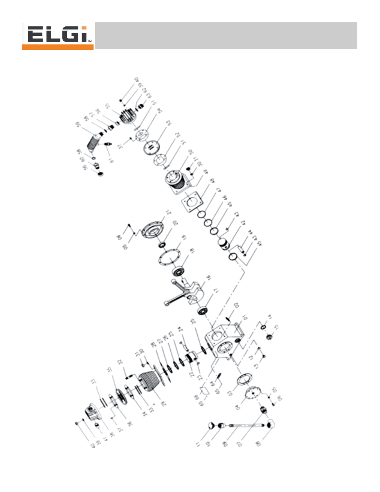
20
TS Series
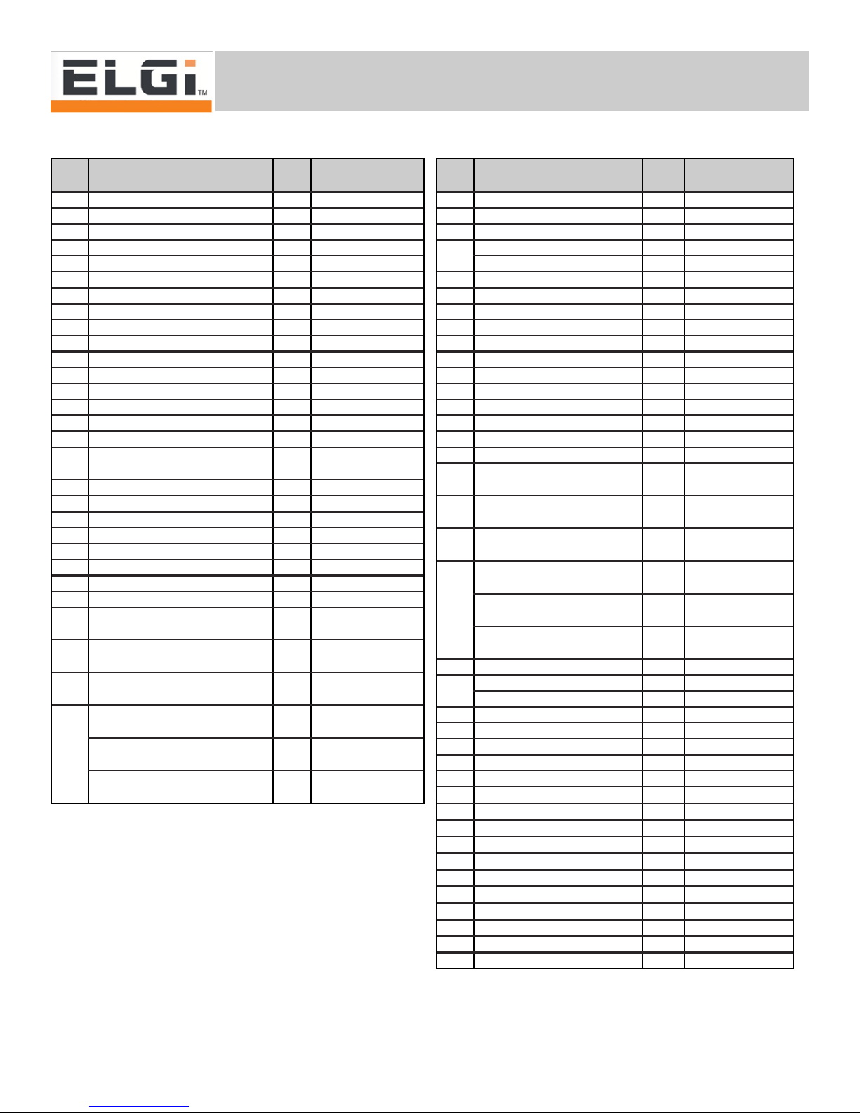
7.1 Replacement Pump Parts - TS05
Fig
#Description Qty Part No.
1Crank case 100 02 2560 0
2Stud M12 x 45 400 05 1456 0
Stud M12 x 54 400 05 1455 0
3Gasket, Free end cover 100 04 2550 0
4Free end cover 100 03 1770 0
5Spring washer M8 10 00 09 96 108
6Bolt Hex. M8x25 10 00 09 06 116
7Nipple hex. ½” BSP x ½” BSP 100 04 1843 A
8Elbow ½” BSP 100 09 72 053
9Pipe, breather 102 04 9285 0
10 Reducer ½” BSP x 1” BSP 102 04 9246 0
11 Breather assembly 1A02 0201
12 Rink packing, 17x22x2 100 05 2186 0
13 Oil Drain plug, 3/8” BSP 1A02 0033
14 ‘O’ Ring, OLI 100 05 2655 0
15 Oil Level Indicator 100 05 1344 0
16 Conn. rod & Combined Crank
shaft assy. 1A02 0231
17 Bearing 6305 100 09 03 346
18 Bearing 6307 100 09 03 352
19 Gasket, Fly end cover 100 04 2551 0
20 Oil seal, B32x54x7 100 04 2034 0
21 Fly end cover 102 03 5039 0
22 Piston, dia 90 100 32 0318 0
23 Circlip, B 18 200 09 17 218
24 Gudgeon pin, Dia 18 100 34 0757 0
25 Ring, slotted oil control, Dia
90 200 33 0478 0
26 Ring, stepped compression,
Dia 90 100 33 0477 0
27 Ring, Taper plain compres-
sion, Dia 90 100 33 0476 0
Gasket, C/Case to Cylinder,
0.75 100 04 1002 A
28 Gasket, C/Case to Cylinder,
0.4 100 04 1002 B
Gasket, C/Case to Cylinder,
0.25 100 04 1002 C
Fig
#
Description Qty Part No.
29 Cylinder, dia 90 102 03 5012 0
30 Spring washer M12 800 09 96 112
31 Nut, Hex. M12 800 09 48 012
Stud, M12 x 86 300 04 7004 0
32 Stud, M12 x 96 100 05 1450 0
33 Valve finger 400 03 3097 0
34 Gasket, Cyl. To Valve flat 106 04 0013 A
35 Valve Flat 100 33 0479 0
36 Gasket, Valve flat to Head 106 04 0012 A
37 Centring Bush 400 04 2660 0
38 Head, dia 90 Cyl. 102 03 6001 0
39 Spring washer M12 800 09 96 112
40 Nut, Hex. M12 800 09 48 012
41 Nipple, Pipe 1 ¼” BSP 100 04 3217A
42 Piston dia 50 100 02 1357 0
43 Circlip B 12 200 09 17 212
44 Gudgeon pin, Dia 12 100 05 1431 0
45 Ring, slotted oil control,
Dia 50 200 04 1683 A
46 Ring, stepped compres-
sion, Dia 50 100 04 1590 A
47 Ring, Taper plain com-
pression, Dia 50 100 04 1589 A
48
Gasket, C/Case to Cylin-
der, 0.25 100 04 1004 A
Gasket, C/Case to Cylin-
der, 0.4 100 04 1004 B
Gasket, C/Case to Cylin-
der, 0.75 100 04 1004 C
49 Cylinder, dia 50 100 02 1004 0
50 Stud, M12 x 60 300 05 2013 0
Stud, M12 x 70 100 05 1883 0
51 Valve finger 200 03 3094 0
52 Gasket, Cyl. To Valve flat 100 04 1150 A
53 Valve Flat 100 03 1005 0
54 Gasket, Valve flat to Head 100 04 1151 A
55 Head, dia 50 Cyl. 100 02 1993 0
56 Nut, Connecting 200 05 1038 A
57 Connecting Piece, ¾” BSP 102 04 8483 0
58 Ring, Packing 200 05 2191 0
59 Inter cooler 100 33 0525 0
60 Connecting Piece, 1” BSP 100 04 1204 A
61 Safety valve assembly, 100 04 1318 0
62 Ring Packing 100 05 2184 0
63 Adapter, ¾” x 1” BSP 100 04 1017 B
64 Direction Indicator 100 05 1010 0
65 Rivet 600 04 6454 A
66 Name plate, RAC Unit 102 03 5180 F
This manual suits for next models
2
Table of contents
Other ELGi Air Compressor manuals


Popular Air Compressor manuals by other brands


Stealth
Stealth SAUQ-1105 Operator's manual

BUSCH
BUSCH Mink MI 1502 Installation and operating instructions

Husky
Husky C201H Use and care guide

GEA Bock
GEA Bock HG22e Series Assembly instructions

Campbell Hausfeld
Campbell Hausfeld FP260000 Operating instructions and parts manual

Campbell Hausfeld
Campbell Hausfeld Cast Iron Series operating instructions