2.5
General functional description
1910.134 or F.D.A. 21 C.F.R. 178.3570 regulations.
Failure to do so may cause severe injury or death.
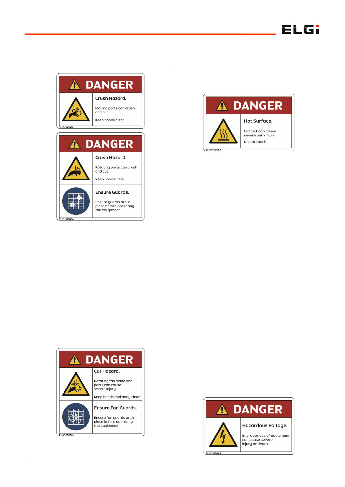
Insulate or use protective guards to cover pipes or other
parts that may exceed 80ºC (176ºF). High-temperature
pipes must have a clear marking as potentially
dangerous.
Position the compressor on level surface. In case of
inclined surface, contact ELGi.
Do not allow compressed air to come in contact with
food and related items unless they are compressed air-
treated specifically.
Be aware that this air compressor is intended for
generating only industrial-use compressed air.
2.3.2 Precautions during operations
When switching on remotely controlled compressors
ensure that no one is checking or working on the
compressor at that time.
Before starting, ensure that no tools or any loose parts
remain inside the compressor.
Do not operate the compressor if a possibility exists
that it could inhale flammable or toxic fumes, vapors or
particles.
Do not operate the compressor below or above its
operating limits.
Wear ear protectors if you work in an environment
where the sound pressure level reaches or exceeds 90
dB (A).
Keep all the compressor doors shut during operation.
For carrying out routine checks, the doors should open
only for short durations not more than 10 minutes.
Wear ear protectors when opening a door.
Keep hands, feet, floors, controls and walking surfaces
clean and free of water or other liquid to minimize the
possibility of slips and falls.
Pressure release
Know that annual servicing of the safety valve is
necessary. It should be checked at the prescribed
pressure for operation.
Use correct tools for maintenance and repair work.
Do not allow the manufacturers’ rated safe operating
pressure to exceed for pipes, valves, filters and other
fittings.
It is hazardous to point the compressed air directly
towards any personnel. Keep personnel out of the line
of the discharge air when opening hoses or other points
of compressed air discharge.
Use only the correct type and size of hose end fittings
and connections. When blowing through a hose or
airline ensure that the open end stays securely. A free
end will whip and may cause injury. Make sure to
depressurize a hose fully before disconnecting it.
Release all the pressure in the compressor system
before servicing or performing any maintenance
activity.
Do not engage in horseplay with air hoses. Serious
injury or death may result.
Do not use air at a pressure greater than 2.5 bar.g (36
psi.g) for cleaning purpose.
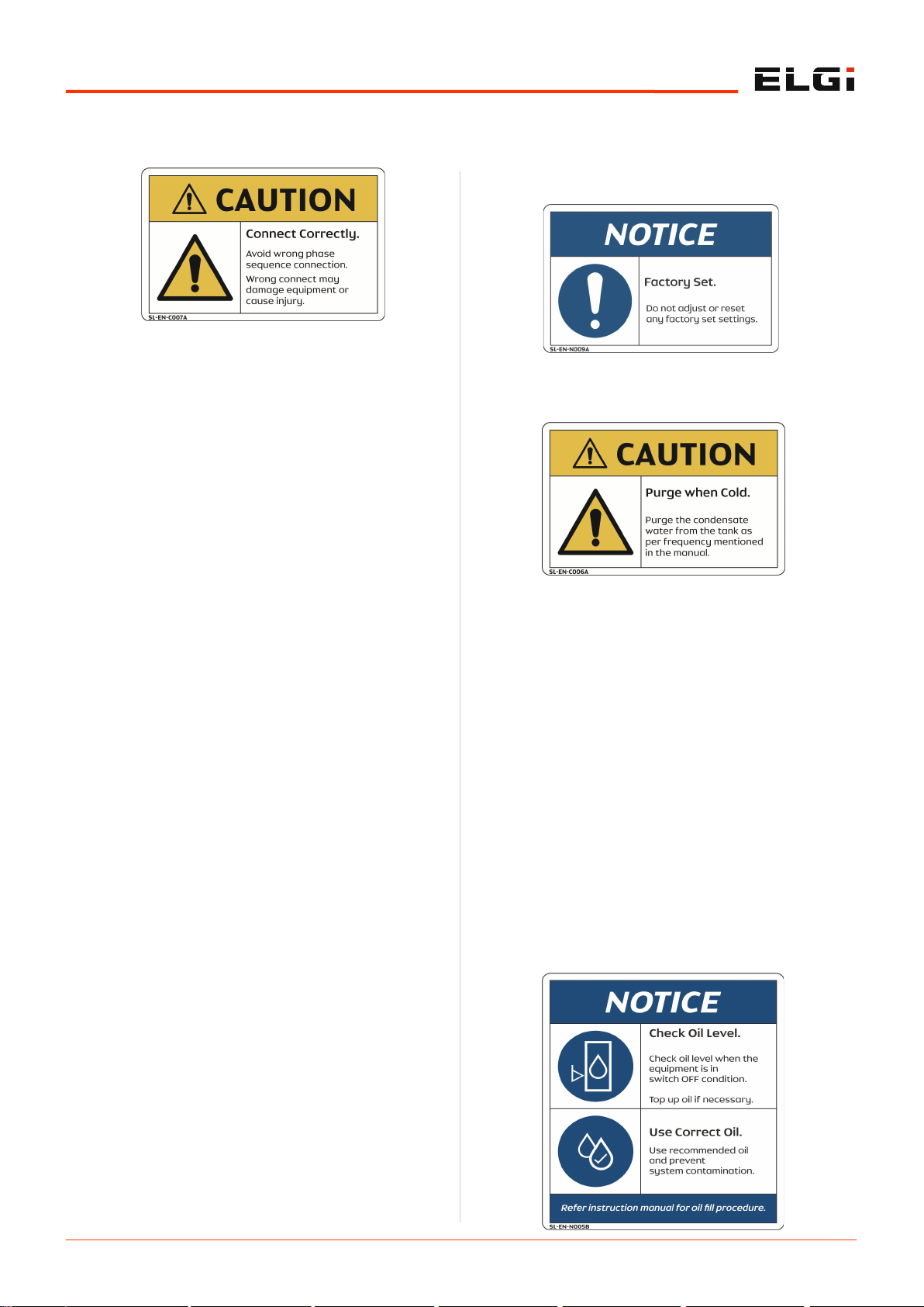
Open the oil fill cap only when the compressor is not
running and is not pressurized. Shut down the
compressor and bleed the receiver tank to zero internal
pressure before removing the cap.
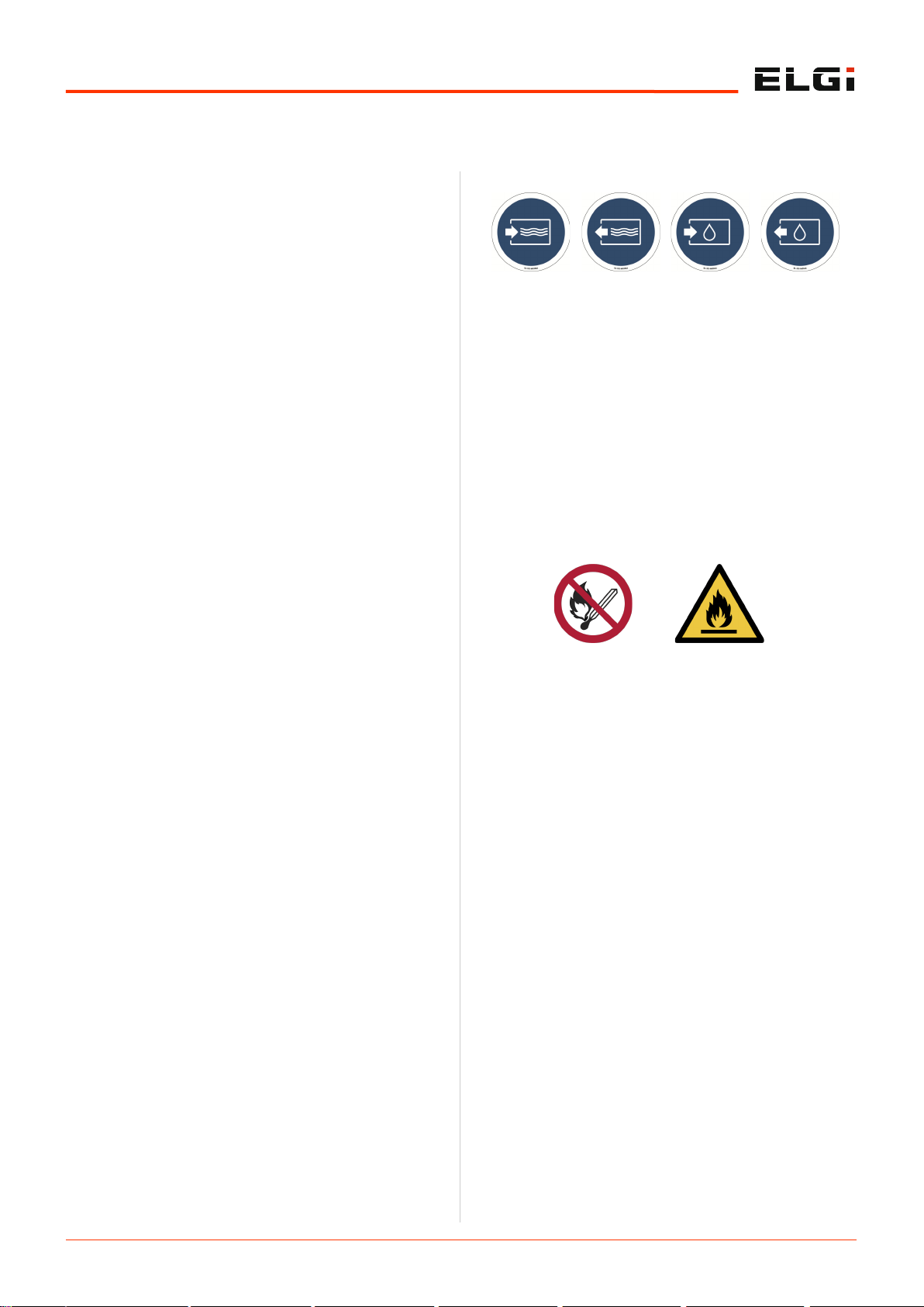
Fire and explosion
Clean up spills of lubricants or other combustible
substances immediately.
Shut down the compressor and allow it to cool down
before checking or adding oil. Remove sparks, flames
and other sources of ignition away from the
compressor.
Do not permit smoking in the vicinity of the compressor.
Do not use flammable solvents for cleaning purposes.
Keep electrical wiring and other terminals in good
condition. Replace any wiring that has cracked, cut,
abraded or otherwise degraded insulation. Keep all
terminals clean and tight.
Keep grounded conductive objects such as tools away
from exposed live electrical parts like terminals to avoid
arcing, which might serve as a source.
Keep oily rags, trash, dry leaves, litter or other
combustibles out of and away from the compressor.
Do not operate the compressor without a proper flow of
cooling air or with an inadequate flow of lubricant or
with a degraded lubricant.
Do not attempt to operate the compressor in a
hazardous environment of any classification unless the
compressor has been specially designed and
manufactured for explosive applications.