Elka ER 33 User manual
ER
33
DIGITAL
PROGRAMMABLE
RACK
SYNTHESIZER
MODULE
OPERATING
MANUAL

1
s=;y
a·•e
-.w;~-
__
_..
...
..
~--~~
....,_
.uY
-
-:
..
.
....
_
ELKA
would
liketo
thank
youf
or
choosing the
ER
33.
Th
is
instru·
ment
has
been
designed
to
produce
sounds
of
the
highestquali-
ty
and to guarantee a very hi
gh
standard
of
reliability.
In
order
to
obtai
n
the
max
i
mum
perl
ormance
fro
m
th
is instru-
ment
,
we
adviseyouto
fo
llow
th
e
ins
truct
ion
s in
thi
s manualwith
extremeattention.
~
--······-------·
--
-·~
•
•
jl:i:l
'-
·~
..
-
...
.
..
•
•
:
ELI<RP
m'E
SSlONRL.
~
.
noc
!B
en
,.,
CNIII_...
-· -
....
J
...
-..:"''QQa
-I I
:a aa
"ICI.
..,..,
.,.Tall
SPECIFICATIONS
The
ELKA ER
33
RACK is a digital programmable synthesizer
module
with
dynamic t
ouch
sensitivity functions and SECOND
TOUCH
(pressure controQ.
The
secret
of
the ER
33
isbased on
the
use
of
a digitally
control
-
led
generato
r (DCG). capable
of
generating nine voices.
ThedigitalgeneratorDCG Is
made
up
of
two
completely
separa-
te
·
Sounds
· , In Ofder
to
be
able
to
EDIT
or
Programme the
wund
Intosmall
blocks
.
me
ER 33
has
96
Presets,
of
wh
i
ch
32
are
programmable
.
The
memories
conta
ined in
the
RAM
33
Of
ROM
3311
cartridges,
expand
the
internal
memory
of
the
instrument
by
32
Presets.
A
32
character display, guides the
use
of
the various functions,
di
splaying all
the
parameters
wit
h therelative information(HELP
funct
ion)
thereby
ma
king
the
use
of
t
he
instrument very
much
easier.
Of extreme importance
in
live playing are the PERFORMANCE
REGISTRATIONS which,
by
means
of
the
16
butt
ons,
allow
the
memorizin
g,
as
we
ll
as
the
PRESETS,
of
all the playing facilities
(WHEEL.
MU
LTISPLrT, MIDI. etc.).
Thanks
to
MULTISPlrT,It
is possibleto divide
the
keyboard
into
eight
sections,
each
with
it'
s
own
different
timbre
and
MIDI
channel.
This
permitsthe connection
of
the
ER33
to
a mutti·tract<
sequencer, thereby obtaining surprisingly
real
ist~
orchestral
effects
.
ER33
PRECAUTIONS
To avoid damage
and
defective working,
do
not
use
Of
lea~e
the
instrument.fOf long periods, In dir
ect
sunlig~
.
in
~xtreme
htgh
Of
low
temperature
Of
hum
idity conditions,
oc
1n
dUsty and sandy
areas.
'des
the
Be
sure
to
check
that
your
AC
power
supply
outlet
provt
correctvotta
ge
fOf
the
instrument. .
The
instrumentissupplied
with
aninternal
Uthium
battef)',
whtch
keeps
the internal
mem
ory,
used
fOf memorizingthe
ti!l'bres
and
PerfonnanceRegistrations, in activity. also
when
the
tnstrument
is
turned
off.
The
life
of
this batterygreatly
depends
on
the
~
bient
concfrtions; howevertheinstrument's internal
computer
Will
give
wam
i
ng
on
the display,
with
the~~
·e.rrOf Replace
Battery• whena newone is necessary.
tt
IS adVIsable
to
havethe
batteryreplaced
by
a qualified technician.
To
clean
the
outside surfaces
of
the instrument, use
only
a
soft
dry
doth.
Nev
er
use
petrol, alcohol
or
other
solvents,
as
these
will cause damage
to
the surface finishes
and
panel.
CONNECTIONS
·-
0
HEADPHONES
0 •• •
I M
_
__..,
__
....
.
MIX
ER
0
2
AMPLI
FIER
For
MIDI
connections see
below.
Tc
A.
C.
.
L.
............................
--
...................................
f<1~~T
so~k
•
(
8-
600
ohms}
VP-10
PED
AL
M
P-7
PEDAL
MP-7
PEDAL
MP-7
PEDAL
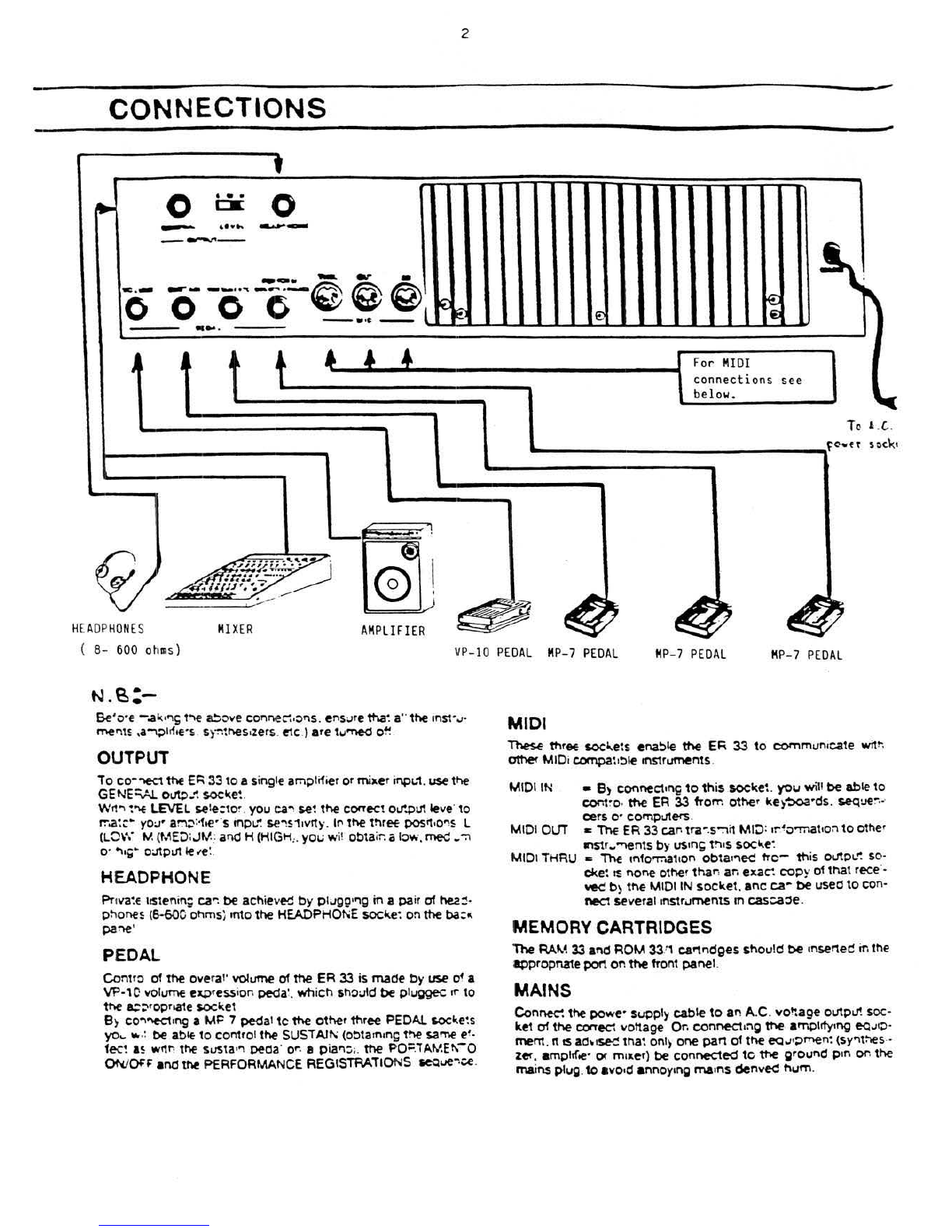
N.~:-
ee·,,-e
-,al(
o'1
~
1'"\E a!;ove COI"If"lei:":•Of"IS.
ens:.Jre
tt\a~
a•
·
the
ln$1'..1·
tnef"ll~
,a"""l;)h1•e·s
sy~~"E!s
o
zers
.
e-tc
) are tu-ned
o~
.
OUTPUT
To
co-"'EC1 thE
Ec:\
33
to
a si
ng
le amplifier or miller
ir\pL.1
.
use
tl'\e
GENE
:::.Al.
o~_-t
$0CI(e~
.
W11
"'
~"*
LEVEL
se
t
e:t
o~
.
you
ea~
se
~
the
COI'Tect
o..r.pU11eve
·
to
r.-.a~c
..
yo:.J•
ar.'l;':·f·e··s inpLt.
se~s'1
1
vrty.
lr
the
t!'lret
posit
o
O'lS
L
(LOW
M (ME:J:
JM
.:
al'\d
H (HIGH
,.
ye~,;
wi
!
obtair.
o lov.·.
med
~
~
o·
~.,
..
o~piJt
le
.-e
:.
HEADPHONE
Pnva~E
hsteni
n;
ea--:
be
achieved
by
ptugQ'
"9
in
a
pa
ir of
he2:-
phones (6-600 ol1ms) rrrto
the
HEADPHOt-.iE
socile~
on
the
ba
: ..
pa~
·
PEDAL
Cont
ro of
the
overal'
volume
of
the
ER
33
is
made
by
use
of
a
VP-10
volume
u.
pr
es.s
ion
peda
~.
wh
i
ch
sh
ould
be
piu~
If'
to
the
a:-::-
•opr.ate
socl(et
B)
CO"~"K1
•n
g
a
MP
7
pedal
tc
the
other
three PEDAL
socl(e~s
yo
..
"'
.:
be
ab~
to
comro
l
the
SUST
Alfli
(Otltaonong
the
$2"Tle
e!.
fee!
as
wf1
t;
the
susta
•" peda'
O"
· a pia.,:;;.
the
PO=
.
IAME~-o
e>won·
and
the
PERFORMANCE
REG
IS
TRATIONS
seQue~.:e
.
MIDI
These
three
socl...ets
ena~le
the
EF;
33
to
COI'Tirnun
icate
witr
.
other
MIDi
compa~
o
:>le
rnstruments.
MIDI IN
MID
I
OLTT
MID
I
THRU
•
B)
connecM~
to
this
.
soc~e~
.
you
will
be
able
to
cor.t~O·
the
ER 33 fTorr. other ke)-:>oa•ds.
seque:-
.~
cers o· cornpiJters.
c The
ER
33
car·
tra~
.
s~i1
MI:J:
.r•o-mat•on
to
other
ln$1f
w~ntS
by
US
In~
t!'IIS
$OCI<.e~
..
The
mforr..at.on
obta
•
'"leC
trc-
th
is outol..": so·
cl(e~
I!
none
other
thar
:
ar
.
exa~
copy
of
that
rece·-
vec
b)
the
MIDI IN
soc~et.
anc
c;a~
be
useo
to
con-
nect
severa
l•nstruments
m casca::se.
MEMORY CARTRIDGES
The
RAM
33
and
ROM
33
.'
1 caf"!f"ldges
should
be
•nserted ir.
the
appropnatepen
on
the
front
pane
l.
MAINS
Con~
the
powe· supply
cable
to
an
A.C .
vo!tage
outpLJ! soc-
ket
of
the
COtTe-cl
vottage Or. connect•:'IQ
the
arr.pltfy•ng
eQ
..
HO·
ment
.I'IIS
ad~•see
tha~
onl) one
part
of
the
eQ..J•pmen~
(sy.,t:;es.-
zer. ampltf.e·
01'
m•
a.er)
be
connected
tc
the
groul'\d p•n or.
the
ma
ins plug.
to
avo•d annoy•ng
ma
on
s
denv~
hum
.
3
M\\:)\
CoNNE.C\
\o\JS>
The MIDI (Musical Instrument Interface)
is
a digital Interface
which allows different
types
of
musical instruments
(M
IDI com-
patible)
to
communicate with each other.
In
ttle
case
ofthe ER
33,
thisinterface permits the transmission
of
the data
of
all
the
outstanding features
of
this
synthesizer
mo-
du
le
to
otherInstruments andusingthe same techniquescan r
e-
ceive all the neces.sary MIDI information needed
to
controlthese
same functions from any other M
IDI
compatible instrument.
MIDI IN M
IDI
OUT and MIDI THRU are the three sockets
by
means
~f
which
the
ER
33
can
be
connected
to
a keyboard,
se-
quencer, synthesizer
etc
., as explained in
t
~
CONNECTIONS
section, F
or
some examples ofvanous M
IDI
connec-
tions,you should consult Fig. 1 MI
DI
CONNECTION EXAMP
LES
(below).
The
ER
33
canreceive
ttle
following information on theMIDI
bu
s
(MIDI IN):
1. KEYBOARD
OAT
A (Key On I Key Off).
2.
KEY
VELOCITY SENSITMTY (Keyboard Dynamics)
3. SECOND TOUCH (Pressure used on the
keys
after the note
has been played.
~
.
PROGRAM CHANGE (changing
of
thePRESET number).
5. MODULATION CONTROL
('WHEEL
, MODULATION,
SE
-
COND TOUCH).
6. PEDAL EFFECTS (Volume Pedal, Sustain Pedal, Portamento
Peda
l).
7. SYSTEM EXCLUSIVE
f)
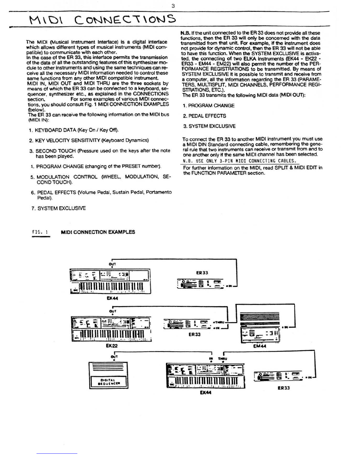
s. 1 MIDI CONNECTION EXAMPLES
-
..
-.
.
--
-
0\11
•
EK44
i'
ll.
EK
22
OUT
•
=
OIO
IT
AL
aaoua..c
l•
. -
I
N.B. H
the
unit connectedto
the
ER
33
does
not
provide allthese
fu
nctions, then the ER
33
will only be concerned with the data
transmitted from
that
unit. For example,
If
the
Instrument
does
not
provide for dynamiccontrol,then
the
ER
33
will n
ot
be
able
to
have this function. When
the
SYSTEM EXCLUSIVE
is
activa-
t
ed,
the
connecting
of
two
ElKA Instruments
(EK
44 - E
K22
-
ER33-
EM44-
EM22) will
also
permit
the
n
umber
of
the
PER-
FORMANCE REGISTRATIONS
to
be transmitted.
By
means
of
SYSTEM
EXC
LUSIVE
it
is
possible to transm
it
and receive from
a computer, all t
he
lnfoonation regarding the ER
33
(PARAME-
TERS. MULTISPUT, MI
DI
CHANNELS. PERFORMANCE
REGI
-
STRATIONS,
ET
C.).
The ER
33
transmits
the
following M
IDI
data (MIDI OUT):
1.
PROGRAM
CHANGE
2. PEDAL
EF
FE
CTS
3. SYSTEM EXCLUSIVE
To connect
the
ER
33
to
another MIDI instrument you must use
a MIDI DIN Standard connecting cable, remembering the gene-
ral rule
that
two
instruments canreceive
or
transmitfrom and
to
one
another only
if
the
same
MIDI channel
has
been selected.
N.B.
USE
ONLY3-
PIN
MI
OI
CO
NN
ECTI
NG CA
BL
ES.
For further information on
the
MIDI, read SPLIT &MIDI EDIT in
the FUNC
TI
ON
PARAMEI
ER
section.
ER33
ER33
.C' £
;:
c.·
r_
..
,..,
•
U44
----
---
-·
~
--
--·
....
~
--
..
.
~
.-5
..c:::
: ll!i
EM44
,.
~
·-..-.. .
....
--
ER33

PRESET SELECTION
Before
switching
the
instrument
on
.
ensure
that
all
the
connec-
tions
have
been
carr
i
ed
ou1
correctly
. If
so.
then
sw
i
tch
on
the
in-
strument
by
tum
1
ng
the
MASTER
VOLUME
control
in
a
dock-
wi
se
direction
.
At
this
po
i
nt.
after
a fev.
seconds.
the
display
will
show
the
following
information:
A-(:~~~~~
DCG
PRESET NAME \
:i~~-
)-c
'
B
•
A -
Ind
icates
the
PRESET
number
.
The
pref
1x I
or
C
shows
whether the PRESET
is
internal
or
f
rom
the
CARTRIDGE.
B ·
Name
of
PRESET. .
C
·Number
of
the
PERFORMANCE
REGISTRATION
1n
opera-
ti
on
(the
pref
ix I
or
C
ind
i
cates
whether
the
case
of
an
inter-
nail~
recorded
PERFORMANCE
REGISTRATION
or
that
of
one
from
th
e CARTRIDGE).
lnsta
n: select1on
of
one
of
the
96
PRESEiS
al
reaoy
program-
med
. IS
010w
avatl
able
by
means
of
the
numenc
~eyboard.
PRE
:-
SET
SELECTOR.
MULTISPLIT
By
presSif\Q
the
M
UL
TISPLrT
butt
or
you
activate
the
MULTI
-
SPUT
function.
MUL
TISPUT
allows
a
further
divisi
on
of
th
e
keyboard,
up
to
a
max
i
mum
of
ei
ght
di
st
i
nct
i
ve
sect
i
ons
.
with
ei
ght
PRESETS
and
e1gt1t
different
MIDI
channels.
By
means
of
the
two
SCROLL
I
and
SCROLL
1
bllttoos
you
car
. read all
the
i
ndicat
i
ons
concem
1
n;
the
ei
ght
SPLITS
on
the
d1
sp
1ay. that is.
the
number
of
SPLITS
.
the
PRESET
(whictl
can
be
modified
by
the
method
a
lready
des
cribed).
the
separation
po1nt (SPUT
POINT)
and
lastly
.
the
LOCAL
OFF
control,
whictl
indicates
wt11ch
SPLIT
number
is
not
in
operation
on
the
key
·
boa
rd.
Th
1s
contro
l
only
woi'Xs
on
the
keyboard
versi
on
of
the
33
mode
l.
The
vo
lume of
each
SPLIT
is
controlled
by
the
MUL
TISPUT
VO
·
LUME
potent
i
ometer
.
The
volume
acts
on
the
PRESET
shown
on
the
di
sp
l
ay
.
4
Then
form
the
number.
having
first
controlled
the
numeric
refe-
rence
table
of
the PRESETS srtuated
on
the
top
pane
L
The
display
wi
ll
begin
to
flash
and
will
stop
only
once
you
have
pressed
the
ENTER
button
.
The
name
of
each
new
PRESET
will
appear
on
the
display
and
it
is
immediately
ready
to
be
played
.
The
overall
volume
is
controlled
by
the
MASTER
VOLUME
con-
trol.
The
volume of
each
PRESET
(also
in
the
MUL
TISPLIT
mode)
is
controlled
bY
the
MUL
TISPLIT
VOLUME
potentiometer
.
By
inserting the CARTRIDGE.
you
will
have
the
possib
ili
ty
of
ex-
pand
ing
the
capacity
of
the ER
33
's
memory
by
another
32
PRE-
SETS
and
16
new
'PERFORMANCE
REGISTRATION
S.
these
then
be1ng an alternative
choice
to
the
32
PRESETS
and
16
PERFORMANCE REGISTRATIONS
wh
ich
can
saved
in
th
e
in-
struments
imema
:
memory
system
.
To
se
l
ect
any
o
ne
of
the
PRESETS
or
PERFORMAN
CE
REGISTRATlONS
from
the
CART-
RIDGE,first
pre
ss the
CARTRIDGE
button
m
the
PRESET
BANK
section
. then f
orm
the
number
of
the
PRESET
required
(from
65
to
96only)
or
press
one
of
the
16
PERFORMANCE
REGI
STRA-
TlONS
.
If
you
se
l
ect
a PRESET
or
PERFORMANCE
REGISTRA-
TI
ON
from
the CARTRIDGE.
wnen
in
fact
the
abovement
1
oned
cartridge
has
not
been inserted in
to
the
rear
port.
then
the
mes-
sage
·erro
r·
will
appe
ar
on
the d1splay.
To
pass
from
a CARTRIDGE PRESET
to
an
11\'TERNAL PRESET.
just
press
the
blltton
marked
INTERNAL
m tl'le PRESET
BANK
sect
ion.
The
eight
SPLITS
have
a
poss
ible
maxim
um
of
nine
polyphonic
voices
.
with
dynamic
ass
ignment
along
the
~eyboard
.
Theref
or
e.
if
you
ctloose
to
play
one
of
the e1
ght
with
,
let's
say.
four
notes.
you
can
play
the rema1mng
f1ve
notes.
in
one
or
more
of
the
other
SPLITS. (See
F1g
. 3
in
SPLIT
POINTS
in
the
SPLIT
&
MIDI
EDIT
sect
i
on
of
the
FUNCTION
PARAME
I
ERS
.
Remember
that
to
obta
in
the
M
UL
TISPUT
effect.
you
must
have
a
keyboard.
sequencer
or
other
mstrument
tr.at
has
the
poss
ib
il
i-
ty
to
transmit
on
several
channels
.
or
else y
ou
will
have
to
set
the
ER 33 in
the
OM
NI
ON
mode
.
Only
in
th
is
wa
y
will
you
be
able
to
have
the
M
UL
TISPUT
effect
or-
your
keyboard
.
For
the
setting
up
of
the
OMNI
-
ON
and
OFF
mode
and
f
or
MUL
TISPLIT,
you
should
read
-sPLIT
AN
D
MID
I
EDir
in
the
FUNCTION
PARAMETERS sect1on.
PERFORMANCE REGISTRATION
Thanks
to
the
sophisticated
technology
employed
by
ElKA
in
the
des•gn
of
EK
44
,
it
is
possible
to
programme
and
memo0ze
.
by
means
of
the
16
buttons
of
tl'lE
PERFORMANCE
REGI
-
STRA
T
ION
section.
several
important
funct
i
ons
of
the
instru-
ment
and recall
them
even
during
a
particular
sequence
of
a
per-
formance.
In
this
way
.
you
can
change
the
rec
ordings
already
made
with
exact
tim
ing
and
withou1
any
loss
of
continuity
in
the
sequence
.
Wi
th
the
16
buttons
of
the
PERFORMANCE
REG
IS
TRATION
S,
the
memorizing
of
t
he
following
is
possible
:
a
·Presets
assigned
to
NORMAL
or
MUL
TISPUT
function.
b
-SPLIT
position
on
keyboard
.
c
·Volume
of
PRESETS
and
of
an
the
SPLITS
.
d
-All
the
values
chosen
in
the
FUNCTlON
parameters
1-2-3-4-
5-6-13-14-15-16-17-18-19-20·21.
by
follow1ng
the
procedu-
re
described
furth
er
ahead
in
the
•11struct1
ons
.
After
having
decided
the
TIMBRES
in po1nt a (above).
the
SPLITS
(b). the
VOLUMES
(c)
and
the
vanous
values
of
the
FUNCTlON
parameters
(d).
press
the
RE
CORD
button
at
the
end
of
the
l
ine
of
PERFORMANCE
REGISTRATI
ONS
bi.Jttons
together
with
one
of
the
16
buttons
whe!"ever
memoring
of
the
a-b
-e-d
situat
ion.
outlined
above
. is
reqwed
.
Take
irrto
account
that
the
PERFORMANCE
REGISTRA110N
wi
ll
be
saved
in
the
internal
memory
or
in
that
of
the
cartridge.
de-
pending
on
wtlich
of
the
two
buttons.INTRNL.
or
CARTR.
(PRE·
SETS BANK)
has
been
pressed
.
EDIT &
FUNCTION
By
us
i
ng
EDIT and FUNCTION.
access
to
all
the
p4'ogrammrng
parameters
of
the
instrument.
is avai
lable
.
Wtth
the
push
-
button
.
EDIT,
s.elec1ion
of
all
the
pa
r
ameter$
con
-
cemrng
the
prog
~
amming
of
a PRESET
becomes
possible
.
wnrce
press
•
no
the
FUNCT
.
butt
on
act
wates
those
contro
l parameters
of
the rnstru
ment
used
duri
ng a
performance
(periormance
para-
meters
).
To
vary
the
PRESET
or
periorman
ce
parameters
.
fo
ll
ow
the
pro-
cedu•e
below
:-
, -Press the EDIT or
FUNCT
.
bvnon
The
last
pa
rameter
num
-
be
r that
wa
s recalled wi
ll
al
wa
rs
be
shown
on
tr·.e di
sp
lay.
2
-Form
the number
of
the
pa
ra
meter
to
be
modifred
.
after
ha\
·
•ng
consulted
the
approp
rr
ate
tab
le.
ano
then
press
the
ENTER
button
.The
tab
le covenr:g
the
EDIT
parameters
is
on
the
top
parle' and refers
to
the
.,umbers
frof"''\
1-12
and
21-38
.
as
rs
the Perfonnance
paramete
r
tab
le (FUNCTION)
numbers
1-23
(
~note 1
be
lo
w).
'3-
The
;>arameter
rn
Question and e
t's
value will
no"'
·
be
shown
on
thE diSpla
y.
B)
means
of
the
VALUE
potent
:
ometer
and
tl"'e
-/On!Yn
and
-/Off/No
buttons tt rs
poss
i
~!e
to
modrf}
the
va
lues of
the
pa
rameters. Usrng
the
pote
nt
ro
me
ter f
or
the
Or
gger
varia-
tions whr
le
the
tw
o
bvnons
ca
r.
be
used
f
Of
untt
by
unit
va
ria-
trons.
4 -Once the
pa·a~eters
have
been
cc.,.ected.
to
leave
the
EDIT
or
FUNCTION
mode.
press
tl"'e
INTRNL
.
or
CARTR
.
button
.
FUNCTION PARAMETERS
5
Afte
r thiS
last
operatton.
both
the
pa
r
ameters
of
PRESET and
those
of
performance remain acti
ve
and
can
be
memorized:
the
first
by
means
ofthe
SAVE
procedure. while
the
second
by
using
the PERFORMANCE REGISTRATIONS.
On
leav
r
ng
the
EDIT
0t
FUNCTION
proced
ure a dot will
be
shown
to
the
right
of
the
PRESET
number
or
FUNCTION j
ust
edited
a
nd
to
that of
the
PERFORMANCE REGISTRATIONS.
thus
rndi
cat
r
ng
the
tempo-
rary
change
of
timbre
or PERFORMANCE REGISTRATION.
Both
the
PRESET and PERFORMANCE
parameters
.
if
not
me-
morized
will
be
cancelled
as
soon
as
another PRESET
or
PER-
FORMANCE
REGISTRATION is
se
lec1ed.
Of
if
the
instrumem rs
•
sw
it
chec
off.
One
of
tr-.e
most
i
mporta
nt features
of
the
ER 33 rs
the
KELP
funct
oon
. Us
rn
g
th
iS
button
. after havr
ng
ente
r
ec
rn
to the
pr
o-
gramm
r
ng
wrth EDIT
or
FUNCTION.
prov
r
des
some
very useful
informat
•
on on
an
the parameters.
thus
.
mak
r
ng
the
ae1ual
pr
o-
grar.-~f'l"'
.
ng
itseH
vef)·
much
easier.
In
fact
. all
the
information regardi
ng
the
chose"'
parameter. will
be
sl'low"'
on
the
d
rs
play
.
To
rme.,.upt tl'lrS
opera
tron.pu
sh
HELP,
a
sec
on
d
tim£
.
or
wa
rt
unt
rl
the
e
nd
of
the
phrase
.
The
display
will
no"'
show
the
se
lected
pa
rameter.
Note
n•
1 -
11
rs
also possible
to
move
from
one
parameter
to
an
other
. without forming the
number
.
by
I'IO
I
Ori'IQ
down
the
ENTER
key and
mo
vi
ng
. with
the
ot!'ler
nand
.
the
VA.LUE
cont
r
ol
to
-Of - . In
th
rs way a
ll
the
pa
r
ameters
w
rll
be
dr.splayed one
afte
r
the
other.
The
=
~ h :1
1
0
k
h~t
tor
,to
be
foun
C i r
~h
t
P~0GRA
•
t:CESS
se,tioft
o ~
the
front
pa~e
l
t o
the
left
of
th~
nu
ee
ric
P~[S~l
S[l[(lCK
kty
pad,allows
ch
a
~Q
~ S
t~
a
ll
th~
va
rious
Ptrf:r
aa
nc
e
fu~ctionsnot
directly
c
onc~rn~d
w
ith
th~
Ti abre
to
b~
•ad~
.
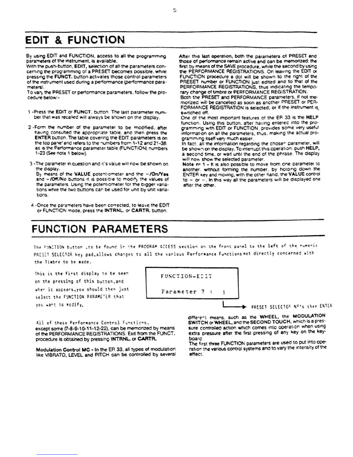
This
is
the
first
disp1ay
to
b~ see
~
on
t~e
pr~
ssi
ng
of
th
is
button,and
w
h~r
i t a
pptars
,y
ou
should
th~~
just
s
~l~
~t
t ht
f~
N~llON
PARA~t
'
[R
t
ha~
yo"
.
ar.~
tc
w c
~ify,
Fl'SCTI
O
N-E:
~"!'
ra:-al!le":er
? .
• 1
A
ll
of
these
P
erf
or•ance Contr
cl
f~~cti:ns
..
except
some (7-8-9-1G-11-
12-22
).
can
be
memorized
by
means
of
the
PERFORMANCE REGISTRATIONS.
Exit
from
the
FUNCT.
procedure is obtained
by
press
in
g INTRNL
or
CARTR.
Modulation
Control
MC
-In
the
ER
33
. a
ll
types
of
modulat
i
on
like VIBRATO, LEVEL
and
PIT
CH
can
be
controlled
by
severa
l
I'---~·~
PR£S
E1 SELEClO:
t;
t•s
the"
[1\H~
ditfe·
e-:
mear.s. s
uch
as
the
WHEEL
,
th€
MODULATION
SWITCH
or
WHEEL, and the
SECOND
TOUCH
.
wn
ich
is
apre
s·
sure
comrolled
act
r
on
wn
r
ch
comes
rnto
opera
t.on when
us
rn
g
extra
pressure after
the
first
press
i
ng
of
any
~ey
on
the
key-
bK)arc. .
ine
frrst ttYee FUNCTION parameters are
used
to
put
·~to
ope-
ratror
the
various
contro
l systems a
nd
to
vary
the
rntensrtyof the
effect.

6
1 •
VlBRATO
• 0 • 7
By
means
of
the
fii'St
three buttons
of
the
PERFORMANCE
REGISTRAnONS,
you
can
put
into operation
any
one
of
the
three
methods
of
modulation control.
With
button N. 1 you
can
activate
the
WHEEL. then nioYe
tt
to
obtain
the
effect
. . .
By
press
i
ng
button
N.
2.
the VIBRATO
effect
Is
obtainable
by
means
of
the
MOOULAnON
SWITCH
or
WHEEL
W
ith
button
N. 3,
the
VIBRATO
becomes
effective
with the
SECOND
TOUCH
on
the
keyboard.
You
can
vary
the
VIBRATO DEPTH
by
using
the
VALUE
control
or
the
+
or
-buttons, whilethe SPEED
will
depend
on
the
tim-
bre
chosen.
H.ln
the
PRESET
selected, Parameter34 (VIBRATO M.C. SENS.)
of
the
EDIT
section
is positioned at zero,
no
effect
wi
ll
be
obtained
.
The
VIBRATO function
can
be
activated
or
disactiva-
ted
at
anv
OOint
in
the
MUL
TISPUT
bv
mean
s
of
Par
ameter
16
(VIBRATO
ONtOFf)
.
To
act
ivate
th
is
effect
when
us
i
ng
a full
un-
split
keyboard, Parameter 16
must
be
in
the
-
oN
" position
for
SPLIT
N. 1.
CONTROL
METHOD
VISR.
MC.
SOURCE
lhis
:is
play
:s
sho~
ing
tha
t ycu have
thos
f-
the
~
~:El
•e
thod
of
Vl!~AlO
MO
O.
c
~ n t•
:
!
a
nd
:-
thi
s
ca ~e
tht
Q[Pl"
ha~
beer
~e
t
at
l
va
l~
e
of
5.
~l+-
~00
TCt-!
(
~
)
1
2 • LEVEL •
0-7
Th
is
p
arame
ter
allows
control
of
the
VOLUME
of
SOUND
1.
by
means
of
the
three
met
hod
s described
above
. Wrth
the
sam
e
first
three
buttons
of
the
PERFORMANCE
REGtSTRAnONS,
choose
one
of
these
methods
. while adjust
in
g
the
DEPTH
with
~
; I
·:
VALUE
CC
iHRC.L
or •
I-
B•J1
1
0hS
L.
---------~-~
~(R
f
CR
"L';([
;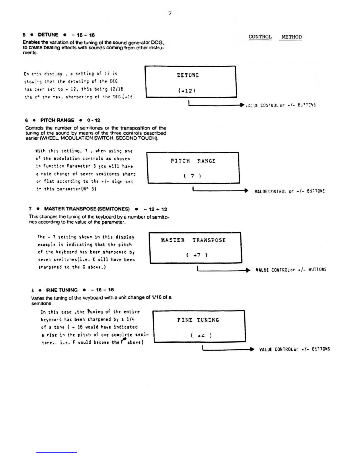
5 e OETUNE • -
16
+
16
Enables
the
variation
of
the
tuning
of
the
sound
generator
OCG.
to
create beating effects
with
sounds
coming
from
other
instru-
ments.
On
t ·
:
~
~is:~ay
• a
setting
of
12
is
$~~-
~
-~
tht:
tht
de:u
~i~~
of
t~t
DCG
t.ts
:efr
s
e~
to
•
12,
t~is
beirg
12/16
t~s
et
tl\
f
•at.
!1-a~per
:.rg of : he
~CG.(.lf
·
6 • PITCH
RANGE
• 0 -
12
Controls
the
number
of
semitones or
the
transposition
of
the
tuning
of
the
sound
by
means
of
the
three
controls
described
earlier (WHEEL. MODULATION SWITCH. SECOND
TOUCH
).
7
CO
NTROL
METH
OD
DE
TUN£
V
ith
this
setting,
7 ,
~her.
using
ont
ol
the
•
odulation
contr,ls
as
chose
n
:
~
Function
Paraeeter
3
you
~
ill
have
a nGtt
chan~e
of
seve
r
seeito
nes
sha
r=
or
fl at
a
~co rd
i~
g
to
tht
•I-
sign
set
in
this
~
a
r
aee
t
er
(
NG
3)
?lTCH
RANGE
7 •
MASTER
TRANSPOSE (SEMITONES) • -
12
+
12
Th
•s
changes the tuning
of
the
keyboard
by
a
number
of
semito··
nes
ac
co
rd
ing to
the
va
lue
of
the parameter.
( , )
'-'---------1·~
Vll'.J[
C!llili<QL
or •f-
so;:lQN~
lhe
• 7
set
ting
sho~n
in
this
disp!ay
t~ac
;!e
is
ind
ic
ating
that
the
Pitch
of
th
e
ke
ybotrd has beer
sharpen~d
by
seven
se•
i~~~
t
s
( i
.
e
.
C
~ill
have
bet~
'ha
rp
tned
to
tht
G
above.)
MA5!ER
T~ANS?
05
E
l •
F1NE
TUNING
• -
16
~
16
Varies
the
tuning
of
the
keyboard with a
un
it
change
of
1/16
of
a
semitone.
In
this
cast
,t
he
~
uning
of
tht
ent
ire
keybo
ar
d has been
sharpened
by a
1/4
of
a t one ( •
16
would
ha~e
ind
ic
ated
a
rise
in
the
p
itch
of
one
co•plete
seci-
tont.-
i.e.
f w
ould
btco•e
the
tt
abo
ve)
(
·'
)
'-1
-------·P
UL!JE
CONlROLor
•
/-
B!JllO
ICS
F!NE
Tt:NlNG
(
.~
)
I\.------~·,..
VAL!.IE
CO
NlROlor
•/-
B!J:lOitS

8 •
ARAB\AN
SCALE
•
Off-
Edit-
On
OFF
•
Chromatic
Scale
EOfT
• Arabian scale, which
becomes
available
on
exit
from
the
FUNC'TlON
mode.
in
plaoe
of
the
PERFORMANCE
REGISTRA·
110NS
.
ON
•
Allows
you
to
memorize
the
last
chosen
Arabian
scale
and
gives
Immediateuse
of
the
PERFORMANCE REGISTRA110NS.
By
means
of
the
sophisticated
technology
used
in
this
instru-
ment,
the
tuning
of
each
of
the
twelve
notes
in
the
musical
scale
Is
possible
, thereby permitting
the
fanning
of
every
kind
of
tva-
bian
scale.
lhe
procedure
to
use.
is
as follows:
1 - Press FUNCT10N
and
select
parameter
N. 9
2-
Now bring VALUE
to
the EDIT
position
by
means
of
the+
button.
8
3 - Leave
the
Function
mode
using
the
INTRNL
or
CARTR
.
button
.
At
this
point
the
first twelve
numbers
of
the
PER-
FORMANCE
REGISTRAT10NS
WOf1( as selectors
to
switch
the
twelve
normal
sem
i
-tones
to
semi-tones
used
for
Arabia
n
music
.
4-
I
ex*
at
F.g. 2
and
you
will
see
that
each
of
the
first
twelve
numbefti
COrTespoods
to
a
given
note
. Referring
to
th
is
dia
-
gram
just
press
one
or
more
of
the
first
twelve
numbers
and
you
will
obtain
the
lowering
of
the
pitch
of
the
corresp<)nding
note,
or
notes.
by
a
quarter
of
a tone (Arabian
scale
). P•es
··
sing
again, one
of
the
buttons
already
pressed
. will restoro
this
note
to
the
Chromatic
scale
.
lhe
tuning
of
any
note
in
th«1
Arab
i
an
scale
can
be
fine
tuned
by
means
of
the
buttons
15
-
18
and
RECORD.
This
si•Ply
ind
ic
ates
that
the
ARABIA•
SCALE
has been turned
O~.Pressing
-10
will
change to
EDIT
and
pressing
again
wi
11
give Off.
10
•
EDiT
RECAll
e
Y•-
No
This function gives
the
possibility
of
recalling the
previous
sound
that
was
tonned
or
modified. Pressing
the
YES
key,
will
mum
you
to
the
previous
sound.
and
the
ER
33
will
go
automatically
into
the
EDfr
function. Pressing
NO,
wftl
peunit
you
to
leave the
FUNCTlON
cond
ition. This
particular
feature wiU
only
be
activa-
ted
aftM
coming out
of
the
EDIT
function.
Pressing
the
two
buttons
RECORD
and
11
simultaneously
with
1he f1Utlve
note
on
the
keyboard,
wBI
sharpen
the
note
by
a
QUarter of a
tone
. Likewise,
the
resutt
of
pressing
RECORD
and
15
at
the
same
tin'8
as
the
relative
note
on
the
keyboard. will
be
that
ofa flattening ofa
quarter
ofa
tone
on
this
note
fiG.
2
A~ABIAN
SCALE
NOTE
LOCATION
·-~G[;J0G0
tS •
-.'
..
A A e \
.
fO
·
~·TTl•
TO
•-•.-(•
CDP
t
H
you
want
to
set
only
one
type
of Arabian
scale
an
the
key-
board,
change
the
value
of
PARAME
I
ER
9 bringing
it
to
the ON
position
and
come
out
of
the
FUNCT.
condition
.
PARAME
1
ER
9
on
the
OFFposition restores
the
CHROMATIC
SCALE
.
CONTROL
METHOD
ARABIAN
SCAlt
(
ON
l
''----------4·~
Vll~£CORl
ROl
or
•/-
B
~lTO
I S
tril-:t"
yo~o
uhct
'i>&~A"El[R
\1°
l
O,
you
will
:
~11
u~
th
is
dis~lay.
Just
tt!e:t
YES
or
UO with
t~e
a~;ropriate
butt:•s
or
VAL~E
I~lT
RECALL
:o
ct
Cut
tf
the
fu~Ct)on
~arl~ttr
•o~f
a
r.~
~~e
!
a~t
~reset
i"
use
will
te
e~s~layed.or
:f
y~w
;rtss
YES
then rcu
~:~1
5ft
the
&c)lowi•: c:spla
):
-
Ix~cute
(
V,N
'
.,
• •
•
¥o~
eust
~~w
press
the
nu9:er
t~
the
FU~~l!~~
~ARA"[l[R
that
JOU
••~t
:o
~odifr
us:n;
the
PR[SEl
SELECT~~
key
l • •
to~~~~
CONlROL
er
Y/ti
B
~
HOIIS
Pa~a~e~e~
? 1

11
e
VOICE
INrTlATlON
•
Yes-
No
A basic sound on
which
to
fonn
a
new
voicewill
be
automatically
prepared
by
th
is function.
Pressi
ng
YES,
the
ER
33
will move
automat
ically
into
the
EDIT
function, while
NO,
will
pennlt
you
to
leave
the
FUNCTIONmode
automat
ically.
~htn
you
t~~tr
fU~CllON
rARAM£1E~
~
0
ll,this
at,llgt
will
bt
shovn
9
c~
t~t
disrlay
.
lht
~rtssi
ng
of
t~t
YES
er
~0
~tyt
will
tit~tr
ptr•it
yo~
VOICI
l~IT.
Execute
{
Y.~
.
~c
to~tinJt
w
ith
tht
t~it;ng
prcctss
CONTROL
METHOD
)
'?
(in
which
cast
tht
above
display
will
agptar)or
t :
co
•t
o~t
of
tht
function
•c.dt) •
I._----··
VA~
CONTROL"orY/N
S\IIIOMS
12
• PROGRAMSEQUENCE RECORDER
Wrth
this
parameter.
you
can
write a sequence
of
a series of
PERFORMANCE REGISTRATIONS and,
by
means
of
the
MP
7
oedal, call
them
up,
one
after
the
other. After having selected
Tni~
display
is
shoving
that
in
positior.
6 in
tht
F~OGRA~
S£0~(~C£
you
will
fin
d
~£RrCRML~~E
REGISlRl~IO~
~
o
15.
On
selt
-
cti~g
th:s
function
Paraetttr,tht
~is~lay
will
show
~
ositio
n
1 and
you
ca~
then
d
t
t!~t
t~t
perforca~ct
sequence
by
just
pr
e
s~i~:
tht
PERfOR~tkC~
R~GiSl~!llC~
•
~
=·~
uP
to a
aaa
~
eur
of
32
oos
itic~s.
?OS : 6
th
is parameter, press
the
PERFORMAN~E
REGISTRAno!'i
butt
ons
in
the
order
that
you
want
to
memonzethem.
To
end
th
ts
sequence, press
the
RECORD
butt
on.
To
verify
the
memorized
sequence. use
the
+
and
-buttons.
P£5F:
15
1'-------....
PERFORMANCE
REI;.
BUTTONS
If
at
a
certain
point
when
writing
the
sequence with
let's
~ay,Internal
P.trf.
Reg
i
strations,you
w
ant
to
include
so•e
fro
•
the
Cart
r
idg~\just
leave
fret
these
positions
in
the
sequence
by
enteri
ng
any nu•ber
at
chance(l -16)
to
ensure
the
autocatic
advancement
of
the
sequence
position
continue wri
ting
the
Internal
Ptrfor
aa
nc
t
Registration
NO' s
int
o
the
p
osi
tions
required,
then
go back and
fill
in
the
nu•
bers
left
free
for
t he
Perforaanct
Registrations
to
be
taken
froa
the
Cartridge.
The
procedure
for
this
is
as
follows:-
Having
ata
ori
zed
all
the
I
nternal
Perfor•ance
Registrations
into
the
positions
requir
ed ;
1.
Press
CARTRIDGE
twict(this
will
then
ligh
t
up}
2.
Press
FUNCTION.
3.
Press
ENTER.
4. Bring
the
sequence
position
nu•ber
to
that
required
for
the
insertion
of
the
first
Cartridge
Perforaanct
Registration
w
ith
the
+
YES
button.
5.
Press
the
PERFORMANCE
REGISTRATION
nu•ber
that
is
to
be
transferred
- ( 1 -
16
},and
this
Cartridge
Perforaance
will
be
inserted
into
the
chosen
position
in
the sequence.
6. Continue
the
advancea
ent
process with
the
+
YES
button and
repeat
the
insertions
by
•tan
s of
the
PERfORMANCE
REGISTRATION
N°
1s
required
into
t
he
po
sition
nuabers
left
free
earlier.
If
you
happen
to
have
started
the
sequence
writing
with Perfo
raancts
fro•
the
Cartridge
and
wa
nt
to
insert
soae
of
the
Internal
Perforaances,just
read
INT
ERNAL
in
place
of
CARTRIDGE
in
Step 1 above,and proceed
in
the
saat
canner in
the
reaaining
five
steps.
In
this
cast
you
wi
ll
be
inserting
Internal
Perforaa
nces
into
the
positions
left
for
this
purpo
se.
Even
though a eaxieua
of
32
positions
can
be
written,the
stquence can
be
ended
at
any
point
by
pressing
RECORD.
lo
vtrify
·
tht
•e•
oriztd
sequenc
e,ust
the
+
YES
and - NO
buttons
to
scan
the sequence.

10
SPLIT &
MIDI
EDIT
MU
L
TI
SPUT
is
a
very
i
mportant
function
wh
ich
makes
the
ER
33
a
highly
professional
instrument.
By
means
of
the
parameters
13-
14-15-16-17-18
an
d 1.9.
wh
ic
h
we
will
desCribe
further
ahead, tt ts
possible
to
prepare
all
the
funct
ions
relating
to
MULTlSPUT
.
The
first
e
ight
buttons
of
the
PERFORMANCE
REGISTRATION
S are f
or
selection
of
the
eight
SPLITS
,
13
•
SPLIT
POINTS
• C1 -
C6
Establish
the
dividing
point
in
the
keyboard
fC>f
each
of
the
eight
SPLITS.
For
the
most
appropriate
use,
always
start
from
SPUT
N. 1 and
then
prepare
the
others
.
Wit
h
the
eight
keys
of
the
PERFORMANCE
REGISTRATIONS
(from1 to 8),
select
the
n
umber
of
SPLITS.
wh
ile
with
the
VALUE
control
or
+
and
- b
uttons
establish
at
whi
ch
note
the
division
must
be
made.
N.B. -
1t
is
not
possible
to
have
a d
ivision
po
int
lower
than
the
previous
SPLIT.
To
have a
lower
number
of
SPLITS,
it
is
possible
to
cance
l any
SPLIT
by
means of
the
MUL
TISPUT
ON/OFF
button.
pearing
in
m
ind
that
the
MI
DI
recept
ion
of
that
SPUT
is
always
a"ctivated.
Cancelling one
or
more
SP
UT
S
you
will extend
the
one
following
at
the
low
end
. (Only
if
the
ER
33
rece
ives
on
all
channels
and
is
the
refore
reset
to
OMNI
ON).
By cancelling.
for
examp
le,
SPUTS
N. 3
and
N. 4,
the
extensio
n
of
SPLIT N. 5 will
no
longer
be
from
C 4
to
F 4
but
from
C 3
to
F 4.
To
select
the
timbfes
to be a
ssig
ned
to
MULTISPUT
,
le
ave
the
FUNCTION
mode,
press
MUL
TlSPUT,
and
by
means
of
the
tw
o
SCROU
I
and
SCROLL
I
buttons
you
can
looK
at
the
eight
SPLITS
oo
the
di
splay,
and
modify
them
.
using
the
nocmal
pro-
cedure.
N.B.
ihe
MIDI channel
assigned
to
SPLIT
N. 1
al
so
corresponds
to
that
of
the
wh
ole keyboard.
FIG. 3
--....
I "'·'
.
•
I
I N<2
I
I
Split
N. 1 "" C 1 • B 1
Split
N. 2
""C2
•
82
Split
N. 3 = C
3-
A 3
Split
N. 4 c A
l1
3 • C 4
I
I
I "',
r:t
...
!>
I
..
,6
I"'
'
1 I
'
Split N. 5 = C
fl
4 - F 4
Split N. 6 = F
~
4 • B 4
Sp
litN. 7 "" C . 5 - F 5
SplitN. 8 = F
1:
5 - C 6
I
...
..
CONTROL
METHOD
I
.
l
r-e--------~··
PERFOR
UII
CE
REG
. B'.lllO
II
S (
1-
8
SPLI1
•!Il
B£
R
In
th
~s
disolay
t•a•c
l
t,
SO
L]l
wo
~
(
whict
at
ort
stnt
is
a
ad
t at
~4
) is
rta
dy
to
bt
a
c::fi
td
. ( I
ndic
at ed by
the
flashing
5)
l 2 I
3 4 ®6 7 8
SPl1
1 S
f.J&If1mm~
(
:
..
)
I
SrLrT
L(kGlH
1
-
ClC
l
~OR
"""~---~·~
Vt.Lo
:
CONTROL
or
·
I-
B'JllO
N
~
( f • 9 • c1 - 02
-f=
)
for
~
101
rtception,vht
n i n t
he
~ UL
TISPLIT
a
od
e,
the
length
of
the
SPL
itYn
o
longe
r
co
unt
s ,
btc
au
s e
for
eve
ry
separa
t e
"IOI
channel
or
SPLIT
ava
il
able
you
have
the
co
a
pl
t t t
ex
tension
of
the
keyboard
a t y
our
disp
o
$&}.
lhtrt
for
t
if
you
have
a
st
Q~
t
nctr
av
ai
lable
,
it
i s
possible
to
record
eight
s~p
a
rat
e
tra
c
ks
w
ith
t
ight
diff
er
ent
s
ounds,
v
ith
the
tot
al
extensio
n o f
the
key
board
a
vailable
for
e
ach
track.(laking
i n
to
a
ccoun
t
the
polyphonic
c apa
bilit
y
of
the
instr
ueent.)
14
• OCTAVE • - 6 + e
Through
th
is
parameter
it
becomeS
P:OSsible
to
arran_ge
fOf
a di1-
fefent
work
i
ng
octave
to
that
of
the
timbres
chosen
m
the
MUL-
TlS
PLIT.
AJw
ays
make
sure
that
the
OCTAVE
is
neither
to
low
nortoo high.
SPLIT
IIUM
BE
R
I
P(RFOR"AN
CE
REG.
BUTTO
NS (
1-
8
l
his
dis
play
is
used
to
show
the
user
the
oc
tavt
situat
io
n
of
ea
ch
$pli
t .
In
the
u:u
ph
,
SPLIT
IJO
4
(fluhing}
has
bun
transp
osed
down
by 3
oct
aves
as
ind
ic
ated
by
the
sig
n under
11°
3 and
th
e
octave
nuabtr
on
the
right
of
th
e di
splay
.
l 2 3 ~ 5 6 7 8 OCTRASS
- - (
-3
)
I
~P/OOWN
1N
01C
l10R l
.,---1••
H
L'.JE
CONTROL
or
•/-
B!JllONS
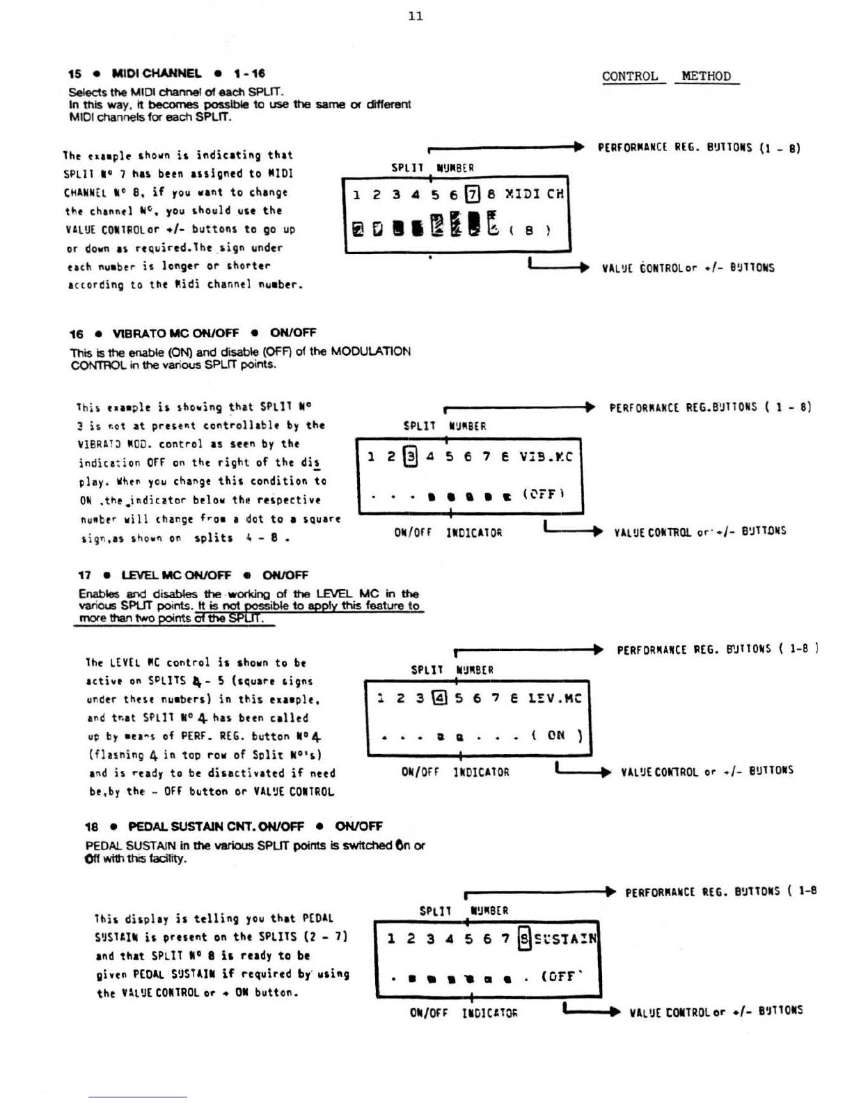
15
•
MIDI
CHANNEL
• 1 •
18
Selects
the
MIDI channel
of
eachSPLIT.
11
In
this way.
it
becomes
possible
to
use
the
same
or
different
MIDI channels
for
each SPLIT.
The
eaaaple sho
wn
is
indicating
that
SPLIT
W
0 7 has been
assigned
to
MIOl
C~ANNEL
W
0
8,
if
rou
wa
nt
to
change
the
ch
an
n
el
,
~
,
you
should use
the
VA
LUE
CONTROLor
•/-
buttons
to
go
up
or do
vn
as reQuired.
The
.
sign
under
each
nu
aber
is
longer
or
sh
ort
er
accor
di
ng
to
the
Mid
i channel nuaber.
SPL
ll
MUM
BE
R
123456{2)8
iCII~~~~
16
•
VIBRATO
MC
ON/OFF
e
ON/OFF
This is
the
enable
(ON)
and
disable (
OfF)
of
the
MODULATION
CONTROL in
the
various SPLIT points.
•
CO
NTR
OL
METH
OD
PERFORMAN
CE
REG.
BUllOMS
(1
- 8)
~IDl
CH
( e }
I .
VAL
UE
CONTR
O
Lor
•
/-
BUTTON
S
This eaaeple
is
showing
~h~t
SPLIT
N°
r1
--------+•
PERfORMANCE
REG
.
B'IJll
ONS ( 1 - 8)
~
is
r.ot at
present
controllable
by
the
~18RA
1J
M
OO
.
control
as seen
by
the
indica
tion
OFf
on
the
righ
t of
the
dis
-
play .
When
you
ch
ange
this
condit
ion
to
ON
,th
e.
indicator below the
respective
nu
abe
r w
il
l change
froa
a dot
to
a sQuare
sign,
as
shovn
on
splits
4 - 8 •
17
• LEVEL
MC
ON/OFF
•
ON/OFF
$PllT I
IJIIISER
•
1 2 A S 6 7 S V!S.Y.C
• • • • • a •
~
(Ci'F)
•
•
011
/
0H
11
01Cll01\
I.._
__
...
VALUE
COMTl!Ql
or·
•/-
8
U'Tl.O
II
S
E~
and
disables
the
.woc1dng
of
the
LEVEL
UC
in
the
various SPLIT
points
.
1t
is not W i
ble
to
apply
this
feature to
mor
e than
two
poi
nts
Of
the
SP
.
lhe
LEVEL
MC
control
is
shown
to
be
ac
tive
on
SP
L
ITS,_
S (sQuare
signs
u
nd
er these nuebers)
in
this
eaaeple,
a
nd
tr.at
SPLIT
11
° 4 has
bun
called
u~
by
au
~s
of
PERf.
REG.
button
10
4
(fla5ning 4 in top
row
of
Split
IIO's)
a
nd
is
ready
to
be
disact
ivated
if
need
be
,
by
the -Off b
utton
or
YAL~E
COilROL
•v--------·IIJo.
PERFORMAN
CE
REG.
B"JllOII
S ( 1
-8
)
SPLIT
II!JMBE
R
1 2 3 t!} S 6 7 E
L!V
.MC
• • • a a • • • (
ON
)
•
011/0ff
INDICATOR
'-1_.....,.....
YAL'.l£CON1RO
L or
•/
-
B!JlTOIIS
18
•
PEDAL
SUSTAIN
CNT.
ON/OFF
e
ON/OFF
PEDAL SUSTAIN in
the
various
SPUT
points
Is
switched
6n
or
Off
withthis facility.
i •
PERFORMAN
CE
REG.
81JTTOIS
( 1-8
th
is di
splay
is
telling
you
that
PEDAL
S~Slllll
is
present
on
the
SPLitS (2 -
7}
and
that
SPLit 10 8
i•
ready
to
be
SPLll
I!J"BER
viven
PEDAL
S!JSTAII
if
required
by·
usit~g
the
VlL
~[
COIIlROl
or •
01
button.
•
• a a • , a a •
(OfF
'
•
•
"''
--~··
YA
L
!JE
tOilROL
or
•/-
BIJT101
S
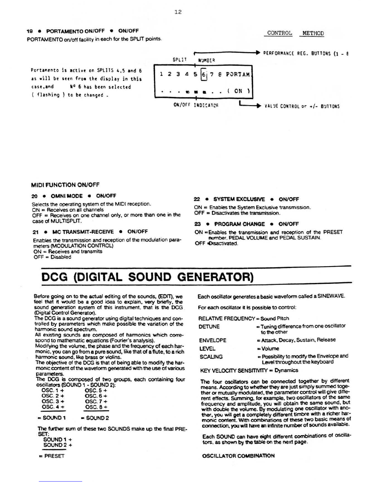
19
• PORTAMENTO ON/OFF • ON/OFF
PORTAMENTO on/offfacility in each for
the
SPLIT
points
.
12
CONTRO
L
METH
OD
r •
P£RfORM
t.HC£
REG.
BU
l lQ
tjS
(1 - 8
SPLll
II
~
'!S~
~
Porta~tnto
is
a
ctiv
e
on
SPLllS 4,S and 6
as vil l
be
sttn
fro•
tht
display in
this
l 2 3
.a
S
~
7 €
PORT
AM
· • . c • a • . (
ON
l
tas
e,and M
0 6 has been
stlttttd
(
fla~hing
)
to
bt
thangfd • •
•
0"
/O
FF
I
1101
CAl
~I:
~
..
---1.~
YA
l
~£
CONlR
OL
or
•/-
B
~
llOii
S
MIDI FUNCTION ON/OFF
20
•
OMNl
MODE • ON/OFF
Selects
the
operati
ng
system
of
the
MIDI reception.
ON = Receives on all channels
OFF = Receives on one channel only. or more than one in the
case
of MULT\SPLIT.
21
•
MC
TRANSMIT-RECEIVE • ON/OFF
Enables
the
transmission
and
reception of
the
modulation
para
·
mete~
(MODULATION CONTR
OL)
ON = Receives and transmits
OFF c Disabled
22
•
SYSI
EMEXCLUSIVE • ON/OFF
ON
-=
Enables
the
System Exclusive transmission.
OFF
• Oisactivates
the
transmission.
23
• PROGRAM CHANGE • ON/OFF
ON
•Enables
the
transmission
and
recept
io
n
of
the
PRESET
number
.
PEDAL
VOLUME
and
PEDAL
SUSTAIN.
OFF oOisactivated.
DCG
(DIGITAL
SOUND
GENERATOR)
Before
going
on
to
the
actual editing
of
the
sounds, (EDIT),
we
feel that
it
would be a
good
idea
to
explain, very briefly,
the
sound genef"ation system
of
th
is instrument.
that
is
the
DCG
(Digital
Cont
rol Generator).
The
OCG
is a sound generator using digitaltechniques and
con
·
trolled
by
paramete~
which make possible
the
variation
of
the
harmonic sound spectrum..
All existi
ng
sounds are
composed
of
harmon
ics
which
corre-
spond
to
mathemat
ic
equations (Fourier's analysis).
Modifying the volume,
the
phase
andthe frequency
of
eachhar-
monic,
you
cango froma puresound, like
that
of
a
flute
,
to
arich
harmonic
sound
. like brass orviolins.
The objective
of
the
DCG
is
that
of bei
ng
able
to
modifythehar-
moniccontentof
the
waveformgeneratedwith
the
useof various
parameters
.
The
OCG
is
composed
of
two
groups, each containing
four
osc
il
lators(SOUND 1 - SOUND
2)
:
osc., + osc.5 +
osc.2 + osc.6 +
osc.3 +
osc
.7 +
osc.
~
+ osc.8 +
•
SOUND
1 • SOUND2
The
f\.l'ther sum of these
two
SOUNDS make
up
the
final PRE-
SET:
SOUN01+
SOUN02
+
• PRESET
Eachoscillatorgeneratesa
basic
waveformcalled aSINEW
AVE.
For
each
oscillator
it
Ispossible
to
control:
RELATtVE FREQUENCY a
Sound
Pitch
OETUNE
ENVELOPE
LEVEL
SCALING
c Tuning differencefromone
os
cillator
to
the
other
c
Attadt,
Decay
, Sustain.Release
•Volume
..
Possblity
to
mod"rfy
the
Envelopeand
Level
throughout
the
keyboard
KEY
VELOCITY
SENSITMTY • Dynamics
The
four
oscitlators can
be
connected
together
by
different
means.
Acc:Ofding
to
whether
they
are
just
&imply summedtoge-
thef
or
mutuallymodulated,
the
parameter control will give diffe-
rent effects. Summing, for example,
two
oscillators
of
the same
frequency
and amplitude,
you
will
obta
in
the
~me
~d
.
but
with
double
the
volume.
By
modulating one
OSCillator
with
ano-
ther,
you will
get
a comp4etely different timbre
with~
richer har-
monic
content.Wcth combinations
of
ttoese
two
baSIC
me;ans
of
connection,you
wilt
have
an
Infinitenumber
of
soundsava•lable.
Each SOUND can have oigt1t cftfferent combinations
of
oscilla·
tors
.
as
shown
by
the
table
on
the
next
page
.
OSCILLATOR COMBlNATlON

13
"EDIT" PRESET PARAMETERS
This
function allows
y04JtO
modify
a
sound
already
programmeo.
theteby making
the
creation
of
new
ones
possible.
To
change
the
paramnn
of
a sound, you must press
the
EDIT
key
and
then
11tect
the
number
of the parameter
that
youintend
to
modify
.
display
.
-'OnQ
-.lth
the situation
of
the
e
ight
oscUla
tors
and,
lashing,which
of
the eight
that
il
reedy
to
be
modified.
Under
eiCh
osc:iftator, some
~
deSigns
W1
11
always
be
lhown
.
in
order
to
fqep
all
the
eight
valueS
under
c:outrolat
the
eame
time.
The
parametersfrom
1·12
rwfef
to
the
eight
oscillators. whilethe
numbers
from
21·38
cooaspond
to
SOUND 1
and
SOUND
2. By
means
of
the
buttonsfrom 1
to
8 of
the
PERFORMANCE
REGI·
STRA
noNS.select
one
of
theeight oseillatO'$
to
be
modified
[r1
the eetected parameters are
between
1·12
Inclusive).
At
this
point
the
name
of
the
paranwter
chosen
will
be
shown
on
the
If
the
parameter
to
be
modified
"-'ers
to
the
SOUND
(from
21
to
38),
then
the
firs1
two PERFORMANCE REGISTRATlOHS
but·
tons
are
used
to
select
SOUND
1 or SOUND 2. Ai5o in
this
case
the
one
in
operation
will
be
seen
to
flash
.
It
,hould
be n
ot
ed
that
whe n w
orking
w
ith
the
EDIT
PARAMETERS
fro•
1 -
12
,
the
lower
lin
e
of
PERFORMANCE
REG
ISTRATIO N
buttons
9 -
16,
can
be
used
to
canc
el
the
8
oscillat-ors.
Button
N
°9
for
OSCIL
L
ATOR
No 1, But t
on
N°10 f or
OSCILL
AT
OR
.
11
c 2 an d s o
on
. 1he os c i
lla
t or s s wi t -
ched
off
w
ill
be shown by
the
abse
nse
of
t
heir
nu•bers
in
the
top
line
of
the
displays
of
Para•eters
1 - 12 and whe n you
have
canc
el -
led
,
an
oscillator
whi l e wo
rk
ing
on
one
particular
paraaeter,this
w
ill
of
co
urse
show
off
on
all
the
displays
relative
to
Para•eters
.
1 - 12 •
On pr
essing
EOil
,
the
follo
w
ing
display
r-----------------------------~
w
ill
show : -
SOUND
EDIT
Parameter
? : 1
CONTROL·
M
ETHOD
You
•
u~t
no w
press
the
nu•ber
of
t~e
E011
PA~A"ETER
th
at you
want
to
a
odify,
u~i~g
the
PARAMETER
SELECTOR
~ey
pad,
1
L-----·
..
PAR
AM
ETER
SELECTOR
then
[In£
and
then
pr
ess
EllER
.
OSCIU
ATOR CONTROL
1 e RELATIVE FREQUENCY •
0.S
•
15
This
paraaeter
enabl
es
you
to
a
djust
the
RELATIVE
FR
EO~E
N
CY(Pi~ch)
of
the
oscillators~
a
ault
iple
of
between
0.
5
and
15
.
This
·~a
ns
that
,if
fo
r
exaa
ple
,y
ou
•
odif
y a
note
of
A-440
Hz
by a
a
ultiple
of
O
.S,t
hen
the
fr
equency
will
becoae
220
Hz( o
ne
octave
lo
w
er).If
by
the
sa•e
token
you
cha
nge
this
note
by_a f
actor
of
2,then
it
w
ill
beco
a e
880
Hz(one
octave
higher
than
the
standard
pitch)
,
and
so
on.
this
display
is
s
hoving
that
OSC.N°8
(flashing)has
been
set
to
3
,•ean
ing,
as
explained
above,that
this
oscil
-
l
at
or w
ill
sound
at
a
freq
ue
ncy,
three
tiaes
high
er
than
nor
•al
(
for
A-440,
this
•eans
a
frequency
of
1320Hz.
N.B.-
T
his
is
not
3
oct
ave
s
highe
r ,
w
hich
would
aea
n
•ultiplying
by a
factor
of
8(for
A·440,
3
octaves
higher
aeans
a
frequency
of
3,520
Hz.)
r-.---------+•
PERFORMAN
CE
REG.
B
~llON
S(
l-
8)
•
1234567(il
FREQ.
-•-
--
·-· ( 3 )
'
GRA
PHIC
VALUE
INDICATOR
I\..--~·~
VA
L!JE
..CO
VTRO
L
or
•I
-
B'JlTON
S

14
2 • DETVNE • • 3 + 3
The
osc
illator freQuency determ&
ned
by
the
REl.A'TlVE
FRE·
OUENCY control. can be very
sl
i
ghty
retuned
by
means
of
this
fine
tun
i
ng
cont
rol. to
obta
in some
usefu
l beati
ng
effects
.
+ 3 Pos
rti
ve
Oe
tuning (sh
arp
)
0
Re
lative Frequency
- 3
Nega
tive Oetuning (f\at)
rROL M
ETHOD
The
flashing
N° 4 in
this
display
ex
a•ple
is
in
dic
a
ting
th
at
OSC.
N° 4,v
hith
at
present
i s
at
a •axi• u• detuning l evel of
-3
as shov
n,
is
re
ady
to
be
d
et
un
ed d
iff
ere
ntly
as re
quir
ed.
The
detuning of
ei
ch
oscilla
tor can be
rea
dil
y
r----------·
PERFOR
MAN
CE
R[G
. B
!JTlO
!IS
(
1-£<
)
123
1j
5678
DE
TUNE
<-
3 )
seen
to
be
!JP
or
DO
WN
by
the
signs
unde
r each
L-----------------------~----.J
oscill
ator
nu
aber.on the bottom
line.
UP/DO
WN
IN
DICATOR
\..I--~~~
VAL!JE
CO
N
TROL
or • /- B
!JTTO
NS
3 • ENVELOPE ATTACK
RATE
• 0 •
31
Varies
the
time.taken by
the
envelo
pe
prof
il
e.
to
go from 0
to
i
f
~
•
m
axi
m
um
level,
af'tef
the
ke
y h
as
bee
n pressed.
0
'""
M
tnt
mum
speed
31
c:
Max
tmum
speed
••••••••
PERFOR
MAN
CE
REG.
B!JTTO
NS (1-8)
A
TT
A
CK
(
15
)
-..-
OSCil
lAT
ORS
3
an
d 6 are
cancelled
in
this
display
,
and
N° 5
ha
s
it's
EN
VELOP£
A
TT
A
CK
RATE
set
to
l5,
ab
out
half
w
ay
of
it's
•
a~
i• u•
atta
ck ra
te,as
s
ho
wn
by
the
sign under
t he
nu
mber 5.
GRAP
H
IC
VA
LUE
IN
DIC
A
TOR
L'----~~
VAL
!JE
CO
N
TROL
or
+/-
B
1
JTTON
S
4 • ENVELOPE DECAY RATE • 0 •
31
Controls
the ti
me
necessary for
the
enve
lo
pe
pr
ofileto
pass
from
it's
maJtt
mum
level to
tha
t of
the
SUSTAIN.
0 c M
&ntmum
speed
31 •
Max
&mum
speed
.----------_.
PERFOR
MAN
CE
REG.
B!JTTO
II
S (1-8)
The
EN
VEL
OPE
DECAY
RA
TE
of
OSC
. w
c2
is
se
t
to 6 in
this
case,and can be a
odified
as
is
shown
by
the
f
la
~hin
g
N° 2.
l
1
t;
• A 5 • • 8
DECAY
--······
(
6)
•
ilSClllAT
ORS
3,
6a
nd
7 are
sho
wn
to
be
s
wi
tched
off
by
the
fact t hat t
heir
nu•
bers
do n
ot
appear
on
the t
op
line
of
the dis
play.
GRAPH
IC
V
AL~E
l~
OIC
A
TOR
'-
1
--~~~
V A
L~E
CON
TROL
or +/-
B'JTTO
NS
5 e ENVELOPESUSTAIN LEVEL • 0
·15
Determ•l'\eS
the
constant
en
ve
lo
pe
le
vel or vo
lu
me at which the
sound
is
m.a
intamed to
compl
ete the
ATIA
CK
and
DECAY p
ha·
ses
for
the
total ti
me
thatthe
not
e
key
is
ke
pt
pressed
.
Ln
such
a case.
though.
whefe t
f\e
SUSTAIN
RA
TE value
is
not
zero.
the
n
the
SUSTAIN
LEVE
L
create
s some
mo
re
co
mplex
trans
ie
nt
s
of
DECAY (pizzicato.
et
c.) indica
ting
the
brea
king
po
in
t
between
DECA
Y
RATE
and
SUSTAIN
RA
TE.
0 •
Zer
o
vol
ume
.
15 =Maximum
vo
lume
.
Fro•
this
display
you
can see
that
OSC.
N° 4
has
an
EN
VELOPE
S~ST
A
I
N
LEVEL
of 12,as
is
shown
by
th
e nuaber in bra
ck
e
ts
a
nd
also
h
ere
you
can see
that
OSC
I
LL
ATORS
3,6
a
nd
7
have
been cance
ll
ed
.
--
PERFOR
MAN
CE
REG.
BUTTONS
(l-8
SUSLEVL
·····-
(
12
)
GRAPHIC
VA
L
UE
I•
OIC
A
TOR
1-l
--
-~·
VA
L~E
CO
N
TROL
or +
/-
B
~lTO
N S
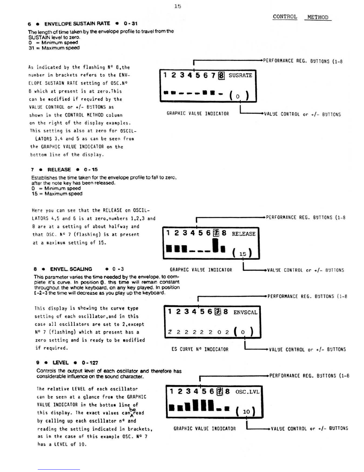
6 e ENVELOPE SUSTAIN
RA
TE
• 0 • 31
1lle
length
of
ti
me
taken
by
the enve
lo
pe
profileto travel from
the
SUSTAIN l
evel
to
zero.
0 = Minimum speed
31
~Maximum
speed
15
CONTROL
METH
OD
r-----------
PERFORMAN
CE
REG
.
B~lTONS
{1-8
As
indicated
by
the
flashing
N° S
,t
he
number
in
brackets
refers
to the
ENV
-
ELOPE
SUSTAI
N
RATE
setting
of
OSC
. N°
8
whi
ch
at
present
is
at
zero.This
can
be
•od
ified
if
re
quir
ed
by
·
th
e
VA
L~E
CO
N
TROL
or +
/-
B~TTO
N S
as
shown in the
CO
NTR
OL
M
ETHOD
coluan
on
the
rig
ht
of the
display
exaa
ples.
This
setting
is
als
o
at
zero
for
OS
CIL-
l
ATORS
3,4
and
5 as can
be
seen
fro•
the
GRAPHIC
VA
LUE
IND
IC
ATOR
on
the
bottoa
line
of
the
display
.
7 • RELEASE • 0 - 15
1 2 3 4 5 6 7
f@1
SUSRATE
··---··-
( 0 }
GRAPH
IC
VAL
UE
IN
DIC
A
TOR
'"'---•
VA
L'JE
CONTROL
or
•/
- B
!JTTO
NS
Establishes t
he
ti
me
ta
ken
for
the
envelo
pe
p
ro
file
to
fa
ll to zero,
after
the
note key has been released.
0 = Mi
nimum
speed
15
=
Maximum
speed
Here
you
can see that the
RELEA
SE
on
OSCIL-
.
LATORS
4,5
and
6
is
at
zero,nua
bers
1,2,
3
and
r----------
PERFOR
MAN
CE
REG.
B!JTTONS
(1-8
8
are
at
a
setting
of about
half
w
ay
and
that
OSC.
N° 7
(flashing)
is
at
present
1
23456
~
8
RE
LE
ASE
at a m
2xi
mum
sett
ing of 15.
··---
I
8 • E
NVEL
SCALI
NG • 0
-3
GRA
PHIC
VA
LUE
INDIC
ATOR
~L---•
VA
L
'J
E
CONTROL
or
+/-
B'JTTON
S
Th
is parameter varies
the
time
needed
by
the
envelope. to
com-
plete
it's
curve. In
pos
ition 0.
th
is
time
will remain constant
t
hrou
ghout
the
whole
keyboard.
on
any
key
played
. In
position
l-2-3
the
t
ime
will decrease as you
play
up
the
keyboard.
r----------
PERFORMAN
CE
REG
.
B'JTTONS
(1-8
This
display
is
s
ho
~
ing
the curve type
settin9
of
ea
ch
oscill
ator
,
and
in
this
case
all
oscil
lators
are
set
to
2,except
N°
7
(flash
ing)
which
at
pr
esent
ha
s a
ze
ro
sett
i
ng
and
is
ready
to
be
a
odifi
ed
if
requir
ed
.
9 •
LEVEL
• 0 • 127
1 2 3 4 .5 6
{1J
8
ENVSCAL
2'22222o2
(
o_
}
ES
CURV
E
N°
IN
DIC
AT
OR
IL
---•
VALUE
CONTROL
or •
I-
BUTT
ONS
Controls the output level
of
each
oscillator
and
therefore
has
considerable influence
on
the
sound
character
.
r----------
PERFORMAN
CE
REG.
B
'.l
llONS
{1
-8
Th
e
relative
LEVEL
of
each
oscillator
can
be
seen
at
a glance
fr
o• the GRA
PH
IC
VALUE
IN
DIC
AT
OR
in
the
bott
o•
line
of
this
display.
The
ex
a
ct
values
can~ead
by
calling
up
each
oscil
l
ator
n°
and
reading the
setting
indicated
in
bra
c
kets,
as
in
the case of
this
exa•ple
OSC
.
N°
7
has a
LEVE
L of 10.
123456
lJJ
8
OSC.LVL
··•11
-·
GRAPHIC
VAL'.IE
IN
DIC
A
TOR
IL
---•
VALUE
CONTR
OL
or
+I-
BU
TTO
NS
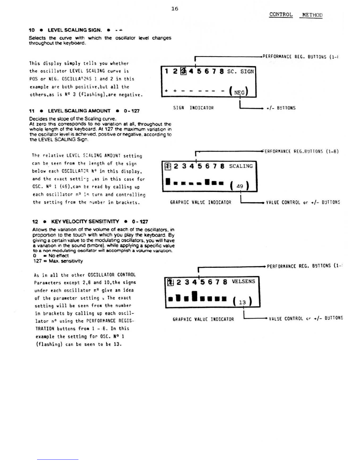
10
e LEVEL
SCAUN
G SIGN. • - •
Selects
the
curve
with
wh
i
ch
t
he
oscillator
le
vel
changes
throughout
the
keybOard.
16
CONTROL
METH
OD
r----------
PERFORKANCE
REG.
B\lllONS
(1-1
This display
si•ply
tells
you
w
hether
the
oscillator
LEVEL
SCALING
curve
is
1 2 4 5 6 7 8
SC.
SIGN
PO
S or
NE
G.
OSCILLA
10hS 1
and
2
in
this
exaaple
are
both
po
~
itive,but
all
the
others.as
is
N°
3
(f!ashing
)
.are
negative.
++
-
----
11
e LEVEL SCALING AMOUNT •
0-
127
Dec
i
des
the
slope
of
the
Sca
li
ng
curve.
At zero
thes
corresponds
to
no
variati
on
at all.
throughout
the
whole
length
of
the
keyboard
.
At
127
the
maximum
variati
on
ir1
the
oscillator level
is
ache•ved.
posit
ive
or
negative.a
ccord
i
ng
tCI
the
LEVEL
SCALING
Segn
.
S
IGN
INOICt.TOR
l'----••
+/-
B
t!
llONS
T
~
e
rela
tive
LEV
EL 5
:ALIN
G
AMO
\l
Nl
setting
can
be
seen
fro•
the length of
the
sig
n
be
l
ow
ea
ch
OS
C
IL
L Al
~~
N° in
this
display.
and
the
exact
sett:-:
,as
in
this
case for
O
SC
.
N°
1
(49),can
~e
read
by
calling
up
each osc i
llator
n
~
:r.
turn
and
controlling
the
st~ting
fro•
the
numbe
r in
brackets.
,._..--------.-;.
-ERFORKANCE
R£G.
B'J
1TON
S
{1-B
)
•
[!j
2345678
SC
ALING
···--···
GRAPHIC
VAL'JE
INOICAlOR
I""
---•
VALUE
CO
N
TROL
or +/-
B'JTTONS
12 • KEY VELOCITY SENSfTIVITY • 0 -
12
7
Allows
the
variati
on
of
the
volume
of
each
of
the
oscillators.
in
proporteon
to
the
touch
with
which
you
play
the
keyboard. By
givi
ng
a
certa
in value
to
the
modulat
i
ng
oscillators.
you
will
have
a
vanat
e
on
in
the
sound
(t
embre).
whi
le applying a
specific
value
to
e
t"'()n
modulating
oscillator
wm
accomplish
a
volume
variat•on.
0 •
No
effect
, 27 -Max.
~srtivfty
..---------,.
PERFORMANCE
REG.
B'JTTONS
(1-
:
As
in
all
the
other
OSCILLATOR
CO
N
TROL
Para•eter
s except 2, 8
and
lO,the
signs
under each
oscillator
n°
give
an
idea
of
the
pa
r
aaeter
setting
,
The
exact
setting
will
be
seen
fr
o•
th~
nu•ber
in brackets
by
calling
up
each
oscil-
l
ator
no
using
the
PERFOR~ANCE
REGIS-
TRATION
buttons
fro•
1 - ·
B.
In
this
exa•ple
the
setting
for
OSC. N° 1
(flashing)
can
be
seen
to
be
13.
00
2 3 4
'5
6 7 8
••
•I
••••
VE
L
SENS
'
GRAPHIC
VALUE
IMOlCATOR
'Lo---••
VAL!JE
CONTROL
er
+/-
B!JTTONS
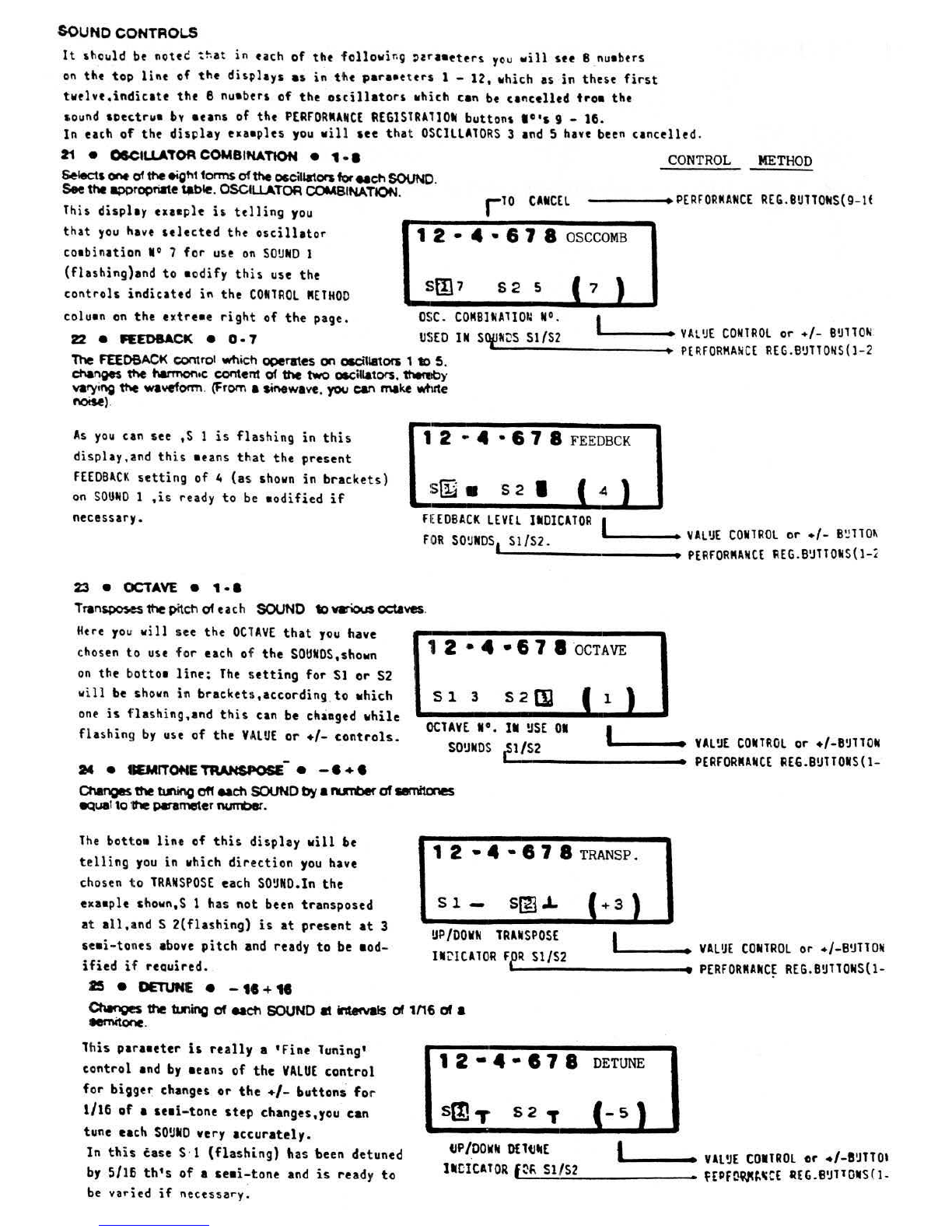
SOUND CONTROLS
It
sho~ld
be
notec
~~at
in
each
of
the following
'araaeters
you
will
see 8 nuabers
on
the
to~
lint
of
the
displays
as
in
the
para•eters
1 -
12,
which
as
in
these
first
twelve,indicate
the 8 nuabers
of
the
oscillators
which can
be
cancelled
troa
the
sound soectrua
bv
aeans
of
the
PERFORMANCE
REGlSlRAliON
buttons 1o•s 9 - 16.
In
each
of
the
display
e•a•ples
you
will
see
that
OSCILLATORS
3
and
S
have
been
cancelled.
21 e
OSCII
I
ATOf'
COMBINAT10N
e
1·
8 CONTROL METHOD
Selects~
of
the
eight
forms
of
the
occil'-tors
for
each
SOUND
.
See
the
~~tiate
tJble.
OSCtlt
ATOR COMBINATION.
This display exaeple
is
telling
you
----•
P[RFORMAtiCE
fi£G.8UTTOIIS(9-lt
that
you
have
selected
the
oscillator
coabination
N°
7
for
use
on
SOUND
1
(flashing)and
to
aodify
this
use the
controls
indicated
in
the
CONtROL
RElHO
O
coluan
on
the
extreae
right
of
the page.
22 •
F££08ACK
• 0 • 7
1 2 • 4 • 6 7 8
OSCCOMB
s 2 5
OSC.
COMBitiAllOU
N°.
USED
IN
sqpw~s
Sl/S2
7
The
FEEOSACK
c:omrot
which operates
on
a.cmators 1
to
S.
changes
the
harmon•c
content
of 1he two oacillators. thereby
varying
the
wavefOttil
.
(from
a Sinewave. you
can
make wtute
noise).
I
'-----•
VAL
'J
E
CONTROL
or
•I-
BUlT
ON.
•
PERFORKA~C[
R[G.BUllONS
(l-2
As
you
can see ,S 1
is
flashing
in
this
display,and
this
aeans
that
the
present
FEEDBACK
setting
of
4 (as
shown
in
brackets)
~n
SO
UND
1
,is
ready
to
be
aodified
if
necessary.
23
• OCTAVE e
1·8
1 2 • 4 • 6 7 8
FEEDBCK
sffi •
s2
I 1
FEEDBACK
lEVEl
IIIDICATOR
l
___
,.
- •
VAL~E
CONTROL
or
•f-
8~110~
FOR
SO!JNDSL&
-5
-1
-/S-
2
-·
-------•
PERFORMANCE
REG.
B!JllOtiS{l-i
Trans;>oses the
pitch
of
each SOUND
to
various octaves.
Here
yo
u
will
see
the
OC
T
AVE
that
you
have 1 2 • 4 • 6 7 I ·
acTA
VE
chosen
to
use
for
each
of
the
SOUNOS,shown
on
the bottoa
line;
The
setting
for
SI
or
S2
will
be
shown
in
brackets,according
.
to
which
one
is
flashing,and
this
can
be
changed
vhile
fl ashing
by
use
of
the
VALUE
or
+/-
controls.
-
24 • TRAHSPOSE • - e+ e
s 1 3
S2DJ
1
OClAVE
11°.
IN
USE
01 I
L----•
VALUE
COIHRQL
or
+/-B!JTlON
SO'JNDS
L:_lf_S_2
______
_
~
•
PERFORMANCE
REG.BUlTONS(l-
Changes
the
U\ing
oft
each
SOUND
by
a
ftUl'Tt)ef
of
sem.'tones
~uat
to
the
perameter
number.
The
bottoa
line
of
this
display
will
be
telling
you
in
which
direction
you
have
chosen
to
TRANSPOSE
each
SO!JNO.tn
the
eKaaple
shown,S
1 has
not
been transposed
at
all,and
S
2(flashing)
is
at
present
at
3
seai-tones
above
pitch
and ready
to
be aod-
ified
if
reQuired.
15
•
DETUNE
e -
1e
+
11
1 2 • 4 • I 7 8 TRANSP.
Sl-
S(ID
..L
+3
UP/OOVN
TRANSPOSE
I
L---••
VAL!JE
COiilROL
or
+/-B!.ITTOII
liiL'lCAlOR
FfLR_S_l_fS_
2
______
....
PERFORMANCE
REG.B!JllONSll-
.
Ctwnge$
the
tuning
of
eaeh
SOUND
8l
irdel"vaas
of
1116
of
a
let"nitone.
This
paraaeter
is
really
a
'fine
Tuning'
control
and
by
aeans
of
the
VALUE
control
for
biige~
changes
or
the
+/-
buttons
for
l/16
of
a
seai-tone
step
changes,you can
tune each
SOUND
very
accurately.
ln
th
is case S· l
(flashing)
has been detuned
by
S/16
th's
of
a
se•i-tone
and
is
ready
to
.
be
varied
if
necessary.
12•4•178
DE
TUNE
s[llT
S2
T
-5
liP/.
OOVN
OElliiiE(
&----•
Vll!JE
COIITROL
or
•/-8~110.
nr:I
cu
ORF
L:.;."~s
I:.::t..:;s.:..2
------·
HP
r
~q,pcf.
~
c£
RE
G•e
'J
11
o11s
(I-
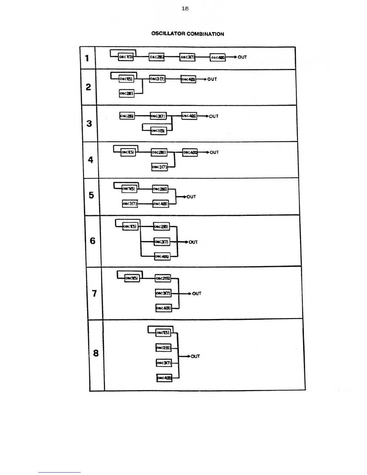
18
OSCU I ATOR COMBINATION
1 I
(oa
c
1(~}
{
o
~
c
~
loa
c
xr~
(oac
111'1}
•OUT
I
Kl5
)
01
OUT
2
215
\
"K2R
._.,
C
4CBI
OUT
3
1(5J
r-
1
51
~
I
OUT
4 3
01
l .
...,
)
:I
2IQ
5 "T
pec3
(7)
c
.CS
)
-u l
2e
l
6
''!
OUT
·-
oec:1C5I
7
~3('7)
OUT
.....
,
OK'tS
l
tl
(6
8
OUT
31'7
·
at

26 • PfTCH ENVELOPE
ATTAC
K • 0 - 127
l~
Varies
the
PITCH En
ve
lo
pe risi
ng
speed
, when
types
1
to
3 have
bee
n
~ed
.
CO
NTROL
ME
THOD
0
..
No
eff
ect
1 c Minim
um
speed
127 • Maxim
um
speed
Th
e
PIT
CH E
NV
ELOPE
ATTA
CK
on
S 2(
fla
shing)
has b
een
set
to
B2
in
th
is
e
xa
•
ple,an
d
can be •
odified
i f req
ui
red.
If
you w
ant
to
see the exact se
ttin
g of S
1,th
en j
us
t
press
PERFOR
MAN
CE
REGIS
T
RATION
button No 1
and
the
settinQ
w
ill
show in the b
rackets.
27
•
PITCH
ENVELOPE
DE
CAY • 0 •
127
Co
nt
ro
ls
t
he
falling
speed
of
the
PITCH Envelope.
In
this
exa•ple
the
PI
TCH
E
NV
ELOPE
DECAY
of
SO~
N
O
1
(flashing
)is
shown
to
be
set
at
60
,
this
of
cou
r
se
can be •
odified
if
needed
by
•eans
of
th
e
controls
in the
CO
N
TROL
M
ETHOD
colu•n
on
the
right
.
28
•
PIT
CH
ENVELOPE
LEVEL •
0-
127
PCH . A
TT
s 1 I sfil I
s2
PITCH
A
TT
A
CK
INDICA
TOR
''----
..
F
OR
SOU
NO 1 a
nd
2 · •
VAL~E
CO
N
TROL
or +/- BU
TTON
S
"----------
PERFOR
MAN
CE
REG.BUTTON
S(1-2)
1 2 • 4
li
6 7 8
PCH.
DEC
s m I s 2 1
60
PIT
CH
DEC
AY
lN
DICAlOR
FOR
SO~
N
O
1 a
nd
2
L'----•
VAL~E
CONTROL
or
•/-
BUTTON
S
'--
-
------
--+
PERFOR
MAN
CE
REG.B
1
JTTO
NS
(l
- 2)
Vari
es
the amount of c
hange
in
fr
e
que
ncy
decided
by
the
PITCH
ENVELOPE
.
Fro• the
displa
y i n t his
ex
a
mp
l e y
ou
w
ill
see t
hat
the
PITCH
EN
VELOPE
LE
V
EL
for
SO~NO
2 has been
set
to
0 . T
his
can
be
varied
if
necessary or
if
y
ou
w
an
t
to
see
the e
xa
ct
setting
of t
his
Level
on
SOU
ND 1,
then press
PERFOR
MAN
CE
REG
I
STRATIO
N N° 1
and
the
setting
w
ill
be shown i n br
ac
ke
ts
.
29 •
PIT
CH
ENVELOPE
TYPE • 1 • 4
1 2 • 4 • 6 7 8 PCH.
LVL
S 1 8 S
ml
- 0
PIT
CH
EN
VELOPE
LE
V
EL
I
IN
DICA
TOR
FOR
S 1
and
S 2
L----•
VA
L~E
CON
TROL
or +
/-
BUTTO
NS
'-------
----
...
PERFOR
M
AN
CE
R
EG.B~TTO
N
S(l-2)
Dec
ides
the
cu
rv
e
wi
1h
wh
ich
the
PIT
CH
ENVE.L.OPE
changes
the
frequency.
SO~
N
D
1 in
this
displ
ay will
be
controlled
by
curve N° 2 as
is
shown in b
rac
k
ets
.
and
to
the
right
of
the
S 1 sy•bol which
is
flashing
,•
eaning
that
t
be
:curve can
be
changed
if
felt
to
be n
ecessary
.
1 = 2 =
1 2 • 4 • 6 7 8
PCH.
TYP
s
~
2 s 2 3 ( 2 1
PITCH
EN
VELOPE
C
~R
V E
AL
LOC
AT
IO
N
lN
D.
F
OR
S1/S2
3 =
(._
____
,
VA
L'JE
CO
N
TROL
or +i-
BUTTO
NS
•
PE
R
FOR
M
AN
CE
R
E~.BUTTO
N
S(l-2)
4 =
Table of contents
Other Elka Synthesizer manuals


