Elmec EVC30T User manual
User Manual
ELECTRICAL VEHICLE CHARGING STATION LEVEL 2
EVC30T/EVC30T-IN
ELMEC Inc.
Rev.: June 2016

TABLE OF CONTENTS
Overview
(Models 4, 5, 30 and 31)
2
Parts List
3
Specications
4
Important Safety Instructions
5-6
Physical Installations
(Models 5 and 31)
7
Physical Installations
(Models 4 and 30)
8
Electrical Connections
9
Operation Sequence
10
Operating Modes
(Instantaneous Charging)
11
Maintenance and Cleaning
Storage of the Portable Version
12
Troubleshooting
13
Elmec Inc. Limited Warranty
14
Contact Us
15
1

2
The Elmec Inc. EVC30T/EVC30T-IN is a Level 2 Electrical Vehicle Charging Station. Its primary function is to send electrical power
to an electric vehicle that is equipped with the SAE J1772TM Electric Vehicle connector. There are different models of this charging station:
Can be used in wet location (UL/CSA type 3R, 4, 4X enclosure)
25’ (7.6 m) Output Cable SAE J1772TM
30A Output Current (40A circuit breaker)
Electrical installation require a junction box
Fixed and permanent installation
Can be used in wet location (UL/CSA type 3R, 4, 4X enclosure)
25’ (7.6 m) Output Cable SAE J1772TM
30A Output Current (40A circuit breaker)
Electrical installation with a NEMA 6-50P 240V plug on input cable
Portable model, non-permanent installation
MODEL MODEL
4 5
OVERVIEW
Can be used in wet location (UL/CSA type 3R, 4, 4X enclosure)
15’ (4.6 m) Output Cable SAE J1772TM
30A Output Current (40A circuit breaker)
Electrical installation require a junction box
Fixed and permanent installation
Can be used in wet location (UL/CSA type 3R, 4, 4X enclosure)
15’ (4.6 m) Output Cable SAE J1772TM
30A Output Current (40A circuit breaker)
Electrical installation with a NEMA 6-50P 240V plug on input cable
Portable model, non-permanent installation
MODEL MODEL
30 31

3
PARTS LIST
ANEMA 6-50P 240V connector (optional)
BUnit transport handle
CEnclosure
DSAE J1772TM electric vehicle connector
ESAE J1772TM connector’s release button
FElectric vehicle charging cable
WARNING !!!
DO NOT REMOVE THE BOLTS
THAT HOLD THE ALUMINUM
HANDLE ONTO THE ENCLOSURE
OF THE CHARGING STATION
Figure 2.1: Electric Vehicle Charging Station
(EVC30T Portable version shown)
B
A
C
D
E
F

4
SPECIFICATIONS
Input voltage
208-240VAC single phase, 30A Level 2 EVSE
Input connector
NEMA 6-50P (models 21, 31, 5 and 7);
wall-mount junction box connection
(models 4 and 30)
Output connector
SAE J1772TM
choice of 3 dierent cable lengths: 15’ (4.6 m), 18’ (5.5 m), 25’ (7.6 m)
Operating temperature
-40 °C to 40 °C
Storage temperature
-40 °C to 100 °C
Weight
4.5 kg (10 lb)
Dimensions (Height x Width x Depth)
(17’’ x 10’’ x 41⁄4’’)
Weather resistant
All models
For outdoor use
Models 4, 5, 30 and 31
(UL/CSA enclosure Type 3R, 4, 4x)
5
IMPORTANT SAFETY INSTRUCTIONS
SAVE THESE INSTRUCTIONS
This manual contains important instructions for the Elmec Inc. EVC30T/EVC30T-IN EV Charging Station
that should be followed during installation, operation and maintenance of the unit.
CAUTION
• To reduce the risk of re, connect only to a circuit provided
with 40 amperes maximum branch circuit over current
protection in accordance with the National Electrical Code,
ANSI/NFPA 70 and C.E.C Part 1 C22.1-12.
• This equipment should be used with an electrically interlocked ventilating
means during indoor charging of vehicles requiring ventilation during charging.
Verify that:
1) The ventilating means is operating properly.
2) The ventilation path is free of obstructions.
• Do not alter AC cord or plug provided. – Where it does not t the outlet, have proper
outlet installed by a qualied electrician. Improper connection increases the risk of an electric shock.

6
GROUNDING AND AC POWER CORD
CONNECTION INSTRUCTIONS
Read this manual thoroughly and make sure you understand the procedures before you attempt to operate this equipment.
The purpose of this manual is to provide you with information necessary to safely operate, maintain, and troubleshoot
this equipment. Keep this manual for future reference.
This equipment should be installed, adjusted, and serviced by qualied electrical personnel familiar with the construction and
operation of this type of equipment and the hazards involved. Failure to observe this precaution could result in death
or severe injury.
Do not use this product if the Electric Vehicle Charging Cable has any indication of damage.
Do not use this product if the enclosure or the Electric Vehicle Charging Cable Connector is broken, cracked, open,
or shows any other indication of damage.
This Electrical Vehicle Charging Station is intended for use with plug-in electric vehicles only.
Charger should be grounded to reduce risk of electric shock. Charger is equipped with an electric cord having an
equipment-grounding conductor and a grounding plug. The plug should be plugged into an outlet that is properly
installed and grounded in accordance with all local codes and ordinances.
IMPORTANT SAFETY INSTRUCTIONS
7
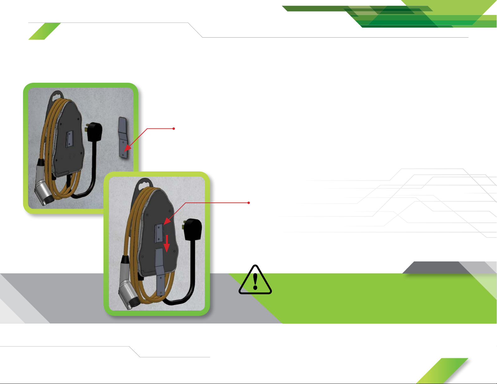
PHYSICAL INSTALLATION
Models 5 and 31
(with NEMA 6-50P plug connector)
This version of the Electrical Vehicle Charging Station is a portable-type
charger and is not designed to be xed permanently on a wall. But, using
our wall mounting kit, it is possible to mount the unit temporarily on a wall.
The Figure 5.1.1 illustrates this mounting kit.
Figure 5.1.1: Portable unit wall mounting kit
The wall mounting kit must be installed on a wall and xed on a
vertical stud that can support at least 4 times the weight
of the unit (the unit weighs about 10 lb).
Wall
bracket
Insert the unit on
the wall bracket
8
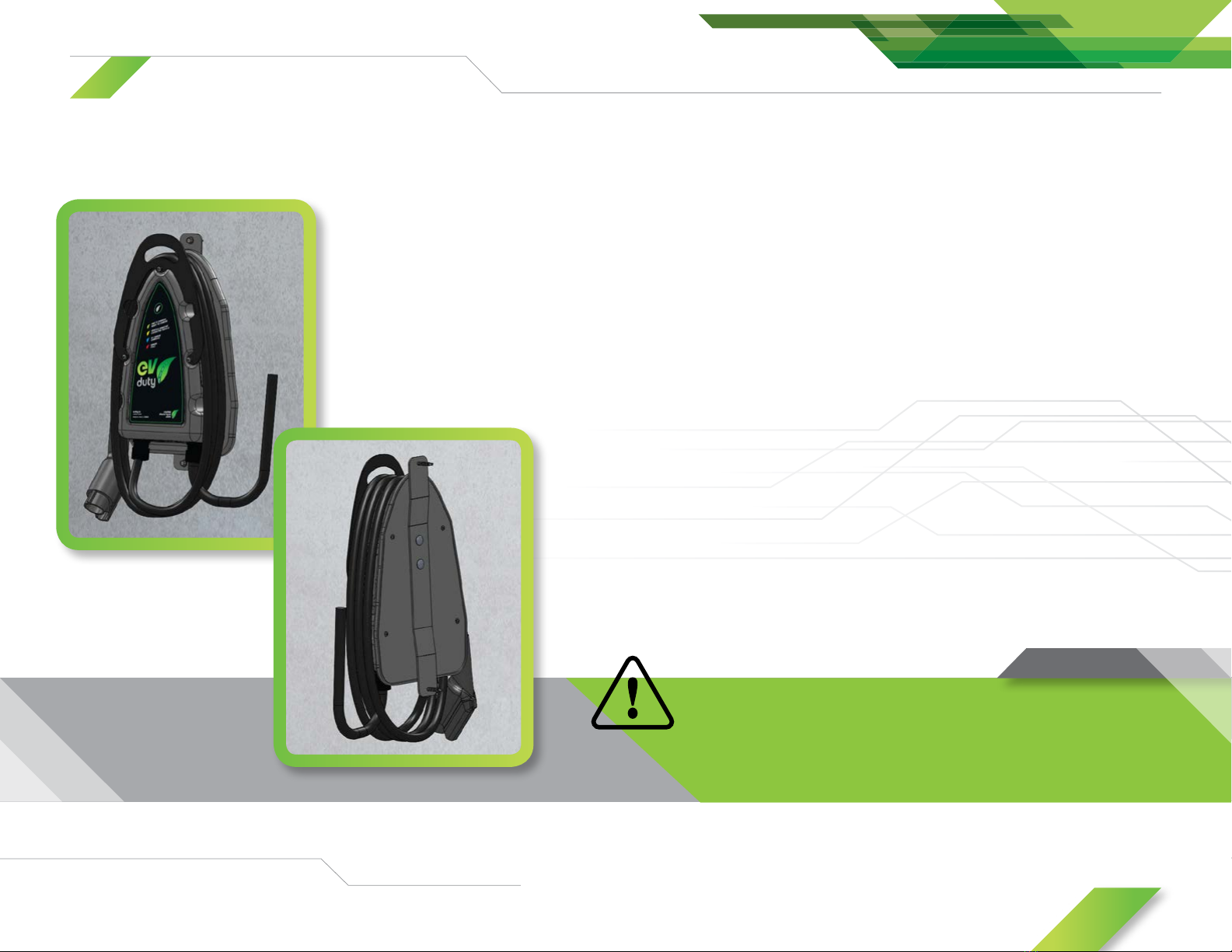
Figure 5.2.1: Fixed installation mounting kit
Models 4 and 30
(using a nearby installed junction box)
This version of the Electrical Vehicle Charging Station is a xed-type
charger and is designed to be xed permanently on a wall using the
mounting kit included with the charging station. The Figure 5.2.1 illustrates
this mounting kit.
The wall mounting kit must be installed on a wall and xed on a
vertical stud that can support at least 4 times the weight
of the unit (the unit weighs about 10 lb).
PHYSICAL INSTALLATION

9
Connection Table
Description Cable from the main
electrical panel
Cable from
charging station
L1 Black Black
L2 Red White
Neutral White N/A
Ground (Bare copper wire) Green
ELECTRICAL CONNECTION
Models 5 and 31
(with NEMA 6-50P power input connector)
1. Simply connect the NEMA 6-50P connector into a suitable
240V/40A receptacle.
2. Once the unit is receiving power, the Main LED will light up GREEN.
Models 4 and 30
(using a nearby installed junction box)
1. Install a junction box close to the location where you want to install the
charging station permanently.
2. Insert the cable coming for the main electrical panel into the junction box.
Information: Consult a qualified master electrician so he can calculate
the required size of the cable coming from the main electrical panel.
3. Insert the main input cable coming from the charging station into
the junction box.
4. Do the following connections:
This Electrical Vehicle Charging Station
requires a dedicated 40A in the main
electrical panel.
This equipment should be installed, adjusted, and serviced by qualied
electrical personnel familiar with the construction and operation of this type of
equipment and the hazards involved. Failure to observe this precaution could result
in death or severe injury.
5. Re-engage the circuit breaker in the main electrical panel and verify that
the charging station is powered up – the Main LED is GREEN.

10
OPERATING SEQUENCE
1. Make sure that the unit has power (Main LED should be GREEN.)
2. Using the Electrical Vehicle Charging Cable, connect the unit to the electric vehicle suitable SAE J1772TM inlet connector.
3. Once connected, the Main LED should light up briey YELLOW before going to BLUE.
4. The Main LED will stay lit in the BLUE color during the charging sequence. For certain vehicles, the Main LED will light up YELLOW
once the charge is completed.
5. If the Main LED becomes RED once connected to the electric vehicle, but gets back to GREEN once the charging cable is disconnected, this means that
charging this model of electric vehicle requires ventilation if done in an indoor location. Our charging unit isn’t compatible with these vehicles. So, make sure
to check with your electric vehicle manufacturer to be certain that our charging unit can charge your specic electric vehicle.
6. When the charge is nished (or when the user wants to terminate the charge), simply disconnect the SAE J1772TM connector from the electric vehicle by
pressing the release button on the SAE J1772TM connector.
7. Replace the Electric Vehicle Charging Cable on the unit as shown in Figure 2.1
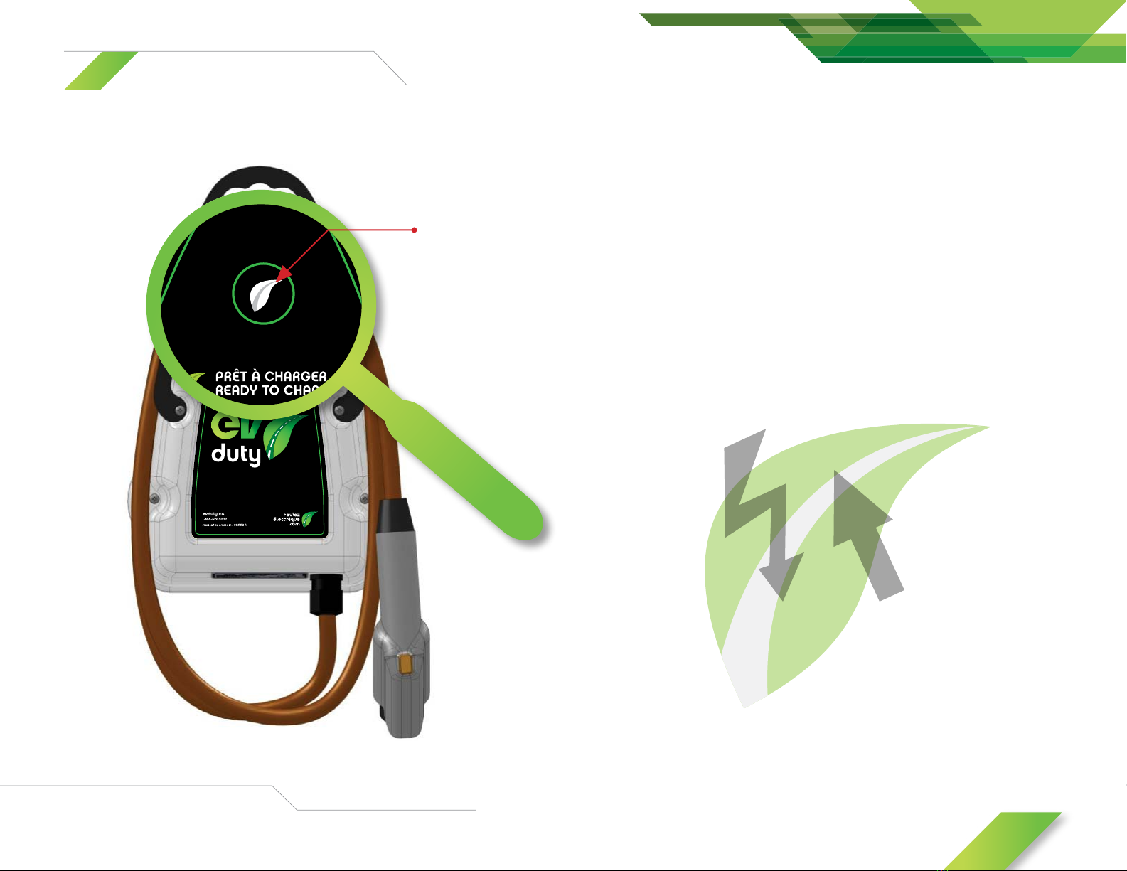
The Main LED on the front of the unit indicates the state of the unit.
This table summarizes the possibilities for the colors of the Main LED.
State of the Main LED
Color Description
Green - Constant The unit is powered up and is ready to accept a vehicle connection.
Yellow - Constant
A vehicle has been detected but it isn’t ready to accept the charge
(This state happens very briey after vehicle connection).
A vehicle has been detected and the charge is completed
(certain vehicles only).
Blue - Constant The vehicle is connected and is in charging state.
Red - Constant
Indoor charging area ventilation required.
No charging allowed.
The unit is in fault mode. Check the troubleshooting table.
Never operate
the unit if the enclosure
isn’t sealed.
11
Figure 8.1.1: Location of Main LED
OPERATING MODES
Instantaneous charging
This is the mode by default. Simply plug the SAE J1772TM connector into
the electric vehicle inlet. The Main LED will turn to BLUE and the charge will
begin for as long as the vehicle stays connected to the Electrical Vehicle
Charging Station.
Main
LED

12
MAINTENANCE AND CLEANING
STORAGE OF THE PORTABLE VERSION
Cleaning
The charging station and the power cords should be cleaned regularly. The
cleaning process can be done using a wet rag.
Do not use water jet, high pressure washer, chemicals agents or
solvents during the cleaning process. Do not splash water on the
power cords or on the plugs/connectors.
Maintenance
This charging station does not require any major maintenance except a
regular verication to be sure that there are no damages or excessive wear
to the charging station itself or to any of the power cords/plugs/connectors.
The portable version of the charging station (models 5 and 31) must be
stored in a clean and dry location, and it must be located away from any
high heat sources.
Avoid oily or corrosive substances from contacting the charging station or
the power cords and plugs/connectors between uses.
Avoid any fall or drop that can lead to impacts between a hard surface and
the charging station. Make sure there is no contact of any sharp object with
the charging station or the power cords or plugs/connectors.
Do not store the charging station in a location where rodents have access,
such as an exterior shed.

13
TROUBLESHOOTING
Troubleshooting Table
Diagnostic Problem Solutions
The Main LED
won’t light up when
powering the unit.
The unit isn’t receiving
a proper power supply.
• Check if the dedicated circuit breaker is at the ON position.
• Check the power supply connections inside
the unit enclosure (Gnd, L1, L2).
The Main LED
is light up
constant red.
The unit is in fault mode.
• Reset the unit by unplugging the NEMA 6-50P plug (Standard version) or
switch the dedicated circuit breaker at OFF and then at the ON position
(Optional version).
• If even after a reset, the unit is still in fault mode,
call the manufacturer support service.
The Main LED
is going from blue
to yellow rapidly.
The Electric Vehicle Charging Cable
is worn, damaged or dirty. • Call the manufacturer support service.
The Main LED
is going from blue
to yellow a few
seconds after
connection to EV.
Power lines L1 or L2 from the main
electrical panel is missing or damaged. • Call the manufacturer support service.
This table lists some of the common
troubles and their possible solutions.

14
ELMEC INC. LIMITED WARRANTY
What does this warranty cover?
This warranty covers any defects or malfunctions of your new EVduty EVC30T Electric Vehicle Charging Station.
How long does the coverage last?
This warranty runs for 3 years from the purchase date.
What will Elmec Inc. do?
Elmec Inc. will repair any EV-Duty EVC30T Electric Vehicle Charging Station judged to have a defect or malfunction as long as the seal on the cover is not broken.
In the event repair is not possible, Elmec Inc. will replace the EVduty EVC30T Electric Vehicle Charging Station with a new one of similar specications and price.
What does this warranty not cover?
This warranty will be void in the case the EV-Duty EVC30T Electric Vehicle Charging Station being opened in any manner so that the internal components are
accessible. The cover is sealed with the rear plate by using rivets and sealant.
How to get service?
To use this warranty, you must contact the Elmec Inc. Support Service, and a qualified technician will verify if there is a real problem with your EVduty EVC30T Electric
Vehicle Charging Station. If it’s the case, send the EVduty EVC30T Electric Vehicle Charging Station postage paid with proof of purchase including serial number to the
following address:
ELMEC INC. SERVICE SUPPORT
1141, 2e avenue, Grand-Mère (Québec) G9T 2X9
Mobile (24/7): 1 819 531-0819 (calls and text messages)
Facebook: Jean-Marc Pittet
Elmec Inc. will inspect the EV-Duty EVC30T Electric Vehicle Charging Station and contact you within 72 hours following the product reception to tell you if the
product will be repaired or replaced.
Your rights under the actual applicable law:
This warranty gives you specific legal rights, and you may also have other rights which vary from one province to another.
15
CONTACT US
Postal address
Elmec Inc. Service Support
1141, 2eavenue
Grand-Mère (Québec)
G9T 2X9
Website
elmec.ca
Email
Service Support
Office
1 819 533-3888
Mobile (24/7)
1 819 531-0819
(calls and text messages)
Fax
1 819 533-3074
WWW.
This manual suits for next models
1
Table of contents
Other Elmec Batteries Charger manuals


