ELMEKO PK 100 User manual

3
INHALTSVERZEICHNIS TABLE OF CONTENTS
Anwendung .................................................................................................................................................................................................4
Technische Daten...................................................................................................................................................................................... 4
Beschreibung .............................................................................................................................................................................................. 5
Leistungsdiagram...................................................................................................................................................................................... 5
Lieferumfang............................................................................................................................................................................................... 6
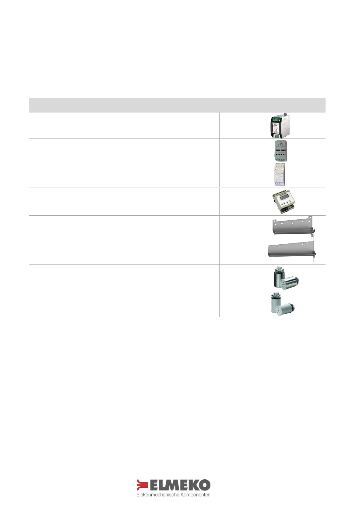
Zubehör......................................................................................................................................................................................................... 6
Montage........................................................................................................................................................................................................ 6
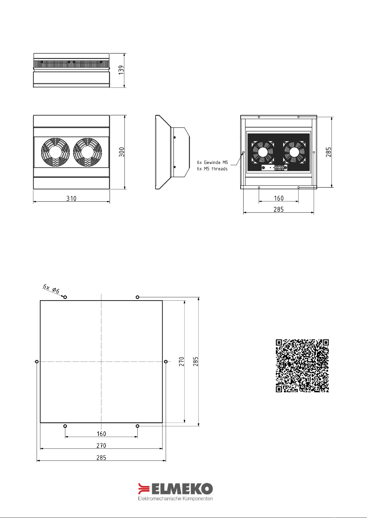
Abmessungen ohne Aufbaugehäuse ................................................................................................................................................ 7
Montageausschnitt ohne Aufbaugehäuse ...................................................................................................................................... 7
Abmessungen mit Aufbaugehäuse.................................................................................................................................................... 8
Montageausschnitt mit Aufbaugehäuse.......................................................................................................................................... 8
Montageablauf ohne Aufbaugehäuse .............................................................................................................................................. 9
Montageablauf mit Aufbaugehäuse................................................................................................................................................10
Elektrischer Anschluss ...........................................................................................................................................................................11
Schaltbild Standard ................................................................................................................................................................................11
Schaltbild sechspolig.............................................................................................................................................................................11
Anschlussbeispiel Kühlen mit TES 60..............................................................................................................................................12
Anschlussbeispiel Heizen und Kühlen mit TRP 205 ..................................................................................................................12
Sicherheitshinweise ................................................................................................................................................................................13
Wartung und Pflege...............................................................................................................................................................................13
Garantieerklärung ...................................................................................................................................................................................14
Application...................................................................................................................................................................................................4
Technical Data ............................................................................................................................................................................................ 4
Discription.................................................................................................................................................................................................... 5
Performance curve.................................................................................................................................................................................... 5
Delivery contents....................................................................................................................................................................................... 6
Accessories .................................................................................................................................................................................................. 6
Installation ................................................................................................................................................................................................... 6
Dimensions without additional housing.......................................................................................................................................... 7
Mounting cutout without additional housing ............................................................................................................................... 7
Dimensions with additional housing ................................................................................................................................................ 8
Mounting cutout with additional housing ...................................................................................................................................... 8
Assembly procedure without additional housing........................................................................................................................ 9
Assembly procedure with additional housing.............................................................................................................................10
Electric installation..................................................................................................................................................................................11
Wiring diagram standard.....................................................................................................................................................................11
Wiring diagram six pole .......................................................................................................................................................................11
Connection example cooling with TES 60.....................................................................................................................................12
Connection example heating and cooling with TRP 205........................................................................................................12
Safety instructions ..................................................................................................................................................................................13
Care and maintenance ..........................................................................................................................................................................13
Guarantee bond.......................................................................................................................................................................................14

4
ANWENDUNG APPLICATION
Die Peltier-Kühlgeräte wurden zur Klimatisierung von Schaltschränken und Wandgehäusen, sowie für Displays
und Großanzeigen entwickelt. Sie zeichnen sich aus durch ihre schnelle und flexible Montage, Zuverlässigkeit,
geringen Wartungsaufwand und ihrer optimalen ästhetischen Integration. Sie sind erhältlich mit einer
Kühlleistung von bis zu 280 Watt. Durch das Edelstahlgehäuse und den vergossenen Lüfter auf der Außenseite
wird ein Outdooreinsatz auch in rauer Umgebung ermöglicht. Die Kühlgeräte erreichen die Schutzart IP67.
Weitere Vorteile sind die Eignung für mobilen Betrieb und die Möglichkeit, die Geräte in jeder Lage zu
montieren, da diese ohne Kältemittel und Vibrationsfrei arbeiten. Der hohe Wirkungsgrad trägt zusätzlich zur
Umweltfreundlichkeit bei. Mit dem passenden Regler ist Kühl- und Heizbetrieb möglich.
The Peltier coolers are developed for cooling of small enclosures and electronic cases, as well as industrial PC
and large displays. They are characterized by their quick and flexible assembly, reliability, low-maintenance and
their optimal aesthetic design. They can be supplied with cooling capacities of up to 280 watts. The stainless-
steel housings and the sealed fan on the outside allows outdoor use even in harsh environments. The coolers
reach degree of protection up to IP67. Further advantages are the suitability for mobile use and the possibility to
install the thermoelectric coolers in every position, because they work without liquid refrigerants and without
vibrations. The high efficiency contributes additionally to the eco-friendliness. With the matching controller
cooling and heating is possible.
TECHNISCHE DATEN TECHNICAL DATA
Bezeichnung Type
PK 100
PK 100 HK**
PK 100 HK + AG
Artikelnummer Part number
40 P10 570
40 P10 57H
40 P10 57HAG
Betriebsspannung
Operating voltage
24 V DC*
24 V DC*
24 V DC*
Eingangs-Spannungsbereich
Input voltage range
18 - 26 V DC
18 - 26 V DC
18 - 26 V DC
Stromaufnahme
Amperage
5,2 A
5,2 A
5,2 A
Anlaufstrom
Starting current
7,5 A
7,5 A
7,5 A
Vorsicherung
Fuse
10 A (T)
10 A (T)
10 A (T)
Kühlleistung bei ∆t= 0 Kelvin
Cooling capacity at ∆t= 0 Kelvin
100 W
100 W
100 W
Heizleistung
Heathing capacity
-
140 W
140 W
Nennleistung
Nominal power
125 W
125 W
125 W
Schalldruck
Sound presure
64 dB(A) @1m
64 dB(A) @1m
64 dB(A) @1m
Luftvolumenstrom
Air volume flow
80 m³/h
80 m³/h
80 m³/h
Schutzart
Degree of protection
IP67
IP67**
IP65
Lebensdauer
Service life
60.000 h
60.000 h
60.000 h
Gewicht
Weight
7200 gr.
7200 gr.
8800 gr.
Einsatztemperatur
Operating temperature
-20 °C … +70 °C
-20 °C … +70 °C
-20 °C … +70 °C
Zulassungen
Approval
UL, CE
UL, CE
UL, CE
* Auch in 12 V DC verfügbar / Also available in 12 V DC **Nema 4X auf Anfrage erhältlich / Nema 4X available on request

5
BESCHREIBUNG DISCRIPTION
Bezeichnung Type
Beschreibung Description
PK 100
Peltier-Kühlgerät Standard (Anschlussklemme vierpolig)
Standard Thermoelectric cooler (terminal four pole)
PK 100 HK
(PK 100-4X)
Peltier-Kühlgerät, Heizen und Kühlen (Anschlussklemme sechspolig)
Thermoelectric cooler, heating and cooling (terminal six pole)
Zulassung Nema 4X optional erhältlich / Approval Nema 4X optionally available
PK 100 HK + AG
Peltier-Kühlgerät, Heizen und Kühlen, mit Aufbaugehäuse (Anschlussklemme sechspolig)
Thermoelectric cooler, heating and cooling with additional housing (terminal six pole)
EIGENSCHAFTEN FEATURES
LEISTUNGSDIAGRAM PERFORMANCE CURVE
Abführbare Verlustleistung / Heat dissipation capacity [W]
Innentemperatur / Inside temperature [°C]
-Thermoelektrische Kühlung ohne Kältemittel
-Einbau in jeder Lage möglich
-Robust gegen widrige
Umgebungsbedingungen
-Hohe Schutzart und robustes Edelstahl-Design
-Platzsparend
-Perfekt für die mobilen Anwendungen geeignet
-Als Option ist Kühlen und Heizen möglich
-Thermoelectric cooling without liquid refrigerant
-Installation possible in any position
-Resistant to adverse environment conditions
-High degree of protection and robust stainless-
steel design
-Compact, small dimensions
-Perfect for mobile applications
-Optional cooling and heating is possible
Mit dem QR-Code haben Sie direkten Zugang zur
umfangreichen Berechnung der benötigten Kühl- und
Heizleistung. Die Berechnungssoftware DELTA T bietet
ihnen dazu eine gute Möglichkeit, Ihr Projekt genau
zu bewerten.
With the QR code you have direct access to the
extensive calculation of the required cooling and
heating capacity. The calculation software DELTA T
offers you a good opportunity to evaluate your
project precisely.

6
LIEFERUMFANG DELIVERY CONTENTS
ZUBEHÖR ACCESSORIES
Bezeichnung
Type
Beschreibung Description
Artikelnummer Part number
Emparro 10
Netzteil Emparro 10
Power supply Emparro 10
42 10A 500
TES 60
Thermostat TES60
Thermostat TES60
15 TES 060
TRP 205
Thermostat TRP 205, Heizen + Kühlen
Thermostat TRP 205, heating + cooling
45 TRP 205
TRP 260
Temperatursteuerung TRP 260
Temperature control TRP 260
45 TRP 260
KRP 200
Kondensatrinne für Peltier-Kühlgerät
Condensate through for thermoelectric coolers
49 KRP 200
KRP 300
Kondensatrinne für Peltier-Kühlgerät
Condensate through for thermoelectric coolers
49 KRP 300
AVDR4SS4
Kondensatablaufstutzen Edelstahl
Condensate vent drain stainless steel
AVDR4SS4
AVDR4NM
Kondensatablaufstutzen Kunststoff
Condensate vent drain plastic
AVDR4NM
MONTAGE INSTALLATION
Für die Montage ist ein Ausschnitt in Türe, Seitenwand, Rückwand oder Dach des Gehäuses erforderlich. Der
Montageausschnitt muss der Montageposition entsprechend sein. Die Montageposition ist so zu wählen, dass
der Luftstrom des Peltier-Kühlgeräts die Temperierung der Komponenten unterstützt. Direktes Anströmen von
temperaturempfindlichen Einbauten mit Kalt- oder Warmluft ist zu vermeiden. Die Lufteintritts- und
Luftaustrittsöffnungen sind freizuhalten. Nur so kann sichergestellt werden, dass die maximale Kühlleistung zur
Verfügung steht. Kühlgeräte können mit und ohne Aufbaugehäuse montiert werden. Für welche
Montagemöglichkeit Sie sich entscheiden, hängt letztlich vom Platzbedarf innerhalb und außerhalb des
Schaltschranks ab und hat keinen Einfluss auf die Kühlleistung.
For installation a cutout is necessary which can be done in door, side, rear or roof of the enclosure. The
mounting cutout must be according to the mounting position. The mounting position should be selected so that
the air flow of the thermoelectric coolers supports the temperature control of the components. Direct oncoming
of temperature-sensitive installations with cold or hot air is to be avoided. The air inlet and air outlet openings
are to be kept unhindered. Only in this way can it be ensured that the maximum cooling power is available.
Thermoelectric coolers can be mounted with or without additional housing. Which mounting option you choose
depends ultimately on the space required inside and outside of the enclosure and has no influence on the
cooling capacity.
-Peltier-Kühlgerät
-Befestigungsschrauben
-Betriebsanleitung
-Thermoelectric cooler
-Fastening screws
-Instruction manual

7
ABMESSUNGEN OHNE AUFBAUGEHÄUSE DIMENSIONS WITHOUT ADDITIONAL HOUSING
MONTAGEAUSSCHNITT OHNE AUFBAUGEHÄUSE
MOUNTING CUTOUT WITHOUT ADDITIONAL HOUSING
Alle Maße in mm All dimensions in mm
Mit dem QR-Code haben Sie direkten Zugang zur
Homepage www.elmeko.de wo der
Montageausschnitt als PDF oder DXF Datei
heruntergeladen werden kann
With the QR code you have direct access to the
homepage www.elmeko.de where the mounting
cut-out can be downloaded as PDF or DXF file

8
ABMESSUNGEN MIT AUFBAUGEHÄUSE DIMENSIONS WITH ADDITIONAL HOUSING
MONTAGEAUSSCHNITT MIT AUFBAUGEHÄUSE
MOUNTING CUTOUT WITH ADDITIONAL HOUSING
Alle Maße in mm All dimensions in mm
Mit dem QR-Code haben Sie direkten Zugang zur
Homepage www.elmeko.de wo der
Montageausschnitt als PDF oder DXF Datei
heruntergeladen werden kann
With the QR code you have direct access to the
homepage www.elmeko.de where the mounting
cut-out can be downloaded as PDF or DXF file

9
MONTAGEABLAUF OHNE AUFBAUGEHÄUSE
ASSEMBLY PROCEDURE WITHOUT ADDITIONAL HOUSING
Montageausschnitt und
Bohrungen nach Zeichnung
anfertigen
Make mounting cutout and
drill holes according to
drawing
Die Schutzfolie der Dichtung entfernen und das Kühlgerät in den Ausschnitt
einsetzen, so dass der Kühlkörper mit Lüfter, Anschlussklemme und
Gewindebolzen in den Schaltschrank hineinragen
Remove the protective film of the sealing and put the cooler into the cutout
so that the heatsink, fans, terminals and the threaded bolts protrude into the
enclosure.
Ansicht von innen: das Kühlgerät
mit sechs selbstsichernden Muttern
M6 mit Unterlegscheiben befestigen
(7 Nm)
View from inside: fasten the cooler
with six self-locking nuts M6 with
washers (7 Nm)
Bei hoher Luftfeuchtigkeit und niedrigen Temperaturen im
Schrankinneren kann sich Kondensatwasser bilden. Abhängig von der
Einbauposition sollte die Kondensatbildung kontrolliert abgeleitet
werden (siehe Kondensatrinne aus dem Zubehör)
At high levels of humidity and low temperatures inside the closure,
condensation water can form. Depending on the installation position,
condensate formation must be drained off in a controlled manner (see
condensate through for accessories)
PK 100 horizontal + KRP 300
PK 100 vertikal + KRP 200
PK 100 vertical + KRP 200

10
MONTAGEABLAUF MIT AUFBAUGEHÄUSE
ASSEMBLY PROCEDURE WITH ADDITIONAL HOUSING
Montageausschnitt und Bohrungen
nach Zeichnung anfertigen
Make mounting cutout and drill
holes according to drawing
Das Kühlgerät auf den Ausschnitt setzen
Place the cooler on the cutout
Ansicht von innen: das Kühlgerät mit
sechs Linsenkopfschrauben M5x16 mit
Unterlegscheibe befestigen (5 Nm)
View from inside: fasten the cooler
with six head screws M5x16 with
washers (5 Nm)
Optimale Kühlung: Die warme Luft wird im Schaltschrank abgesaugt,
im Kühlgerät abgekühlt und dann mit hoher Geschwindigkeit wieder
in den Schrank geleitet. Auf diese Weise wird eine optimale und
gleichmäßige Kühlung im gesamten Schaltschrank erreicht.
Ideal enclosure cooling: Internal enclosure air is sucked up, cooled
inside the cooling unit and blown back with a high speed into the
enclosure. This ensures optimum cooling of the whole panel.

11
ELEKTRISCHER ANSCHLUSS ELECTRIC INSTALLATION
Für den elektrischen Anschluss ist der Schaltschrank vorher vorschriftsmäßig außer Betrieb zu nehmen. Die
Spannungsversorgung ist an die Anschlussklemmen anzuschließen (siehe Schaltbild). Es wird eine
Gleichstromspannung von 24 V DC benötigt. Achtung: Bei Anschluss an Wechselspannung wird das Gerät
zerstört.
For the electrical connection, the control cabinet must first be disconnected. Connect the supply voltage to the
terminals (see wiring diagram). The power supply requires an DC voltage of 24 V DC. ATTENTION: AC current will
destroy the cooler.
SCHALTBILD STANDARD WIRING DIAGRAM STANDARD
SCHALTBILD SECHSPOLIG WIRING DIAGRAM SIX POLE
* Auch in 12 V DC verfügbar / also available in 12 V DC
** Option: über Thermostat geschaltet / switched on with thermostat
Bezeichnung
Term
Belegung Connection
EF
Lüfter Außenkreislauf
External fan
P
Peltier Elemente
Peltier elements
IF
Lüfter Innenkreislauf
Internal fan
Klemmen 1+und 3+ sowie die Klemmen 2- und
4- können auch zusammen angeschlossen
werden
Terminals 1+and 3+ and terminals 2- and 4- can
also be connected together
Bezeichnung
Term
Belegung Connection
EF
Lüfter Außenkreislauf
External fan
P
Peltier Elemente
Peltier elements
IF
Lüfter Innenkreislauf
Internal fan
Klemmen 1+, 3+ und 5+ sowie die Klemmen 2-,
4- und 6- können auch zusammen ange-
schlossen werden
Terminals 1+, 3+ and 5+ and terminals 2-, 4-
and 6- can also be connected together
ACHTUNG!
Bei eingeschalteter Kühlung müssen die Lüfter Außen- und Innenkreislauf immer mit eingeschaltet sein!
ATTENTION!
External and internal fans must run if the cooling is switched on!
Internal fan
1+ 2- 3+ 4-
Peltier elements
External fan
Peltier
elements
External fan Internal fan
1+ 2- 3+ 4- 5+ 6-

12
ANSCHLUSSBEISPIEL KÜHLEN MIT TES 60*
CONNECTION EXAMPLE COOLING WITH TES 60*
ANSCHLUSSBEISPIEL HEIZEN UND KÜHLEN MIT TRP 205*
CONNECTION EXAMPLE HEATING AND COOLING WITH TRP 205*
* Thermostate und Netzteil sind Zubehör und müssen separat bestellt werden
Thermostats and power supply are accessories and must be ordered separately

13
SICHERHEITSHINWEISE SAFETY INSTRUCTIONS
-Die Installation darf nur von autorisiertem Fachpersonal vorgenommen werden. Die landesüblichen
Richtlinien sind gemäß IEC 60364 einzuhalten
-Die technischen Daten auf dem Typenschild und in dieser Anleitung sind zu beachten
-Der Anschluss erfolgt an 24 V DC
-Anschlusskabel sind nur als Kupferleitungen zulässig
-Die maximale Umgebungstemperatur von bis zu 70 °C ist zu berücksichtigen
-Die Umgebung des Geräts darf max. Verschmutzungsgrad 2 entsprechen
-Vorschriften des EVU sind zu beachten
-Bei Beschädigung des Gehäuses oder der Anschlussleitung Spannung abschalten und alle Stecker abziehen
-Achtung! Beim Öffnen des Gerätes erlischt die Garantie
-Schutzmaßnahmen nach VDE 0100 sind sicherzustellen
-Bei der Herstellung von Montageausschnitten und Bohrungen ist geeignete Schutzausrüstung zu tragen
-Luftein- und Luftaustrittsöffnungen des Gerätes dürfen nicht abgedeckt werden
-Stellen Sie vor der Montage sicher, dass der Schaltschrank hermetisch dicht versiegelt ist, ansonsten tritt später
während des Betriebs eine erhöhte Kondensatbildung auf
-Installation must only be carried out by qualified electrical technicians in observation of the respective national
power supply guidelines (IEC 60364)
-The technical specifications on the identification plate and in this manual, must be observed
-Supply voltage is 24 V DC
-Connection cables only as copper conductors only
-Taking into account the maximum surrounding air temperature rating of 70 °C
-The environment of the device may be maximum with pollution degree 2
-If the housing, or wire is damaged, switch off the voltage supply and disconnect all plugs
-Attention! Opening the case will void guarantee
-The safety measures according to VD 0100 have to be ensured
-Wear protective gear when cutting the mounting cut out and drilling the fastening holes
-The air inlet and outlet openings to the unit must not be covered
-Before mounting, make sure that the enclosure is hermetically sealed, otherwise increased condensation will
occur later during operation
WARTUNG UND PFLEGE CARE AND MAINTENANCE
-
Das Peltier-Kühlgerät ist wartungsarm.
-
Führen Sie in regelmäßigen Abständen eine Sichtprüfung an den Lüftern und dem Aussenkühlkörper durch.
-
In staubbelasteter Umgebung kann ein Ausblasen des Kühlkörpers mit Druckluft zur Erhaltung der
Kühlleistung erforderlich sein. Dabei muss das Gerät spannungsfrei geschaltet werden!
-
The thermoelectric cooler is low-maintenance
-
Regularly perform a visual inspection at the fans and the outer heatsink.
-
Dusty environments may require a cleaning of the heatsink with compressed air to maintain the cooling
performance. Before cleaning disconnect the device from the mains!
Die Entsorgung muss gemäß den jeweiligen nationalen gesetzlichen Bestimmungen erfolgen.
The disposal is to occur according to the respective national regulations.
WEEE-Reg.-Nr.: DE 78723147

14
GARANTIEERKLÄRUNG GUARANTEE BOND
Wir gewähren eine Garantiezeit von 24 Monaten ab dem Zeitpunkt der Lieferung des Gerätes bei
bestimmungsgemäßen Einsatz und unter den folgenden Betriebsbedingungen:
-Einsatz in Schaltschränken oder Gehäusen für industrielle Anwendungen
-Beachtung der auf dem Typenschild angegebenen Anschlussspannung und Anschlussleistung
Diese Garantie gilt nicht für evtl. Schäden, die dem Gerät zugefügt werden durch:
-Inbetriebnahme in ungeeigneter Umgebung, z. B. in saurer oder ätzender Atmosphäre
-Anschluss an eine andere Spannung, wie auf dem Typenschild angegeben
-Überspannung, z. B. Blitzeinschlag
-Äußere Gewaltanwendung
Die Garantie entfällt bei einer Benutzung, die nicht den Vorschriften in der Betriebsanleitung entspricht.
Im Schadensfall innerhalb der Garantiezeit übernimmt der Hersteller eine Materialgarantie, indem die
fehlerhaften Bauteile repariert oder ersetzt werden. Der Hersteller übernimmt keinerlei Verantwortung außerhalb
der Reparatur oder dem Austausch defekter Bauteile. Der Hersteller übernimmt keine Aufwendungen für Aus-
und Einbau des Gerätes, oder der Folgeschäden. Die reparierten oder ausgetauschten Bauteile verändern den
Beginn oder die Beendigung der Garantiezeit in keiner Weise.
Es liegt in der Verantwortung des Kunden, die richtige Erdung, Installation und Stromversorgung des Gerätes
entsprechend der gültigen Vorschriften sicherzustellen.
Achtung: Alle Eingriffe in das Gerät haben den Verfall der Gewährleistung und den Haftungsausschluss zur Folge!
We grant a guarantee of 24 months starting from delivery and when the operating instructions are fully
complied with and when they are used in the following conditions:
-Operation in enclosures or cabinets for industrial applications
-Power supply must be same as indicated on the identification plate
This guarantee does not cover any damage to the product due to:
-Using the product in unsuitable environment, e.g. in acid or corrosive atmospheres
-Connection to a supply voltage different from that indicated on the identification plate
-Electrical overload, e.g. through lightning strike
-Damage caused by external force
The guarantee is void with a use, which does not correspond to the regulations in the operating manual.
For each component found to be faulty during the term of the guarantee, the manufacturer will, according to its
unquestionable judgement, repair, and/or substitute the faulty components free of charge. The manufacturer is
in no way held liable except for repairing or substituting faulty products. The manufacturer is not responsible for
any additional expenses incurred for removing, handling and installation if required. The repaired or replaced
products do not change the time the guarantee starts or ends.
It is the customer’s responsibility to see to the correct protective earth connection, installation, and power supply
of the product in compliance with current standards.
Attention: Tampering with the product in any way will void the warranty and exclude any liability!
This manual suits for next models
5
Table of contents
Other ELMEKO Freezer manuals