elokance HA 1600 User manual

USER’S MANUAL
AMPLIFIERS HA-SERIES
HA 1000 . 1600 . 2400 . 3600
Version 1.0
1. Welcome to elokance
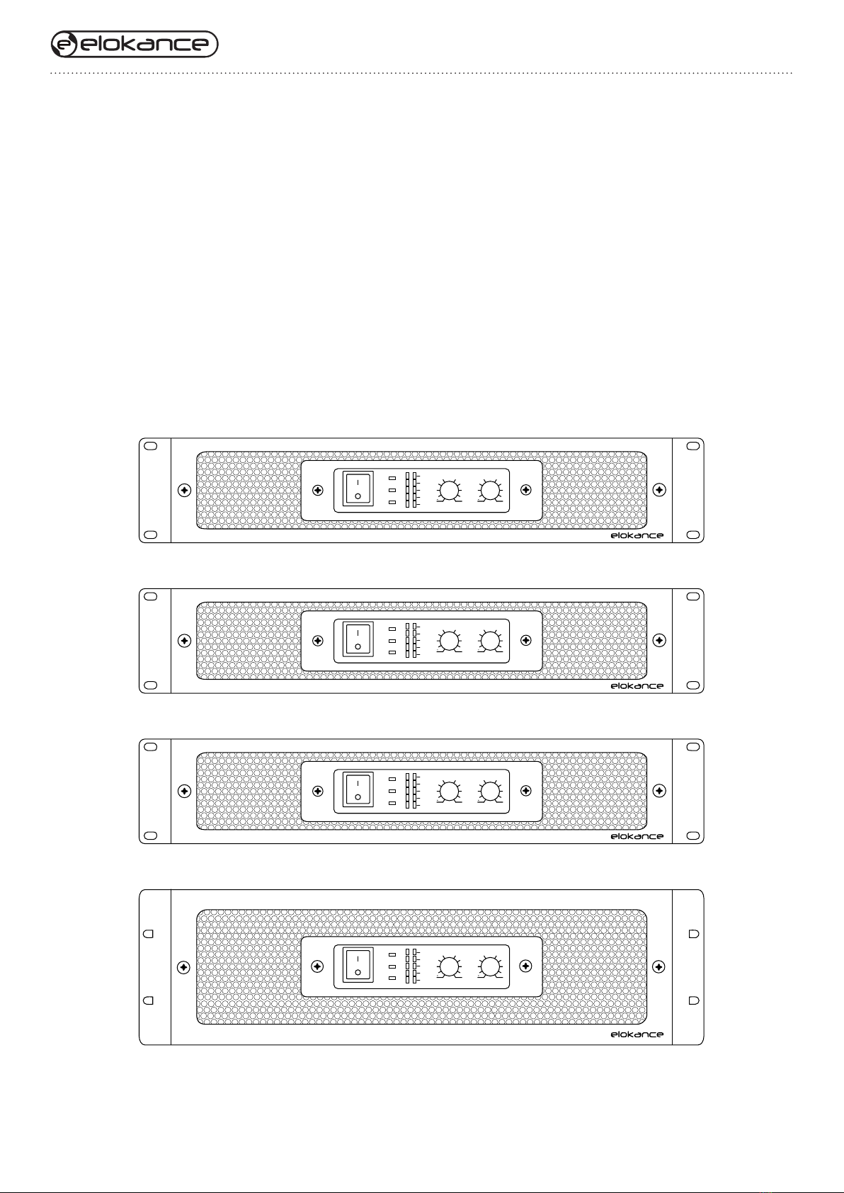
2. Presentation of HA range
3. Important safety precautions
4. Unpacking
5. Installation
6. Specifications
7. Features
Front panel features
Rear panel features
8. System setup examples
9. Troubleshooting
SOMMAIRE
02
02
03
04
05
05
06
07
08
09
Class H Professional Power Amplier
POWER
OFF
CH1
CH1
CH2
POWER
BRIDGE
PARALLEL
SIGNAL
-20db
-10dB
CLIP
PROTECT
ON
HA-3600
CH2
22
32dB
8
22
32dB
8
Class H Professional Power Amplier
POWER
OFF
CH1
CH1
CH2
POWER
BRIDGE
PARALLEL
SIGNAL
-20db
-10dB
CLIP
PROTECT
ON
HA-2400
CH2
22
32dB
8
22
32dB
8
Class H Professional Power Amplier
POWER
OFF
CH1
CH1
CH2
POWER
BRIDGE
PARALLEL
SIGNAL
-20db
-10dB
CLIP
PROTECT
ON
HA-1600
CH2
22
32dB
8
22
32dB
8
Class H Professional Power Amplier
POWER
OFF
CH1
CH1
CH2
POWER
BRIDGE
PARALLEL
SIGNAL
-20db
-10dB
CLIP
PROTECT
ON
HA-1000
CH2
22
32dB
8
22
32dB
8
User’s manual V1.0
02
1. Welcome to elokance
The new HA install amplifier series from elokance is a complete line of high performance installation
amplifiers based on H class technology which operates the output stage to its maximum efficiency all the
time. This HA series provides robust and extraordinarily high fidelity power to drive high power passive
loudspeakers. The HA series are designed, engineered and manufactured with the highest quality standards.
High-pass / Low-pass built-in crossovers, stereo / bridge / parallel modes and an advanced protection
circuitry place this amplifier series to the highest level in pro-audio equipment market.
2. Presentation of HA range
Class H Professional Power Amplier
POWER
OFF
CH1
CH1
CH2
POWER
BRIDGE
PARALLEL
SIGNAL
-20db
-10dB
CLIP
PROTECT
ON
HA-3600
CH2
22
32dB
8
22
32dB
8
Class H Professional Power Amplier
POWER
OFF
CH1
CH1
CH2
POWER
BRIDGE
PARALLEL
SIGNAL
-20db
-10dB
CLIP
PROTECT
ON
HA-2400
CH2
22
32dB
8
22
32dB
8
Class H Professional Power Amplier
POWER
OFF
CH1
CH1
CH2
POWER
BRIDGE
PARALLEL
SIGNAL
-20db
-10dB
CLIP
PROTECT
ON
HA-1600
CH2
22
32dB
8
22
32dB
8
Class H Professional Power Amplier
POWER
OFF
CH1
CH1
CH2
POWER
BRIDGE
PARALLEL
SIGNAL
-20db
-10dB
CLIP
PROTECT
ON
HA-1000
CH2
22
32dB
8
22
32dB
8
Class H Professional Power Amplier
POWER
OFF
CH1
CH1
CH2
POWER
BRIDGE
PARALLEL
SIGNAL
-20db
-10dB
CLIP
PROTECT
ON
HA-3600
CH2
22
32dB
8
22
32dB
8
Class H Professional Power Amplier
POWER
OFF
CH1
CH1
CH2
POWER
BRIDGE
PARALLEL
SIGNAL
-20db
-10dB
CLIP
PROTECT
ON
HA-2400
CH2
22
32dB
8
22
32dB
8
Class H Professional Power Amplier
POWER
OFF
CH1
CH1
CH2
POWER
BRIDGE
PARALLEL
SIGNAL
-20db
-10dB
CLIP
PROTECT
ON
HA-1600
CH2
22
32dB
8
22
32dB
8
Class H Professional Power Amplier
POWER
OFF
CH1
CH1
CH2
POWER
BRIDGE
PARALLEL
SIGNAL
-20db
-10dB
CLIP
PROTECT
ON
HA-1000
CH2
22
32dB
8
22
32dB
8

User’s manual V1.0
03
3. Important safety precautions
Before using your HA amplifier, please read these safety and protection informations regarding your material.
Keep this instruction manual.
Heed all warnings.
Follow all instructions.
WARNING :
To prevent fire or electric shock, do not expose this equipment to rain or moisture. Do not use this apparatus
near water.
Clean only with a dry cloth.
Do not block any ventilation openings. Install in accordance with the manufacturer’s instructions.
Do not install near any heat sources such as radiators, heat registers, stoves, or other apparatus (including
amplifiers) that produce heat.
The appliance coupler is the AC mains disconnect and should remain readily operable after installation.
Do not defeat the safety purpose of the grounding-type plug. A grounding plug has two blades and a grounding
prong. The wide blade or third prong are provided for your safety. If the provided plug does not fit your outlet,
consult an electrician for the replacement of the obsolete outlet. This apparatus should be connected to a receptacle
with a protective earthing (or ground) connection.
Protect the power cord from being walked on or pinched, particularly at plugs, convenience receptacles, and the
point where they exit from the apparatus.
Use only attachments/accessories specified by elokance.
Use only with hardware, brackets, stands, and components sold with the apparatus or by elokance.
Unplug the unit during lightning storms or when unused for long periods of time.
Refer all servicing to qualified service personnel. Servicing is required when the apparatus has been damaged
in any way, such as power supply cord or plug is damaged, liquid has been spilled or objects have fallen into
the apparatus, the apparatus has been exposed to rain or moisture, does not operate normally, or has been
dropped.
User’s manual V1.0
04
3.1. Explanation of Graphical Symbols
The lightning flash with arrowhead symbol within an equilateral triangle is intended to alert the user to the presence
of uninsulated “dangerous voltage” within the product’s enclosure that may be of sufficient magnitude to constitute
a risk of electric shock to persons
The exclamation point within an equilateral triangle is intended to alert the user to the presence of important operating
and maintenance (servicing) instructions in the literature accompanying the product
4. Unpacking
Confirm that the amplifier has no visible shipping damage.
Confirm that amplifier has the correct AC cord and voltage rating for your region.
It is best to keep the carton in case the amplifier needs to be returned, at least until it has been tested.
User’s manual V1.0
05
5. Installation
Only use attachments/accessories specified by the manufacturer.
Be sure to connect to an appropriate outlet with a protective grounding connection. Improper grounding can result
in electrical shock.
Do not allow water to enter this unit or allow the unit to become wet. Fire or electrical shock may result.
Do not place a container with liquid or small metal objects on top of this unit. Liquid or metal objects inside this unit
are a fire and electrical shock hazard.
Do not place heavy objects, including this unit, on top of the power cord. A damaged power cord is a fire and electrical
shock hazard. In particular, be careful not to place heavy objects on a power cord covered by a carpet.
Be sure to connect to an appropriate outlet with a protective grounding connection. Improper grounding can result
in electrical shock
Use of a mobile phone near this unit may induce noise. If noise occurs, move the phone further from the unit.
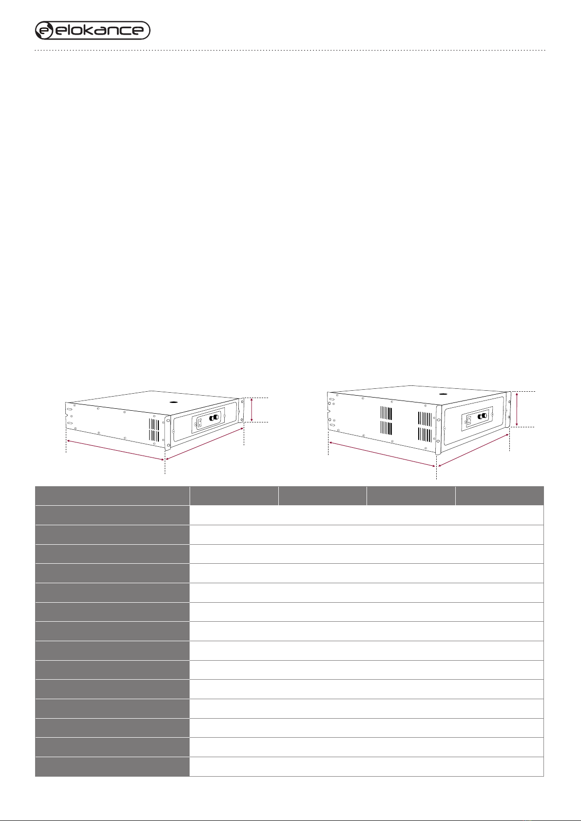
6. Specifications
HA 1000 HA 1600 HA 2400 HA 3600
Type 2 CH Amplifier H-class 2 CH Amplifier H-class 2 CH Amplifier H-class 2 CH Amplifier H-class
Power RMS @8 Ohms 2 x 350 W 2 x 500 W 2 x 800 W 2 x 1200 W
Power RMS @4 Ohms 2 x 500 W 2 x 800 W 2 x 1200 W 2 x 1800 W
Power RMS @2 Ohms 2 x 700 W 2 x 1000 W 2 x 1500 W 2 x 2200 W
Power RMS Bridge @8 Ohms 1000 W 1600 W 2400 W 3600 W
Power RMS Bridge @4 Ohms 1400 W 2000 W 3000 W 4400 W
Frequency Range 20Hz - 20kHz 20Hz - 20kHz 20Hz - 20kHz 20Hz - 20kHz
Damping Factor (1kHz @8 Ohms) > 200 > 300 > 350 > 500
Input CMRR (1kHz) > 60dB > 60dB > 60dB > 60dB
S/N Ration > 102dB > 105dB > 108dB > 112dB
Dimensions 89 x 483 x 380 89 x 483 x 380 89 x 483 x 406 133 x 483 x 444
Net Weight 23kg 26kg 28kg 36kg
Hi-Pass X-over built in 100Hz 100Hz 100Hz 100Hz
Low-Pass X-over built in 100Hz 100Hz 100Hz 100Hz
380
(HA 1000 - 1600)
406
(HA 2400)
380
(HA 1000 - 1600)
406
(HA 2400)
483
89
444 (HA 3600)
483
133

User’s manual V1.0
06
FRONT PANEL FEATURES
1. Power switch and indicator
Press to toggle the power on or off. The POWER indicator lights up green when the power is ON.
2. Bridge mode indicator
The LED will turn on when the amplifier is in Bridge mode.
3. Parallel mode indicator
The LED will turn on when the amplifier is in Parallel mode.
4. Clip indicator
Lights up red when the output signal distortion on the corresponding channel rises above 1% - indicating that “clipping”
has occurred because the signal level is too high.
5. Signal indicator
Lights up green when the corresponding channel’s output level exceeds 2 Vrms (equivalent to 1/2 W into an 8 Ω
load, or 1 W into a 4 Ωload).
6. Volume control knob
Each control knob adjusts the volume of the corresponding channel, from –∞dB to 0 dB.
7. Front panel screws
Unscrew without any tool to clean the dust filter.
7. Features
Power levels matched to the most popular speakers used by entertainers.
Optimized for maximum real-world headroom into 2 Ω, 4Ωand 8Ωspeaker systems.
The unit offers three operating modes :
- STEREO (where Channels A and B operate independently)
- PARALLEL (where the unit outputs a mono source through twin amplifier systems)
- BRIDGE (where the unit operates as a single high-power amp).
Inputs : combo XLR, 1/4” TRS input connectors for compatibility with any source.
Outputs : SpeakON® 2-pole and 4-pole plugs (connects 2 poles only).
Binding posts support all other speaker wiring systems.
Front panel LEDs monitor Power, Signal and Clipping.
Subwoofer / Satellite crossover built-in. High-pass / Low-pass built-in crossovers, stereo / bridge / parallel modes.
7
Class H Professional Power Amplier
POWER
OFF
CH1
CH1
CH2
POWER
BRIDGE
PARALLEL
SIGNAL
-20db
-10dB
CLIP
PROTECT
ON
HA-3600
CH2
22
32dB
8
22
32dB
8
Class H Professional Power Amplier
POWER
OFF
CH1
CH1
CH2
POWER
BRIDGE
PARALLEL
SIGNAL
-20db
-10dB
CLIP
PROTECT
ON
HA-2400
CH2
22
32dB
8
22
32dB
8
Class H Professional Power Amplier
POWER
OFF
CH1
CH1
CH2
POWER
BRIDGE
PARALLEL
SIGNAL
-20db
-10dB
CLIP
PROTECT
ON
HA-1600
CH2
22
32dB
8
22
32dB
8
Class H Professional Power Amplier
POWER
OFF
CH1
CH1
CH2
POWER
BRIDGE
PARALLEL
SIGNAL
-20db
-10dB
CLIP
PROTECT
ON
CH2
22
32dB
8
22
32dB
8
1 2
3 5 6
4

User’s manual V1.0
07
REAR PANEL FEATURES
1. Signal input connections
Connect with Balanced / Unbalanced ¼-INCH or male XLR.
2. Ground / Lift selector
1 is Lift, 3 is Ground.
3. LF filter
Position 1 = cut all frequencies below 50Hz
Position 2 = cut all frequencies below 30Hz
Position 3 = no filter (full range).
4. Crossover
Position 1 = cut all frequencies below 100 Hz
Position 2 = cut all frequencies above 100 Hz
Position 3 = no filter (full range).
5. Output modes
Position 1 = Parallel mode
Position 2 = Bridge mode
Position 3 = Stereo mode.
6. Link output
Direct output of input signal (THRU).
7. Binding post output
Bare wires or terminals may be inserted into the side holes. Red for + and Black for -. For the bridge mode, connect
both RED pins to the speaker.
8. SpeakON output (Neutrik)
Insert and turn until the connector clicks. Use the thumb latch or locking ring to release the plug.
9. AC power connector (Neutrik)
Connect your Powercon cable.
10. Fuse
T10AL ~250V (HA 1000)
T12AL ~250V (HA 1600)
T15AL ~250V (HA 2400)
T25AL ~250V (HA 3600)
INPUT PINOUTS
1/4 XLR
P2
P3
P1
BALANCE
SIGNAL+ SIGNAL+
SIGNAL-
SCREEN SCREEN
SCREEN
UNBALANCE
TIP
RNG
SLV
INPUT IMPEDANCE:
20K BALANCED
10K UNBALANCED
LIFT/
GROUND
LIFT1
2
3GROUND OFF OFF STEREO
BRIDGE100HZ HF30HZ
100HZ LF PARALLEL
50HZ
LF
FILTER
HF/LF
FILTER
OUTPUT
MODE
CAUTION
RISE OF ELECTRIC SHOCK
DO NOT OPEN
CAUTION:PREVENT ELECTRIC SHOCK DO NOT REMOVE
WARNING:TO REDUCE THE RISK OF FIRE OR ELECTRIC
TOP OR BOTTOM COVERS. NO USER SERVICEABLE PARTS INSIDE
SHOCK. DO NOT EXPOSE THIS EQUIPMENT TO RAIN OR MOISTURE
Made in P.R.C
T10AL 250V
230V/50Hz
CH2
BRIDGE
CH1
1+
1+ 2+
2+ 2-
POS NEG
NEG
NEG
POS
POS
1-
CH2
1+
POS NEG
1-
LIFT
GROUND
1 1 1
2 2 2
3 3 3
FILTER FILTER MODE
LF HF/LF OUTPUT
INPUT PINOUTS
1/4 XLR
P2
P3
P1
BALANCE
SIGNAL+ SIGNAL+
SIGNAL-
SCREEN SCREEN
SCREEN
UNBALANCE
TIP
RNG
SLV
INPUT IMPEDANCE:
20K BALANCED
10K UNBALANCED
LIFT/
GROUND
LIFT1
2
3GROUND OFF OFF STEREO
BRIDGE100HZ HF30HZ
100HZ LF PARALLEL
50HZ
LF
FILTER
HF/LF
FILTER
OUTPUT
MODE
CAUTION
RISK OF ELECTRIC SHOCK
DO NOT OPEN
CAUTION:TO PREVENT ELECTRIC SHOCK DO NOT REMOVE
WARNING:TO REDUCE THE RISK OF FIRE OR ELECTRIC
TOP OR BOTTOM COVERS. NO USER SERVICEABLE PARTS INSIDE
SHOCK. DO NOT EXPOSE THIS EQUIPMENT TO RAIN OR MOISTURE
Made in P.R.C
T25AL 250V
230V/50Hz
CH2 BRIDGE
CH1
1+ 1+ 2+
2+ 2-
NEG NEG NEG
POS POS POS
1-
CH2
1+
POS NEG
1-
LIFT
GROUND
1 1 1
2 2 2
3 3 3
FILTER FILTER MODE
LF HF/LF OUTPUT
1 6 8 107 92 3 4 5

User’s manual V1.0
08
8. System setup examples

User’s manual V1.0
09

User’s manual V1.0
10
9. Troubleshooting
NO POWER, NO LIGHTS, NO FAN
Confirm that the AC cord is fully seated and connected to a live outlet. Check the AC source by trying another device
such as a lamp. Check the FUSE on the back of the amplifier.
INTERFERENCE FROM CELL PHONES
Using a cell phone near the speaker system can induce noise. If this occurs, move the cell phone further away from
the speaker system.
BOTH CHANNELS PRODUCES DEEP BASS ONLY
Check the position of the CROSSOVER switch on the rear panel. Set the HF/LF switch to position 3 (full range).
AMPLIFIER SOUNDS DISTORTED
If the red CLIP LED is flashing, the amplifier is being played beyond its normal rated power. The circuitry will reduce
volume somewhat to prevent severe overdrive, but if the input signal is further increased, the limiter can be overrid-
den, with increased distortion.
If the speakers or speaker cables are shorted or defective, the amplifier may distort at lower-than-normal levels, with
increased flashing of the red CLIP LED. This should be checked by trying an alternate speaker and cable. If too
many speakers are connected to each channel (impedance below 2 ohms), the amp will overload more easily and
will probably run hot.
If the sound is distorted or garbled without flashing the red CLIP LED, the distortion is not occurring inside the ampli-
fier. Either the speaker is bad or the input signal is distorted.
Confirm that the speaker is OK by trying a different unit.
Input overload can occur if the amplifier Gain controls are set too low, and the input source is overdriven to compen-
sate Reduce the source volume until the distortion clears up, and increase amp Gain to reach the desired level. It is
generally desirable to keep the amp gains at or near their full, clockwise, position.
Check all input connections. Do not plug two different sources into the same channel. Use a mixer to blend sources.
NO SOUND, NO GREEN OR RED LED
Confirm that the Gain controls are turned up.
Confirm that the input cables are correctly installed at both ends. If using 1/4-inch speaker cables, do not confuse
with input cables.
Confirm that the source is active. If necessary, try another source, or connect another amplifier to the existing source.

User’s manual V1.0
11
NO SOUND, BUT THE GREEN LED IS RESPONDING
The green LED indicates the amp is producing a signal, so sound should be heard if the speaker is connected.
Check the speaker connections at both ends, and try a different speaker.
NO SOUND, RED LED ON
The amp mutes briefly when turned on and off to prevent thumps. If the amp overheats severely, it will mute until it
cools off. The fan will be running at full speed, and sound should resume in less than a minute. If the amp feels hot
and the fan is not running, it needs to be serviced.
BACKGROUND HUM
Balanced XLR or TRS cables are better for long runs.
AMPLIFIER NEEDS SERVICING
The following conditions indicate possible unsafe conditions that require service before using.
If observed, unplug the AC cord from the wall and when safe, remove the amp for servicing.
If the amplifier emits smoke or burning smells.
If the case is severely dented or deformed.
If the amplifier is soaked with any fluid.
If internal parts sound loose.
If the AC breaker trips when power is applied.
If the amplifier is dropped, carefully inspect for damage or loose parts before attempting to use.

www.elokance.com
This manual suits for next models
4
Table of contents


