5310923-06/02UK
Technical Manual TAR 1310 / 2310 / 4310 Page 5
Parameters
Defaultvaluesandsettingsarefactory
settings.
Values marked 'X' are for information
only and can not be edited.
Note:
It is possible to reset all
parameters to default:
Switch off supply voltage,
press and hold the 'P'-key,
Switch on supply voltage.
Installation
Before applying voltage to the
controller make sure that all wi-
ring has been made in accor-
dance with the wiring diagram in this manual
and is fitting the application.
Sensor leads may be up to some hundred
meters, but should be shielded cable with one
end of the shield connected to ground. This
avoids irregular switching caused by electro-
magnetic interference.
Applications with Free-Air Defrost
When this defrost method is used, there is no
need for having a defrost sensor at the evapo-
rator.In thiscasethe sensormust be simulated
by a fixed resistor (1.3 kOhms).
The controller then terminates a defrost cycle
only by time which is set with parameter P17.
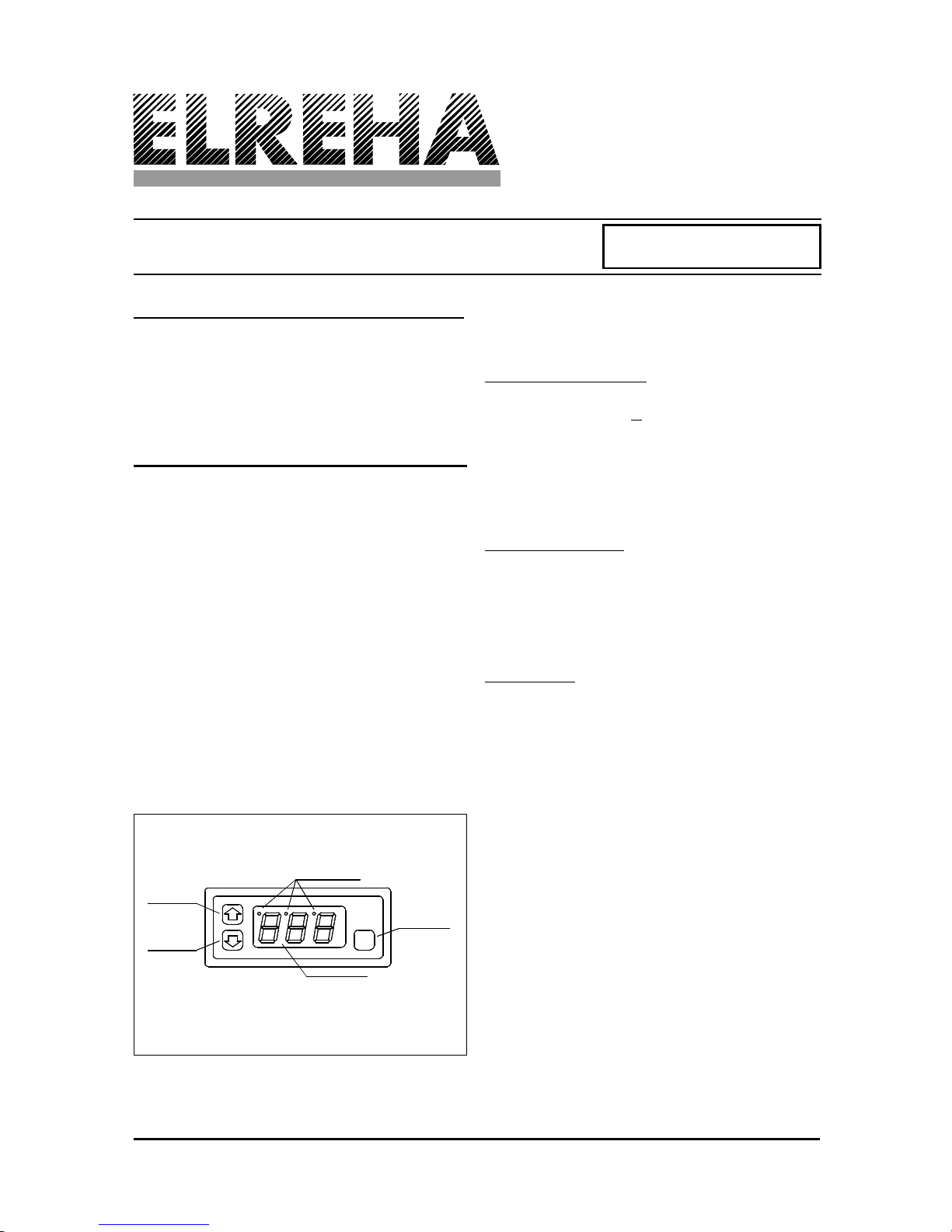
Getting Started
Upon applying voltage to the controller, the
display reads the temperature of the control
(room) sensor. After you have punched in the
access code (see chapter "unlock keys"), you
programm the configuration of the controller to
suit your application:
switching mode: parameter P07,
display mode: P08,
defrost method: P12
evaporator fan mode: P20,
and/or the alarm mode: P25
Thebasicsetupiscompletenow
and you can edit the setpoints,
delay times etc.
Iffor any reason theactualsen-
sorvaluesdisplayedshouldnot
matchwiththetemperatureyou
read from a high accuracy ther-
mometer, you can correct the error with para-
meter P09/P10.
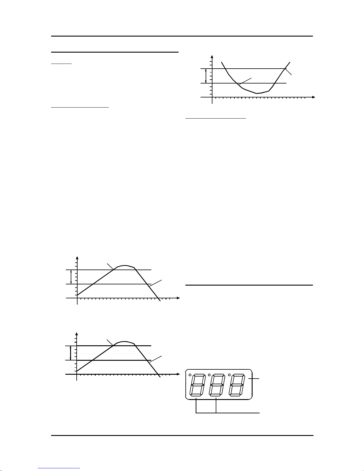
Failure Mode
In case of sensor failure (short circuit or interrupt)
the display starts flashing and the controller inter-
rupts all functions. If there is a control sensor
failure,thewarningrelaycomesonafterthewarning
time delay is over.
Technical Data
Supply Voltage
TAR 131x ................................ 12 V AC/DC
TAR 231x ................................ 230 V AC
TAR 431x ................................ 230 V AC
Consumption ............................... apr. 3.5 VA
Contact Rating ............................ 8 A resistive
3 A inductive
Temperature range
working.................................... -10....+55 °C
storage .................................... -30....+70 °C
data storage ................................ unlimited
real time clock ............................. power backup
for 10 days
Display ........................................ LED red 1/2"
Relay Position Indicator .............. 1.2 mm red
Buzzer ......................................... 3.5 kHz inter-
mittent
84 dB/30cm
Screw terminals .......................... 2.5 mm
Protection
TAR 131x ................................ IP 54 front
TAR 431x ................................ IP 54
TAR 231x ................................ IP 30