Elseta IOMOD 4RTD User manual

IOMOD 4RTD is used for temperature data monitoring over Modbus or IEC-60870-103 using resistance temperature
detector (RTD) platinum sensors. Up to 4 RTD temperature sensors can be connected at once.
● Temperature sense with ±0.5 °C accuracy over all operating conditions;
● Selectable PT100 ar PT1000 RTD temperature sensor for every channel (2, 3 or 4 wire);
● 2.5kV(rms) isolated RTD inputs;
● Configurable temperature and sensors’ fault detection for every channel;
● Temperature sensing range from -200 up to 800 °C when using platinum RTD sensors;
● Configurable Modbus or IEC-60870-103 settings: Slave ID, baud rate, parity and stop bits, RS485 terminating
resistor, etc.
● Firmware upgrade over USB.
IOMOD uses Modbus (RTU) or IEC-60870-103 protocols over RS485 connection, which can be used for cable lengths up
to 1500 meters and connect up to 30 devices on one line. Default Modbus and IEC-60870-103 settings are: 9600
bauds/s baudrate, 8N1, Slave (Link) address - 1.
To read temperature using Modbus (RTU) protocol user can use device with default settings without configuring it. To
read temperature from RTD sensor, send 04 Modbus command (Read Input Registers) with resolution of two registers
from 0 to 7. Odd numbers represent least significant words, even numbers represent most significant words. For
example, to read temperature measured by first RTD, read register 0 and 1, where register 0 is least significant word.
Two words read by Modbus represent a float type (IEEE-754 compatible) variable.
For further information regarding setting temperature parameters and configurable options please refer to table shown
below, also supported MODBUS functions described in paragraphs described below.
CONFIGURABLE OPTIONS
OVER USB
OVER MODBUS
Slave Address
Yes
No
Baudrate
Yes
No
Data, Stop and Parity bits
Yes
No
RS485 Terminating Resistor
Yes
No
RTD parameters
Yes
No
Default settings
Yes
No
Setting temperature limits
Yes
Yes
Fault configuration
Yes
Yes
Status LED can be in 2 colors :
Blue - Device connected to USB.
Green - Normal operation.
The RX/TX LED on the IOMod flashes when data is either being transmitted or received via the RS485 port.
IOMOD 4RTD User Manual Modbus
Introduction
Features
Operational Information
Status LED
Rx/Tx LED

01 (0x01) Read Coil Status
Used to read fault flags. Fault is implemented as high logic level if any configured fault has occurred, zero otherwise.
Fault flags are cleared automatically if possible.
03 (0x03) Read Holding Registers
May be used to read holding registers containing temperature limits defined by user in degrees Celsius, fault mask
register.
Temperature limits are defined as 16-bit integer values. Values that are below or above the predefined limits are
ignored. These limits are described in Modbus register mapping table below. If upper limit value is lower than lower
limit value, these values are switched between them.
Fault mask registers contain information about fault bits that would be lifted in fault register if any particular fault for
particular RTD has occurred. Its values for every four RTDs are kept at holding register of addresses 11 to 14.
04 (0x04) Read Input Registers
May be used to read current temperature values and faults.
As temperature is kept as a 4-byte wide float value, two neighboring register are used to keep it. RTD values are kept
at registers 0 to 7, least significant word first. Values read can be easily converted using any converter capable of
converting floats based of IEEE-754 standard.
Fault register values are read as 16-bit input registers on addresses 16 to 19. Meanings of individual bits are explained
below, in subsection Fault registers.
06 (0x06) Preset Single Register
Used to set holding registers one by one described when explaining 03 Modbus function. That means that arbitrary
value may be written to set up different temperature limits and faults masks.
Register (decimal)
Description
Value range
Read coil status (01)
00010-00013
Reading fault flags
0-1
Read holding register (03)
00000-00007
Get temperature limits (lower limit first)
-200-800
00011-00014
Fault Mask registers for RTDs
0-57836
Read input registers (04)
00000-00007
Temperatures from RTD sensors, LSW first
0-65535
00016-00019
Fault registers for RTD sensors
0-57836
Preset Single Register (06)
00000-00007
Set temperature limits (lower limit first)*
-200-800
00011-00014
Set Fault Mask register for RTDs
0-65535
Fault registers (Modbus addresses - 16-19) are read-only. They represent faults that occurred during operation of
device. To enable showing desired fault user should set appropriate bits in Fault mask register (Modbus addresses - 11-
14) or via USB interface, entering Advanced Settings Tab in RTD parameters menu. Fault registers and fault masked
registers are different for different temperature channels. Default values are shown in brackets below.
Fault register[15:14] shows flags that are lifted if temperature limits are exceeded. Bits[7:5,3:2] inform about faults
that were detected by RTD reading chip. These faults are usually lifted if unsuitable settings are set or RTD is faulty or
not connected.
Supported MODBUS functions
Modbus register table
Fault registers

Fault register
15
(R-0)
14
(R-0)
13
(R-0)
12
(R-0)
11
(R-0)
10
(R-0)
9
(R-0)
8
(R-0)
RTD
Temperature
Hi Threshold
RTD
Temperature
Lo Threshold
-
-
-
-
-
-
7
(R-0)
6
(R-0)
5
(R-0)
4
(R-0)
3
(R-0)
2
(R-0)
1
(R-0)
0
(R-0)
RTD Code Hi
Threshold
RTD Code Lo
Threshold
RTD REFIN- >
0.85 x VBIAS
-
RTD FORCE
Open
RTD
Overvoltage/
Undervoltage
-
-
Fault mask register
15
(R/W-0)
14
(R/W-0)
13
(R/W-0)
12
(R/W-0)
11
(R/W-0)
10
(R/W-0)
9
(R/W-0)
8
(R/W-
RTD
Temperature Hi
Threshold Fault
Enable
RTD
Temperature Lo
Threshold Fault
Enable
-
-
-
-
-
-
7
(R/W-1)
6
(R/W-1)
5
(R/W-1)
4
(R/W-0)
3 (R/W-1)
(R/W2 -1)
1 (R/W 0) -
0 (R/W 0)
RTD Code Hi
Threshold
RTD Code Lo
Threshold
RTD REFIN-
> 0.85 x
VBIAS Fault
-
RTD FORCE
Open
RTD
Overvoltage/Un
dervoltage
-
-
System
Dimensions
17.5 (H) x 101 (W) x 119 (L), mm
Case
ABS, black
Working environment
Indoor
Working temperature
-40 | +80°C
Recommended operating
conditions
5 – 60°C and 20 – 80% RH;
Configuration
USB
Firmware upgrade
USB – mass storage device
Electrical characteristics
Technical information

Termination resistor
Selectable, 120Ω
Power
Power Supply
9-33 VDC
Current consumption
40mA @ 12VDC, 20mA @ 24VDC
IOmod 4RTD can be powered through main power connector +12/24 VDC or through USB. Apply +12/24VDC to V+
and 0 V to V-. The device has a built-in reverse voltage polarity, overcurrent and overvoltage protection.
IOMod 4RTD has one RS485 connector. Connect RS485 cable pair to contacts marked RS485/A and RS485/B.
Connections should be made with minimum possible cable stub.
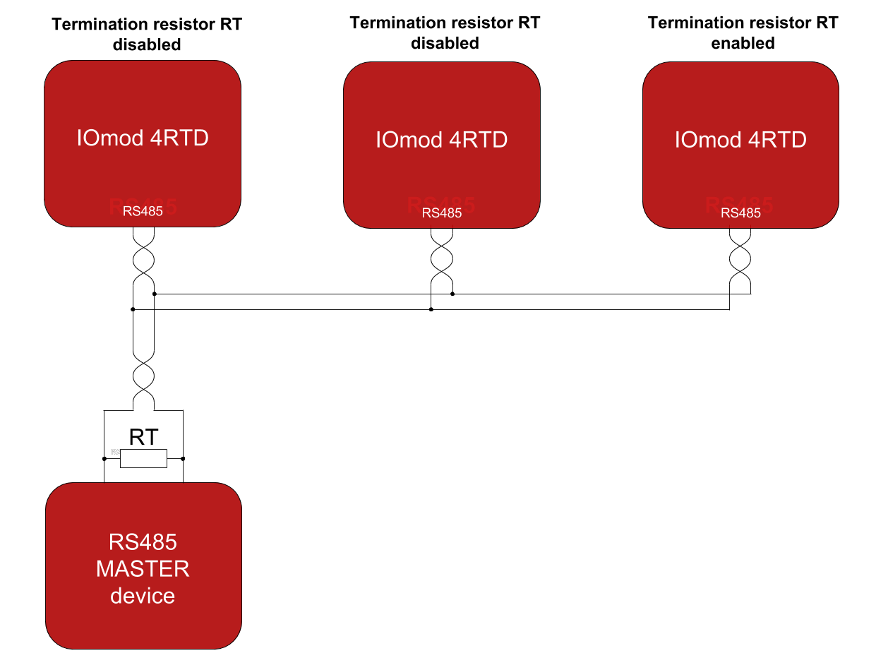
IOMOD 4RTD has integrated 120Ω termination resistor which can be enabled or disabled over USB configuration. It is
recommended to use termination at each end of the RS485 cable. See typical connection diagram on Fig. 5.1.
Fig. 5.1. Typical IOMod connection diagram
IOMOD 4RTD has 1/8 Unit load receiver which allows to have up to 256 units on line (compared to standard 32 units).
To reduce reflections, keep the stubs (cable distance from main RS485 bus line) as short as possible when connecting
device.
IOMOD 4RTD devices has indications that help user easily debug possible problems. Light emitting diodes can show if
RTD fault has happened on any of four RTD measuring channels (FLT1-FLT4). STAT LED indicates if proper power
Device Connection
Power connection
RS485 serial interface
Status indication

connection is made - this LED is always on if device has a power connection. Blue light means device is only powered
via USB, green light indicates proper power connection is made and there is no fault condition on printed circuit board
, red light indicates there is something wrong with either power connection or RTD channels. RX/TX status LED
indicates if RS- 485 transmission is happening at a moment.
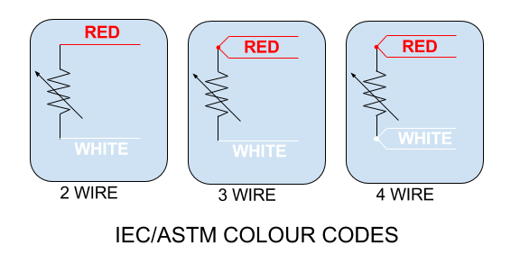
Fig. 5.3. RTD sensor colour codes
IOmod 4RTD accepts 2-wire, 3-wire or 4-wire connection types of RTD sensors (PT100, PT1000). Firstly, select a sensor
type (PT100 or PT1000) using a USB terminal. Secondly, use the following instructions depending on the number of
wires of a selected RTD sensor.
2-wire RTD sensor: connect red wire to RTD+ and white wire (or black) to RTD- contacts. The connection between
RTD+ and F+, RTD- and F- must be shorted.
3-wire RTD sensor: connect one red wire to RTD+, second red wire (compensating lead wire) to F+ and white (or black)
wire to RTD-. The jumper between RTD- and F- must be shorted.
4-wire RTD sensor: connect red wires to RTD+ and F+ contacts, white (or black) wires to RTD- and F- contacts. No
contacts shall be shorted.
IOmod 4RTD USB interface is used for configuration, diagnostics and firmware updates. IOmod 4RTD is powered
through USB when connected, no extra power connection needed for operation. Use a USB mini B cable for connection.
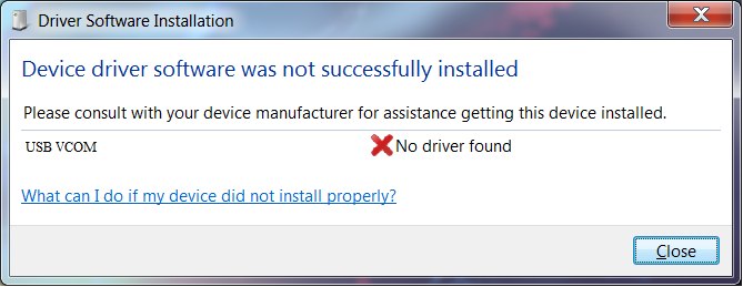
Device requires USB drivers to work as a Virtual COM port. First-time connection between device and computer could
result in “Device driver software was not successfully installed” error such as one shown in Fig.6.1.
Fig. 6.1. Unsuccessful device software installation error
A user then should manually install drivers by selecting a downloaded driver folder:
RTD sensor connection
USB interface
Configuration over USB
Driver installation

Go to Control Panel -> Device Manager;
Select a failing device;
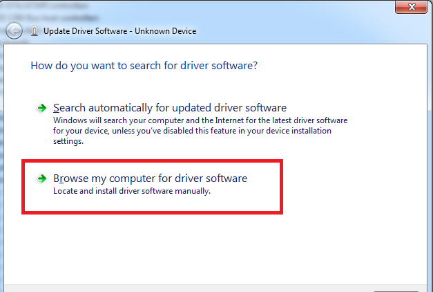
Press “Update driver software”; screen as in Fig. 6.2. should appear:
Fig. 6.2. Device driver software update message
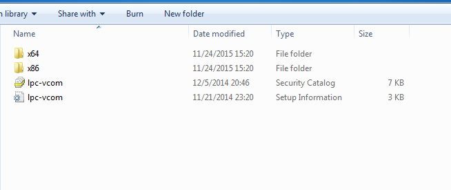
Select “x86” driver for a 32-bit machine or x64 for a 64-bit machine. If not sure, select a root
folder (folder in which x64 and x86 lay inside, as in Fig. 6.3).
Fig. 6.3. Device driver folder content
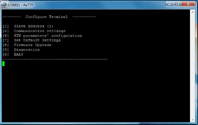
Configuration of IOMOD device is done through CLI (Command Line Interface) on virtual COM port. Drivers needed for
MS Windows to install VCOM will be provided. To open up CLI simply connect to specific VCOM port with terminal
software (it is advised to use PuTTY terminal software. If other software is being used, user might need to send
<return> symbol after each command). When connected user should immediately see main screen similar to one in
Fig.6.4.
IOMod 4RTD configuration via PuTTY terminal

Fig. 6.4. The main menu for IOMod 4RTD
Navigation is performed by pressing number connected to its function. User then should proceed by following further
on-screen instructions. For example, to set desired slave address, press [1] to enter Slave Address screen; enter new
configuration; press [RETURN] to save, or [ESC] to cancel changes. When done, press [0] (exit) before disconnecting
device. Default values are set by pressing [7] on main screen, and later confirming these changes by pressing [1].
If terminal window is accidentally closed without exiting, user can connect to terminal again, and press any key on
keyboard to show up main menu once again.
Configuration of device is not possible when USB Simulation Mode is entered. To access configuration menu again user
should reset device and then try again.
Modbus Main menu
Menu Name
Function
Values
Default Values
1.
Slave Address
Modbus Slave address / ID
1-247
1
2.
Communication settings
[1] Baud rate,
[2] Data, Stop and
Parity Bits,
[3] RS485
Terminating resistor
[1] 100 - 256000,
[2] 8 Data bits + 1/2
Stop bits,
Even/None/Odd
Parity
[3] Enabled/Disabled
[1] 9600,
[2] 8N1,
[3] Enabled
6.
RTD parameters’
configuration*
Configuring Callendar-Van
Dusen coefficients,RTD
wire count, type, etc.
PT100, 2 wires, coefficients
according to IEC-751
7.
Set Default Settings
Sets Default Settings
(1 to confirm, 0 to cancel)
-
8.
Firmware Upgrade
Mass Storage Device
Firmware Upgrade
(1 to confirm, 0 to cancel)
-
9.
Diagnostics
Input / Output states
-
-
0.
Exit
Exit and disconnect
-
-
To update device firmware user must enter main configuration menu.
Enter Firmware update screen by pressing [8];
Confirm update by pressing [1];
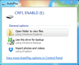
Device now enters Firmware Upgrade mode. Device reconnects as mass storage device (Fig 6.10.).
It is recommended to close terminal window after entering firmware upgrade mode.
Firmware upgrade over USB

Fig. 6.10. Mass storage device warning
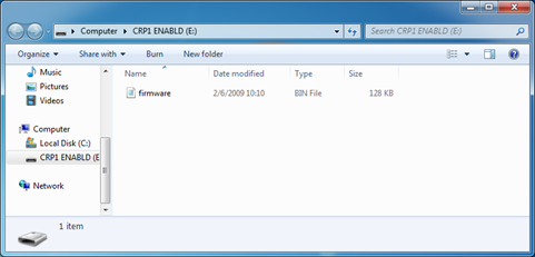
User then must delete existing file “firmware.bin”, and simply upload new firmware file by drag and drop. (Fig 6.11.)
Fig. 6.11. Dragging and dropping new firmware file
Reconnect device and check firmware version. It should now represent the one it was updated to.
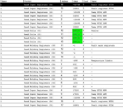
To test IOMOD 4RTD with default settings, user can connect device through RS485 to Modbus or IEC-60870 (depending
on firmware) master or using USB Simulation Mode. Example will show The Vinci Expert as serial interface converter
and adapter to PC with The Vinci software. Default settings – 9600 baud; 8 data, no parity, 1 stop bit. When opening
The Vinci software, choose Modbus serial – Master mode. In Settings tab, choose station number (default – 1);
configure tags (as described in section 2. Device operational information); press Start and go to Statistic tab:
Fig. 6.7. Example of results of Modbus testing
Testing With “THE VINCI” software

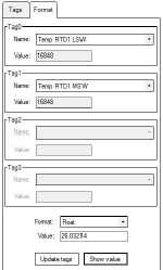
Fig.6.8. Representing temperature as float when using Modbus
Fig. 6.8. represents how The Vinci software should be configured to represent temperature in IEEE- 754 standard float
type when using Modbus communication.
Revision #4
Created 1 December 2021 13:47:53 by Tautvilis
Updated 3 May 2022 08:26:01 by Simas
Table of contents
Popular Measuring Instrument manuals by other brands

PCB Piezotronics
PCB Piezotronics Triaxial ICP 339A31/NC Installation and operating manual

Endress+Hauser
Endress+Hauser CleanFit P CPA 471 operating instructions

Kusam-meco
Kusam-meco CA-1000 manual

GHM
GHM GREISINGER GIA 20 EB Mounting and operating manual

Elvaco
Elvaco CMi4110 user manual

EUTECH INSTRUMENTS
EUTECH INSTRUMENTS ECOSCAN CON TDS 5 CONDUCTIVITY PORTABLE... Mode d'emploi


