STAUFF PPC-06 User manual

Stauff Hydraulic Tester
PPC-06/08/12
Operating instructions
Version 2.1
Artikel-Code: 1810000112
2007-08-24

Operating Instructions Hydraulic Tester PPC-06/08/12
2
Walter Stauffenberg GmbH & Co. KG
Im Ehrenfeld 4 D-58791 Werdohl
Postfach 1745 D-58777 Werdohl
Germany
Telefon: +49 (0) 2392 / 916 – 0
Telefax: +49 (0) 2392 / 2505
E-Mail: [email protected]
Internet: www.stauff.com

Operating Instructions Hydraulic Tester PPC-06/08/12
3
Directory
1Unpacking.....................................................................................................................................5
1.1 Protection of PPC-06/08/12 ...................................................................................................5
2General remarks ..........................................................................................................................6
2.1 Instrument types.....................................................................................................................6
3Functions and settings ...............................................................................................................7
3.1 Operating the PPC-06/08/12..................................................................................................9
3.1.1 Switching on the PPC ............................................................................................................9
3.1.2 Display..................................................................................................................................10
3.1.3 Connection of sensors .........................................................................................................11
3.1.4 Operation and display control ..............................................................................................12
3.1.5 Number input........................................................................................................................14
3.1.6 Text input .............................................................................................................................16
3.2 Measurement and display....................................................................................................18
3.2.1 Display of measured values (ACT – MIN - MAX) ................................................................18
3.2.2 Deleting MIN / MAX memory ...............................................................................................21
3.2.3 Temperature.........................................................................................................................21
3.2.4 Differential values.................................................................................................................22
3.2.5 Alignment of I1 and I2 ..........................................................................................................23
3.2.6 Optional channel (combination) ...........................................................................................24
3.3 Data output...........................................................................................................................28
3.3.1 Online function .....................................................................................................................29
3.3.2 Online function with PC / Laptop..........................................................................................30
4Auxiliary sensors / current - voltage measurement ...............................................................34
4.1 Configuration of auxiliary sensors........................................................................................35
4.2 Frequency measurement .....................................................................................................37
5Additional features of the PPC-06/08/12..................................................................................39
5.1 Memory capability ................................................................................................................41
5.2 Manual recording of measured values.................................................................................43
5.3 Software-driven recording of measured values ...................................................................45
5.3.1 Edge-triggered recording .....................................................................................................46
5.3.2 Externally triggered recording ..............................................................................................50
5.3.3 Manually triggered recording ...............................................................................................54
5.3.4 Time triggered recording......................................................................................................58
5.4 Memory output .....................................................................................................................62
6Configuration PPC-06/08/12......................................................................................................65
6.1 Device Setup........................................................................................................................66
6.1.1 RS 232 interface test............................................................................................................67
6.2 Battery Service.....................................................................................................................68
6.3 System setup .......................................................................................................................69
6.3.1 System Reset.......................................................................................................................70
6.3.2 Memory setting.....................................................................................................................71
6.3.3 User identification.................................................................................................................72
7Quickstart PC-software PPC-SOFT..........................................................................................73
7.1 Installation ............................................................................................................................73
7.2 RS 232 interface test............................................................................................................74
7.3 Measurement transfer from PPC-06/08/12 to PC-Soft ........................................................75
7.4 Measurement recording by online mode..............................................................................77
7.5 Online-Help ..........................................................................................................................79

Operating Instructions Hydraulic Tester PPC-06/08/12
4
8Technical Appendix – Memory Management..........................................................................80
8.1Expressions and Definitions ........................................................................................................80
8.2Recording time, Memory -Interval and Memory capacity ............................................................81
8.3Recording a fix number of MIN/MAX-readings per channel ........................................................83
8.4Traditional Memory Concept versus PPC-06/08/12 Memory Concept.......................................84
8.5PPC-06/08/12 Setup....................................................................................................................85
8.5.1 Measuring Points .................................................................................................................85
8.5.2 Memory –Rate = storing rate ...............................................................................................86
8.6Customer’s benefits based on PPC-06/08/12 memory management (Points/Channel) .............87

Operating Instructions Hydraulic Tester PPC-06/08/12
5
1 Unpacking
Please inform the shipping department at Walter Stauffenberg GmbH & Co. KG if the
delivery package is damaged. When removing the PPC-06/08/12 out of the package make
sure that it is in good condition.
1.1 Protection of PPC-06/08/12
Do not place any objects on the PPC-06/08/12. Protect it against direct sunlight, high
humidity, heavy vibrations, extreme temperatures and chemically aggressive environments.

Operating Instructions Hydraulic Tester PPC-06/08/12
6
2 General remarks
The STAUFF PPC series of „Hydraulic Testers“ are service and diagnostic instruments to
measure pressure, flow, temperature, rotational speed (frequency), current and voltage.
Depending on the instrument type the user is able to operate with up to 6 channels (inputs),
allowing accurate hydraulic diagnostics. Measured values can be transferred to a PC or
printer via an integrated RS 232 interface. The instrument has an internal memory which can
hold up to 240 independent measurement values. Each individual data set holds all single
measured values of each of the connected sensors / inputs. It is possible to store the entire
data set as well as a single measurement (curve) under the identical name. This makes a
later measurement analysis easier. For further measurement evaluation and processing on a
PC, the software packet PPC-Soft (for Windows 95® / 98® / XP® and Windows NT®) is also
available.
The graphic LCD-display shows up to six channels in an easy-to-read form. Every
measurement can be displayed as an actual, minimum and maximum value. In the
optional line mathematical operations are displayed (hydraulic power + volume). It is
also possible to present the measured values graphically as a curve.
Attention:
Before first operation of the Hydraulic Testers
PPC-06/08/12 charge the internal battery for min. 16
hours!!
2.1 Instrument types
Depending on the application requirement, STAUFF PPC „Hydraulic Testers“ are available in
three different types:
TYPE / Model Channels MIN / Max memory
values
PPC-06 3 60.000
PPC-08 4 125.000
PPC-12 6 250.000

Operating Instructions Hydraulic Tester PPC-06/08/12
7
3 Functions and settings

Operating Instructions Hydraulic Tester PPC-06/08/12
8
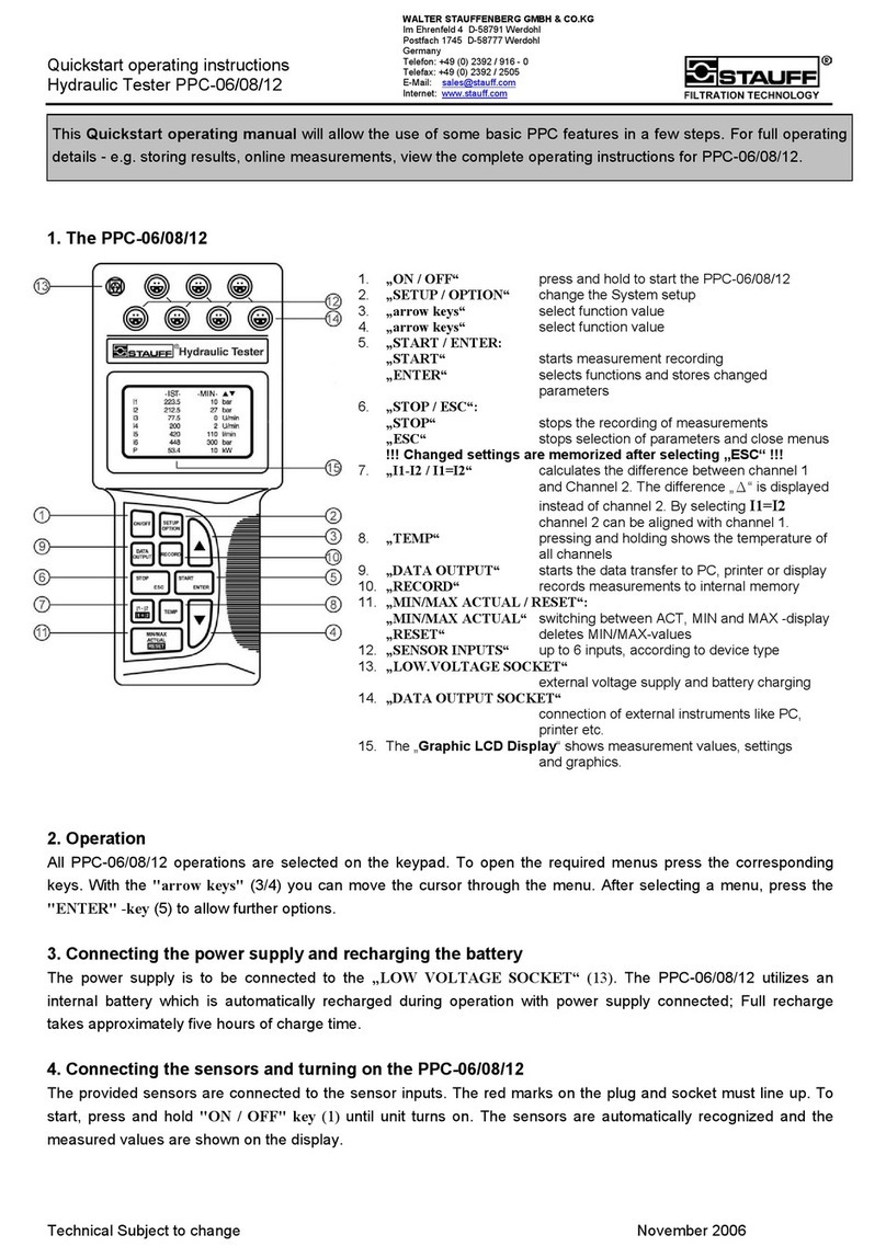
1. „ON / OFF“ is used to switch the instrument on and off.
2. „SETUP / OPTION“ is used to change system settings.
3. The „arrow“ keys are used to select lines and functions.
4. The „arrow“ keys are used to select lines and functions.
5. „START / ENTER“:
„START“ is used to start data (measurement) recording.
„ENTER“ is used to poll sub-functions and accept (memorize) changed function
values.
6. „STOP / ESC“:
„STOP“ is used to stop data (measurement) recording.
„ESC“ is used to stop the function value changing and to close sub-functions. The
previous menu is displayed.
!!! Changed settings won’t be recalled !!!
7. „I1-I2 / I1=I2“ is used for calculation of the difference between measurement channel
1 and measurement channel 2. The value displayed on channel 2 is the difference I1
– I2. It is possible to align I2 on I1. The I1=I2 key sets measurement channel 2 equal
to measurement channel 1 (balancing function).
8. After pressing and holding “TEMP“ the temperature data of all channels are shown.
9. „DATA OUTPUT“ is used to start data output to PC, printer or display.
10. „RECORD“ is used to record and store measurements.
11. „MIN/MAX ACTUAL / RESET“:
„MIN/MAX ACTUAL“ switches display to ACTUAL, MINIMUM and MAXIMUM.
„RESET“ deletes MIN/MAX-values.
12. Up to 6 sensors from the PPC 06/08/12 -program can be simultaneously connected
to the “SENSOR INPUTS“. They are automatically recognised by the instrument. An
adapter is necessary for auxiliary sensors, current and voltage measurements.
13. „LOW-VOLTAGE SOCKET“ enables external voltage supply and battery charging
via power supply unit.
14. External instruments like PC, printer, etc. are connected to the “DATA OUTPUT
SOCKET“.
15. The Graphic LCD display shows measurement values, settings and graphics.

Operating Instructions Hydraulic Tester PPC-06/08/12
9
3.1 Operating the PPC-06/08/12
The main functions of the instrument, such as measuring and displaying, recording
measurements („RECORD“), data output („DATA OUTPUT“) and changing the instrument
settings („SETUP / OPTION“) are selected directly through the keyboard. The „arrow“ keys
select the desired menu. „ENTER“ brings up the selected menu item. The menu item
accompanying function value (parameter) is highlighted.
Changing of the function values is done with the “arrow“ keys. Pressing “ENTER“ confirms
and stores the selected value.
3.1.1 Switching on the PPC
Press “ON / OFF“ for two seconds to switch on the instrument. The current battery state of
the rechargeable battery is shown on the display for a short time.
The version number indicates the internal manufacturing key.
The current battery state is given in percent and illustrated with the black section of the
battery on the display. If the battery state is lower than 40 % you will find the message “BAT.
SERVICE STATUS” on the display.
If the battery state is 0 % you have to use an external voltage supply. The rechargeable
battery will then be charged automatically.
After approx. 8 seconds the display switches to simple measured value representation and
shows the actual measurement values (ACT-values)
STAUFF TEST
PPC-12 3778R9-10101
BATT: LEVEL <=50%
In - ACT 56
1 223,6 bar
2 212,5 bar
3 77.5 U/min
4 200 U/min
5 420 l/min
6 448 bar
P 53.4 kW

Operating Instructions Hydraulic Tester PPC-06/08/12
10
3.1.2 Display
The graphic LCD-display of the instrument has a maximum resolution of 128 x 64 pixel. The
visible area is 72 x 40 mm. Using an 8-line representation (status, 6 channels (inputs),
optional line) the digit height is 4,2 mm. Indicated values are adapted to the display size
through an automatic digit height setting, for example if there are less then four channels for
the actual values the numbers on the display will have double the size.
The text mode is separated into 8 lines and 4 columns. The first column shows the selected
channel. The second and third columns show the corresponding measured values. Here it is
possible to choose between four different options:
ACT Æactual measured value (third column empty)
ACT - MIN Æactual measured value – minimum value
ACT - MAX Æactual measured value – maximum value
MIN - MAX Æminimum value – maximum value
Column four shows the UNITS of the measured values.
The first line of the display shows the status (i.e. recording, memorizing), the measured value
identifier (ACT, MIN, MAX) or the menu name. Lines 2 – 7 show the measured values. Line 8
is an optional line, in which calculated values like P (power) and V (volume) are shown.
Curves from measured values can be displayed in the graphic mode

Operating Instructions Hydraulic Tester PPC-06/08/12
11
3.1.3 Connection of sensors
The sensors are connected to the input jack of the PPC-06/08/12 via an interconnection
cable. The red points on the plugs must correspond with the red points on the sockets. The
measuring range is scaled through automatic sensor recognition and the measured value will
be shown on the display.
Attention!!
Safety Instructions for using sensors (i.e. the 1.000 bar pressure sensor):
Please pay attention to built in test points acc. to rated nominal pressure and
specified safety factors.

Operating Instructions Hydraulic Tester PPC-06/08/12
12
3.1.4 Operation and display control
The navigating and programming of the PPC-06/08/12 unit is basically done as follows.
For example look at the „SETUP“ menu:
Pressing „SETUP / OPTION“
opens the „SETUP“ –menu.
By pressing the „arrow“-keys
the Cursor can be navigated
through the menu.
By pressing „arrow“ –key up,
the cursor jumps from
„AUX.SENSOR“ to „CONTRAST (%)“
By pressing „Start / Enter“ the
-cursor jumps right to the function
value, contrast can now be adjusted
with the arrow keys.
By pressing „Start / Enter“
once again, the value will be
confirmed and the cursor jumps
back to „CONTRAST (%)“.
Depending on the menu item, after
pressing „Start / Enter“, a new menu
is opened.
The submenu „INPUT“ of the
menu item „AUX.SENSOR>“
is opened.
ESC -- SETUP -- 56
CONTRAST (%) 50
AUX. SENSOR>
COMBINATION>
RECORD SETUP>
DEVICE SETUP>
BATT.SERVICE>
SYSTEM SETUP>
ESC -- SETUP -- 56
CONTRAST(%) 50
AUX. SENSOR>
VERKNUEPFUNG>
RECORD SETUP>
DEVICE SETUP>
BATT.SERVICE>
SYSTEM SETUP>
ESC -- SETUP -- 56
CONTRAST (%) 50
AUX. SENSOR>
COMBINATION>
RECORD SETUP>
DEVICE SETUP>
BATT.SERVICE>
SYSTEM SETUP>
ESC -- SETUP -- 56
CONTRAST (%) 50
AUX. SENSOR>
COMBINATION >
RECORD SETUP>
DEVICE SETUP>
BATT.SERVICE>
SYSTEM SETUP>
ESC -- INPUT 56
ANALOGUE> I1
FREQUENCY>
ESC -- SETUP -- 56
CONTRAST (%) 50
AUX. SENSOR>
COMBINATION>
RECORD SETUP>
DEVICE SETUP>
BATT.SERVICE>
SYSTEM SETUP>

Operating Instructions Hydraulic Tester PPC-06/08/12
13
By pressing „Stop / ESC“ the current
menu is closed and the prior menu
is displayed.
The programming of numbers and text is described in chapter 3.1.5, and 3.1.6 respectively.
ESC -- SETUP -- 56
CONTRAST(%) 50
AUX. SENSOR>
COMBINATION >
RECORD SETUP>
DEVICE SETUP>
BATT.SERVICE>
SYSTEM SETUP>

Operating Instructions Hydraulic Tester PPC-06/08/12
14
3.1.5 Number input
When configuring auxiliary sensors (chapter 4.1) the measurement range (i.e. 0 ... 250 bar)
and the corresponding initial and end value (i.e. 0 ... 20 mA) have to be programmed.
The next example shows the number input of an auxiliary sensor.
After selecting a number, this number is highlighted. By pressing the „arrow“ keys, the
former number is deleted, the first digit is highlighted and changed. The first digit of the
number has to be confirmed by pressing „START / ENTER“ and the following digit is
highlighted.
„STOP / ESC“ terminates the input and stores the new number.
Example:
select number
confirm number
ESC -- ANALOGUE -- 56
In1
UNITS: bar
FROM: 0
TO: 600
SIGNAL: mA
FROM: 4
TO: 20
ESC -- ANALOGUE -- 56
In1
UNITS: bar
FROM: 0
TO: 600
SIGNAL: mA
FROM: 4
TO: 20
ESC -- ANALOGUE -- 56
In1
UNITS: bar
FROM: 0
TO: 600
SIGNAL: mA
FROM: 4
TO: 20

Operating Instructions Hydraulic Tester PPC-06/08/12
15
change first digit
confirm first digit
change second digit
confirm second digit
complete number input
ESC -- ANALOGUE -- 56
In1
UNITS: bar
FROM: 5_ _ _ _ _ _ _
TO: 600
SIGNAL: mA
FROM: 4
TO: 20
ESC -- ANALOGUE -- 56
In1
UNITS: bar
FROM: 5 0 _ _ _ _ _ _
TO: 600
SIGNAL: mA
FROM: 4
TO: 20
ESC -- ANALOGUE -- 56
In1
UNITS: bar
FROM: 5 5 _ _ _ _ _ _
TO: 600
SIGNAL: mA
FROM: 4
TO: 20
ESC -- ANALOGUE -- 56
In1
UNITS: bar
FROM: 5 5 _ _ _ _ _ _
TO: 600
SIGNAL: mA
FROM: 4
TO: 20
ESC -- ANALOGUE -- 56
In1
UNITS: bar
FROM: 55
TO: 600
SIGNAL: mA
FROM: 4
TO: 20

Operating Instructions Hydraulic Tester PPC-06/08/12
16
3.1.6 Text input
For functions like auxiliary sensors (chapter 4.1), data recording (chapter 5.3) and user ID
(see chapter 6.3.3), text input is mandatory.
After selecting a text line, the menu “TEXT” is displayed.
New text is shown on the bottom line next to „TEXT“ as it is entered. New character’s can be
selected by pressing the „arrow“ keys. By holding down the arrow key the cursor moves
faster through the text input field. „START / ENTER“ confirms the selected character and
highlights the next character. „_“ represents a space. The text input can be completed by
pressing „STOP / ESC“. The text displayed under the heading TEXT is stored and then the
display returns to the previous active menu.
select new character
confirm new character
select next character
-- TEXT -- 56
AaBbCcDdEeFfGgHhIiJj
KkLlMmNnOoPpQqRrSsTt
UuVvWwXxYyZz%/_
0123456789.-+
STORE = STOP/ESC
15 CHARS MAX
TEXT: MASCH3
-- TEXT -- 56
AaBbCcDdEeFfGgHhIiJj
KkLlMmNnOoPpQqRrSsTt
UuVvWwXxYyZz%/_
0123456789.-+
STORE = STOP/ESC
15 CHARS MAX
TEXT: MASCH3 _ _ _
-- TEXT -- 56
AaBbCcDdEeFfGgHhIiJj
KkLlMmNnOoPpQqRrSsTt
UuVvWwXxYyZz%/_
0123456789.-+
STORE = STOP/ESC
15 CHARS MAX
TEXT: MASCH3 _ _ _

Operating Instructions Hydraulic Tester PPC-06/08/12
17
confirm character
terminate text input and store text

Operating Instructions Hydraulic Tester PPC-06/08/12
18
3.2 Measurement and display
The following chapters describe the different presentation of measured values.
3.2.1 Display of measured values (ACT – MIN - MAX)
The measured values in the display can be shown as ACT (actual), MIN (minimum) and MAX
(maximum) values. There are several display options. The basic configuration shows the
ACT values.
When pressing “MIN/MAX ACTUAL / RESET“ the following values are shown:
This display shows the ACT value and the MIN value.
The following display shows the ACT and MAX value.
In - ACT 56
1 223,6 bar
2 212,5 bar
3 77.5 U/min
4 200 U/min
5 420 l/min
6 448 bar
P 53.4 kW
In - ACT MIN 56
1 223,6 10 bar
2 212,5 27 bar
3 77.5 0 U/min
4 200 2 U/min
5 420 410 l/min
6 448 300 bar
P 53.4 kW
In - ACT MAX 56
1 223,6 320 bar
2 212,5 220 bar
3 77.5 80,0 U/min
4 200 400 U/min
5 420 420 l/min
6 448 555 bar
P 53.4 kW

Operating Instructions Hydraulic Tester PPC-06/08/12
19
The next display shows the MIN and MAX value.
By pressing „MIN/MAX ACTUAL / RESET“ once again all actual values of channel 1 are
shown. Using the „arrow“ keys shows the values of the sensors.
select different sensor
By pressing „STOP / ESC“ all channels can be shown on the display again.
The display of all actual measured values from one sensor can be obtained by selecting the
corresponding input with “ENTER“.
select Sensor / Input I2
In - MIN MAX 56
1 10 320 bar
2 27 220 bar
3 0 80,0 U/min
4 2 400 U/min
5 410 420 l/min
6 300 555 bar
P kW
I1 56
345,6bar
Min=131 Max=434
T=55°C
I3 56
162,6bar
Min=145 Max=201
T=63°C
In - ACT 56
1 223,6 bar
2 212,5 bar
3 77.5 U/min
4 200 U/min
5 420 l/min
6 448 bar
P 53.4 kW

Operating Instructions Hydraulic Tester PPC-06/08/12
20
confirm sensor / input I2
The values of the other sensors are shown by using the “arrow“ keys.
By pressing “STOP / ESC“ the values of all sensors return on the display.
back to previous display
I2 56
212,5bar
Min=131 Max=434
T=55°C
In - ACT 56
1 223,6 bar
2 212,5 bar
3 77.5 U/min
4 200 U/min
5 420 l/min
6 448 bar
P 53.4 kW
This manual suits for next models
2
Table of contents
Other STAUFF Measuring Instrument manuals
