EM Acoustics Halo Compact User manual
System User Manual
v7 December 2019
LOUDSPEAKERS REDEFINED

Page 2 of 60
HALO Compact User Manual
V7 December 2019
Contents
DECLARATION OF CONFORMITY ................................................................................................................ 5!
1.0 - Introduction ............................................................................................................................................. 6!
2.0 - HALO Compact System Components..............................................................................................7!
HALO-C ............................................................................................................................................................7!
HALO-CS..........................................................................................................................................................7!
FG-HALO-C .....................................................................................................................................................8!
SM-HALO-C.....................................................................................................................................................8!
FG-HALO-C .....................................................................................................................................................8!
HM-HALO-C.................................................................................................................................................... 8!
3.0 – Safety.........................................................................................................................................................9!
System Overview ........................................................................................................................................9!
Secondary Safeties.................................................................................................................................. 10!
Safety Inspections .............................................................................................................................. 10!
4.0 – Ease Focus 3......................................................................................................................................... 11!
5.0 – Rigging Overview ............................................................................................................................... 12!
5.1 - FG-HALO-C Overview.................................................................................................................... 12!
5.2 - FG-HALO-C Instruction Label..................................................................................................... 14!
5.3 - Attaching Accessories to the FG-HALO-C.................................................................................. 15!
FG-HALO-C Extension Bar ..................................................................................................................... 15!
HM-HALO-C................................................................................................................................................. 16!
5.4 - SM-HALO-C Overview........................................................................................................................ 17!
5.5 - SM-HALO-C Stand Adapter.............................................................................................................. 18!
Attaching Stand Adapter to SM-HALO-C ......................................................................................... 18!
6.0 - HALO-CS Rigging ................................................................................................................................ 19!
HALO-CS Overview .................................................................................................................................. 19!
6.1 - Rigging the HALO-CS to an FG-HALO-C................................................................................. 20!
6.2 - Rigging Two HALO-CS together............................................................................................... 22!
7.0 - HALO-C Rigging................................................................................................................................... 24!
HALO-C Overview..................................................................................................................................... 24!
7.1 - Rigging the HALO-C to an FG-HALO-C.................................................................................... 26!
7.2 - Rigging the HALO-C to an SM-HALO-C................................................................................... 28!
7.3 - Rigging two HALO-C together .................................................................................................. 30!

Page 3 of 60
HALO Compact User Manual
V7 December 2019
7.4 - Rigging HALO-CS and HALO-C................................................................................................... 31!
8.0 – Ground-stacking HALO-C.................................................................................................................. 32!
8.1 - Ground-stacking HALO-C on FG-HALO-C ............................................................................... 32!
8.2 - Ground-stacking HALO-C on HALO-CS.................................................................................... 33!
9.0 – Flying HALO-C – EM Standard Flightcases................................................................................. 34!
10 – Maximum Element System Configurations................................................................................ 35!
10.1 - HALO-C & HALO-CS Flown – FG-HALO-C ............................................................................. 35!
10.2 - HALO-C Flown – SM-HALO-C.................................................................................................... 36!
10.3 - HALO-C Ground Stacked – FG-HALO-C ................................................................................. 37!
10.4 - HALO-C Ground Stacked – HALO-CS...................................................................................... 37!
11.0 – Connecting Elements...................................................................................................................... 38!
11.1 - Connecting HALO-C .................................................................................................................... 38!
11.2 - Connecting HALO-CS.................................................................................................................. 38!
12.0 – Powering the System..................................................................................................................... 39!
12.1 - Amplifier and Processing Requirements ............................................................................ 39!
12.1.1 – Amplifier Requirements.................................................................................................... 39!
12.1.2 - Connections .......................................................................................................................... 40!
12.1.3 - Connector Options.............................................................................................................. 40!
12.2 - Presets and Settings.................................................................................................................. 41!
12.2.1 - Preset Description.............................................................................................................. 41!
12.2.2 - Geometric Delay .................................................................................................................. 43!
12.2.3 - Applying EQ........................................................................................................................... 43!
12.3 - Use with the DQ Series Advanced System Amplifiers................................................... 44!
12.3.1 - Connections .......................................................................................................................... 44!
12.3.2 - Preset Recall......................................................................................................................... 45!
12.4 – Use with the DSC48 Controller .............................................................................................. 45!
12.5 - System Connectivity.................................................................................................................. 46!
12.5.1 - Maximum number of elements per amplifier............................................................ 46!
12.5.2 - Cable Length and Specification..................................................................................... 46!
13.0 - Splay Angles – Above 10 degree................................................................................................ 47!
14.0 - Servicing Information..................................................................................................................... 48!
HALO-C: Removing the AMT high frequency drive unit............................................................ 48!
HALO-C: Removing the LF Drive Unit .............................................................................................. 49!
HALO-CS Subwoofer – Removing the LF drive unit ..................................................................... 50!

Page 4 of 60
HALO Compact User Manual
V7 December 2019
Appendix A – Technical Specifications.................................................................................................. 51!
HALO-C 2-way passive compact line array element ................................................................... 51!
HALO-CS compact flyable reflex subwoofer.................................................................................. 52!
Appendix B – Technical Drawings ........................................................................................................... 53!
Appendix C – Spare Parts List ................................................................................................................... 59!
Limited Warranty...................................................................................................................................... 60!
Warranty Coverage.................................................................................................................................. 60!
Returning your EM Acoustics loudspeaker..................................................................................... 60!

Page 5 of 60
HALO Compact User Manual
V7 December 2019
DECLARATION OF CONFORMITY
The products contained within this manual conform to the
requirements of the EMC Directive 89/336/EEC, amended by
92/31/EEC and to the requirements of the Low Voltage Directive
73/23/EEC amended by 93/68/EEC.
EMC Emission EN55103-1:1996
Immunity EN55103-2:1996
Electrical Safety EN60065:1993
RECYCLING
This product and its packaging constitute the applicable product according
to the WEEE directive. Please ensure that at the end of the working life of
this product, it is disposed of sensibly in accordance with local and national
recycling regulations. The packaging supplied with this product is
recyclable. Please retain all packaging, however if disposing of this
packaging please ensure that you comply with local recycling regulations.
These products also all comply to the RoHS Directive 2002/95/EC.

Page 6 of 60
HALO Compact User Manual
V7 December 2019
1.0 - Introduction
Thank you for purchasing the revolutionary HALO Compact line array system from EM
Acoustics. The entire HALO system family has been designed and rigorously tested to
give you the utmost in sonic performance and many years of reliable, trouble-free
operation. Please take the time to read this user manual thoroughly to ensure you get
the best performance from your system and to ensure you set it up correctly and safely.
If you have any questions or are in any doubt whatsoever about any aspect of your HALO
system, please do not hesitate to contact us directly or your local EM Acoustics
representative.
The HALO Compact system is one of the only line array loudspeaker systems in the world
to utilize genuine ribbon transducers for high frequency reproduction, resulting in
incredible detail and clarity as well as superior feedback rejection. The ribbon driver,
coupled with the patent-pending diffraction manifold means HALO Compact offers a
vastly superior consistent 95-degree horizontal coverage pattern. Added to this is the
incredibly intuitive flying system, renowned EM Acoustics passive crossover technology
and the one-to-one customer support that EM Acoustics is known for.
This manual contains all the information you should need on topics of set up, amplifier
connection, flying & stacking and basic service. If you feel we have missed anything, or
you have a question not covered by this manual, please visit our website
www.emacoustics.co.uk and send us a message or give us a call – we’re only too happy to
help.
Unpacking
Please take care when unpacking your loudspeaker system. Once unpacked, please
inspect each enclosure thoroughly for any transit damage and in the case of any damage
please notify your carrier immediately. It is the responsibility of you, the consignee, to
instigate any claim. Please retain all original packaging in case of future re-shipment.
Page 7 of 60
HALO Compact User Manual
V7 December 2019
2.0 - HALO Compact System Components
The HALO Compact system comprises two loudspeaker models and associated flying
hardware. Details of the different components are given below – all enclosures and flying
grids work on the same principles and use similar if not identical hardware.
HALO-C
2-way passive line array
element
HALO-CS
compact flyable subwoofer
FEATURES & BENEFITS
• Signature EM Acoustics passive crossover for unmatched frequency and phase response
• Extremely consistent 95-degree horizontal dispersion for predictable results in use
• Small footprint and low weight ensure a discreet system that is easy to rig
• HIgh power-to-size ratio
• Passive design reduces amplifier channel count and minimises processing requirement
• Lightweight plywood enclosure offers significantly less panel flexure than plastic designs
• Intuitive, safe rigging system for both flown and groundstacked systems
• Full data for EASE and EASE Focus prediction packages
KEY SPECIFICATIONS
ENCLOSURE TYPE:
DRIVE UNITS:
FREQUENCY RESPONSE:
NOMINAL DISPERSION1:
MAXIMUM SPL2:
NOMINAL IMPEDANCE:
DIMENSIONS (HxWxD):
NET/SHIPPING WEIGHT:
2-way passive line array element
8” LF, 8” AMT HF (all neodymium)
75Hz - 20kHz +/-3dB
95 horizontal, vertical dependent on array config
124dB continuous, 130dB peak
8 ohms
216 (8.5) x 492 (19.4) x 400 (15.7) mm/(ins) - enclosure only
252 (9.9) x 524 (20.6) x 400 (15.7) mm/(ins) - extremities
17/19kg (37.4/41.8lbs)
FEATURES & BENEFITS
• High power 15” drive unit offers useable LF performance from a compact enclosure
• Small footprint and low weight ensure a discreet system that is easy to rig
• High power-to-size ratio
• Lightweight plywood enclosure offers significantly less panel flexure than plastic
designs
• Intuitive, safe rigging system for both flown and groundstacked systems
• Full data for EASE and EASE Focus prediction packages
• Represents 2 x HALO-C element in an array, both for weight and physical size
• Useable for ground stacks without flying grid
KEY SPECIFICATIONS
ENCLOSURE TYPE:
DRIVE UNITS:
FREQUENCY RESPONSE:
NOMINAL DISPERSION1:
MAXIMUM SPL2:
NOMINAL IMPEDANCE:
DIMENSIONS (HxWxD):
NET/SHIPPING WEIGHT:
Compact flyable reflex subwoofer
15” neodymium LF drive unit
40Hz - 120Hz +/-3dB
omnidirectional
126dB continuous, 132dB peak
8 ohms
438 (17.2) x 492 (19.4) x 600 (23.6) mm/(ins) - enclosure only
438 (17.2) x 524 (20.6) x 600 (23.6) mm/(ins) - extremities
36/38kg (79.2/83.6lbs)

Page 8 of 60
HALO Compact User Manual
V7 December 2019
FG-HALO-C
Master Flying
Grid
The FG-HALO-C is the master flying grid for the system, and provides
a means of safely and swiftly flying arrays of HALO-C elements,
HALO-CS subwoofers or a combination of both. Up to 24 HALO-C
elements, or a combination of HALO-C and HALO-CS subwoofers
(where one HALO-CS would replace two HALO-C elements) can be
safely flown with a 10:1 safety factor.
When inverted, the FG-HALO-C grid provides a means of ground
stacking HALO-C elements direct onto stages or onto larger
subwoofer systems if required, with rubber feet to provide grip. A
mounting plate for the TEQSAS LAP-TEQ laser inclinometer system is
also included as standard to assist with array aiming when in use.
(LAP-TEQ system not included).
SM-HALO-C
Simple Flying
Frame
The SM-HALO-C flying frame serves two purposes – first as a low-
cost solution for flying small numbers of HALO-C elements in both
temporary and fixed installations, and secondly as a means of
mounting up to three HALO-C enclosures from a distance pole or
loudspeaker stand.
The SM-HALO-C is supplied with a 35mm loudspeaker stand adapter,
and has a variety of 11mm diameter holes to either bolt directly in
fixed installations, or to attach hook clamps for swift suspension of
small arrays from boom arms or trusses.
FG-HALO-C
Extension Bar
The extension bar provides additional pickup points to the front or
rear of the array for more severe down or up-tilt angles. Secured to
the FG-HALO-C grid by two 3/8” ball lock pins, the extension bar
utilises the same 1-ton shackles for array pickup and safety points.
The extension bar is symmetrical so can be used to provide
extension to the pickup points either at the front or the rear of the
grid.
HM-HALO-C
Hook Clamp
Adapter
The HM-HALO-C adapter allows the FG-HALO-C flying grid to be
suspended from a single point using standard half-couplers or trigger
clamps. A high-tensile bolt secures the HM-HALO-C into the desired
position on the FG-HALO-C central spine, and a 13mm diameter hole
in the top of the mount allows attachment of the desired clamping
device.

Page 9 of 60
HALO Compact User Manual
V7 December 2019
3.0 – Safety
System Overview
The flying system for HALO Compact has been specifically designed to be flexible, intuitive and
reliable. Please read this section of the user manual extremely carefully as the rigging of
loudspeakers is a very serious matter with potentially fatal consequences should anything go
wrong. If you are in ANY DOUBT WHATSOEVER, contact a reputable rigging company or your
local EM Acoustics representative.
IMPORTANT SAFETY CONSIDERATIONS
The HALO Compact rigging system has been designed and constructed to a very high standard of
safety, and tested to demanding specifications. To ensure the highest standards of safety, the
following information on array assembly must be exactly followed and understood.
Only use EM Acoustics recommended rigging hardware and accessories, which are specifically
designed for the purpose. Do not use HALO Compact flying hardware for any other loudspeaker
system – the components are specifically designed to work with the HALO Compact system and
are not interchangeable with any other EM Acoustics loudspeaker product or any other
loudspeaker system. The use of HALO Compact flying hardware with other manufacturers’
systems may compromise the safety standards and EM Acoustics, and its parent company, are in
no way liable for any loss, damage or injury caused by such practice.
Do not modify or alter the HALO Compact hardware or accessories, nor use them in any way other
than that described in this manual. Rigging components supplied as part of the HALO Compact
system are in no way interchangeable and should not be used as such.
The component parts of the HALO Compact rigging assembly should only be assembled in the
manner described in this manual, using the fasteners and fixings stated herein. The use of
fasteners and methods of assembly not described in this manual may result in an unsafe assembly
and as such EM Acoustics will not be responsible for any loss, damage or injury caused by such
practice. Welding, drilling or any other means of modifying any part of the flying hardware or
permanently fixing components to each other is strictly forbidden.
Rigging assemblies must only be assembled using the appropriate parts and fixings as described
in this manual, explicitly following the assembly instructions given herein. Rigging components
must only be fixed to EM Acoustics HALO Compact loudspeaker systems, using the correct cabinet
location points, assembly methods and fasteners specifically described within this manual.
Walls, floors and ceilings must be capable of supporting the actual load placed upon them. The
rigging hardware must be safely and securely fixed to both the loudspeaker system and the
supporting structure.
When mounting components on walls, floors or ceilings ensure that all fixings and fasteners used
are of an appropriate size and load rating. Wall and ceiling claddings, and the
construction/composition of walls and ceilings also need to be taken into consideration when
determining if a given suspension method is safe.

Page 10 of 60
HALO Compact User Manual
V7 December 2019
Secondary Safeties
It is best practice to ensure that all loudspeakers flown in any given environment should be
provided with a second, independent and properly rated safety suspension point in addition to the
principle load bearing means of suspension. Steel wire ropes or steel chains of an approved
construction and load rating only may be used as secondary safeties. Plastic covered steel chains
may not be used as secondary safeties under any circumstances. Also ensure that all local and
national laws are complied with when determining your primary and secondary suspension points.
Safety Inspections
Carefully inspect all flying system components prior to use for defects or signs of damage prior to
assembling a HALO Compact array. If any components damaged or you suspect them to be
damaged, DO NOT USE THEM.
Regular scheduled tests – which are much more rigorous than visual inspections – of all rigging
components must also be carried out. Safety legislation, and test/inspection requirements, will
vary from country to country and as such it is the user’s responsibility to ensure that local
regulations are adhered to. In most cases, annual independent tests & inspections carried out by
a suitably approved and qualified inspector will be required.
EM Acoustics recommends detailed logbooks be kept of all inspections and load tests to ensure an
accurate record is kept of the testing for each EM Acoustics rigging accessory.
When flying any loudspeaker system, always wear protective headwear, footwear and eye
protection in accordance with local regulations.
The AMT drive unit has a very powerful magnetic field and as such, care should be taken to avoid
items becoming magnetized to the outside of the enclosure.
The rigging of a flown loudspeaker system may be dangerous if not undertaken by a suitably
experienced and qualified rigger. Installation & fixing of all hanging points should only be carried
out by a professional rigger in accordance with local legislation as well as the rules of the venue.
The house rigger and/or venue manager must always be consulted.
Page 11 of 60
HALO Compact User Manual
V7 December 2019
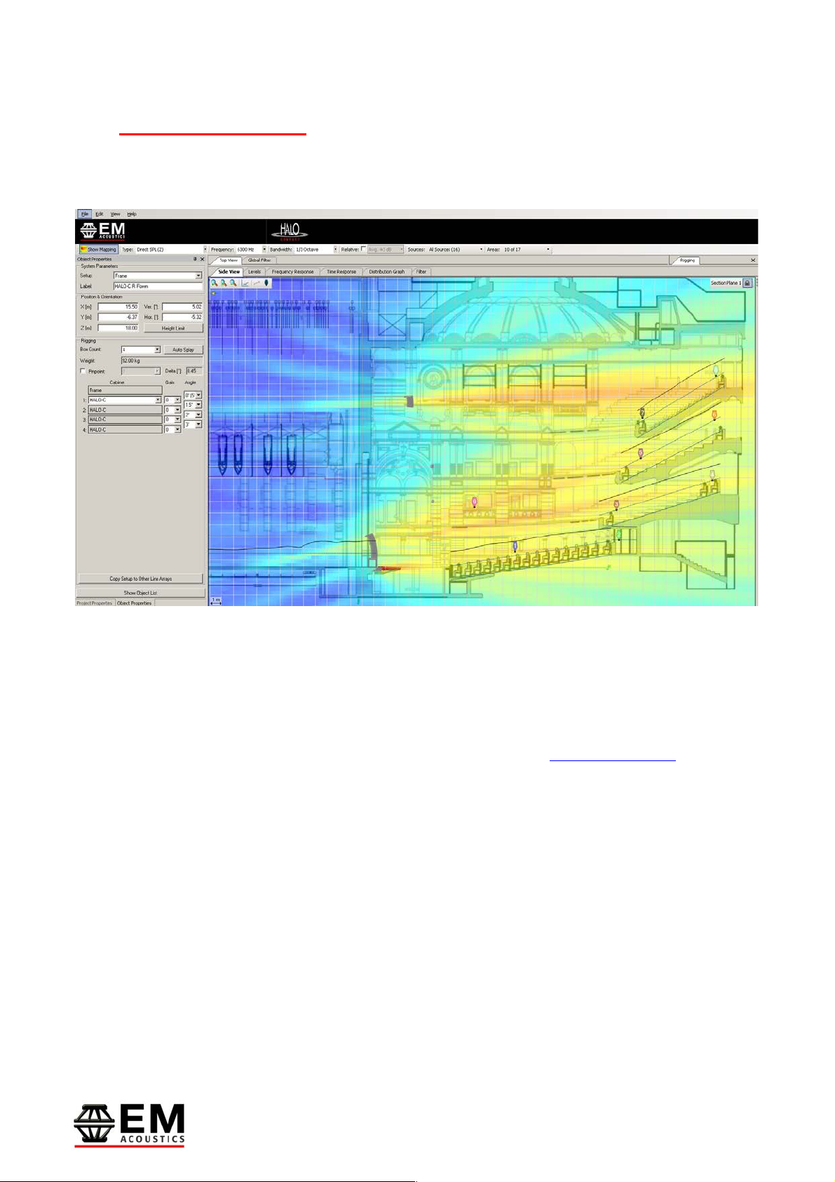
4.0 – Ease Focus 3
For safety and acoustic reasons, it is advised that users familiarize themselves with Ease Focus
3. Along with providing the user with accurate simulations for setting up HALO Compact, it also
provides importing safety information with regards to load limits.
Ease Focus 3 can be downloaded for free from the AFMG website at http://focus.afmg.eu and is
currently available as a stand-alone application for Windows (XP or Higher) only. It can also be
downloaded directly from the EM Acoustics website with all the current product files embedded.
Tutorials for Ease Focus 3 are available from with the application itself.
For training on the design and implementation of HALO Compact including the specific use of
Ease Focus 3, please contact your local distributor.

Page 12 of 60
HALO Compact User Manual
V7 December 2019
5.0 – Rigging Overview
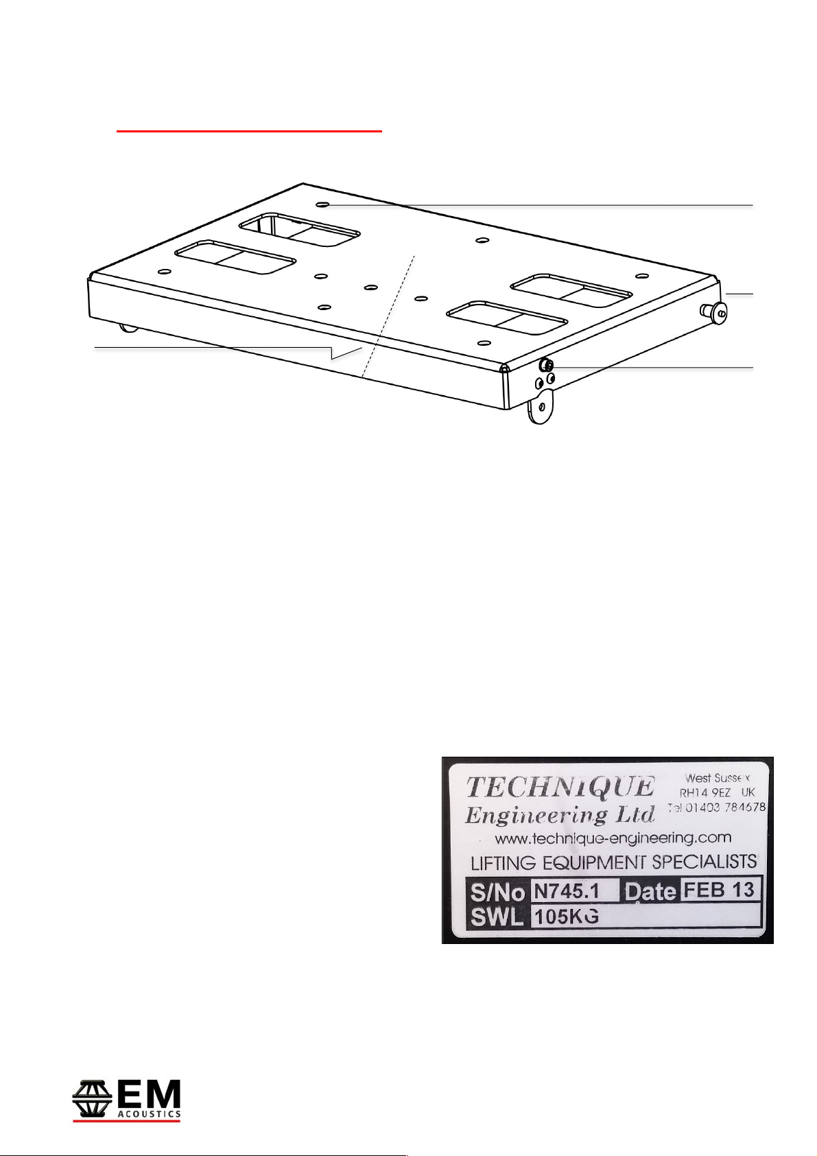
5.1 - FG-HALO-C Overview
[5
]
[1
]
[2
]
[3
]
[4
]
[6
]

Page 13 of 60
HALO Compact User Manual
V7 December 2019
[1] – Rubber Feet
[2] – Hanging Point
[3] – Laser Mounting Plate
[4] – FG-HALO-C Instruction Label
[5] – Quick Release Pin
[6] – Captive Front Link
The rubber feet are used when the FG-HALO-C grid is
inverted for ground stack use to provide a high friction
contact between the grid and the ground surface.
24 x 12mm diameter pickup points are provided on the
center spine of the grid to allow for varied vertical
angles when using a single flying point. The correct
point for a desired angle can be determined by using
Ease Focus 3. When using a fixed pick point, Ease
Focus 3 will issue a Delta figure to show the
difference between the desired angle and the
achievable angle from this point taking the center of
gravity from the array shape into account.
A mounting plate for the TEQSAS LAP-TEQ laser
inclinometer system is also included as standard to
assist with array aiming when in use. (LAP-TEQ system
not included).
The Instruction labels on each side of the grid provide
information for the pin points for various array
configurations as well as up and down tilt options and
a quick reference for the grid’s safe working loads.
See page 14 for a detailed view and description.
Quick release pin shown locking the front link in the
HALO-C position.
The captive front link allows for easy selection
between flying a HALO-CS or a HALO-C to the flying
frame. The link can also be stowed within the frame
to protect it when not attached to a loudspeaker.

Page 14 of 60
HALO Compact User Manual
V7 December 2019
Colour identified holes denote captive link
pin points for flying the HALO-CS, HALO-C or
the stow position.
Colour identified holes denote rear
pin points for flying the HALO-CS or
HALO-C.
5.2 - FG-HALO-C Instruction Label
Rear Link information box gives a
quick reference to the uptilt and
downtilt angles relative to the grid.
Information box at the rear of the grid
gives a quick reference to maximum
loads possible on the FG-HALO-C with
various combinations of boxes
Page 15 of 60
HALO Compact User Manual
V7 December 2019
Attach the Extension Bar in
place by using the quick release
pins attached to it.
The Extension Bar can also be
fitted in reverse with the
extension to the front of the
FG-HALO-C to allow for extra up
tilt if required
5.3 - Attaching Accessories to the FG-HALO-C
FG-HALO-C Extension Bar
Lower the Extension Bar over the
center spine of the FG-HALO-C
and locate the two lower holes
on the Extension Bar with the
two lower holes on the center
spine.
NOTE: Do not attempt to attach
the Extension Bar to the upper
holes on the FG-HALO-C Spine

Page 16 of 60
HALO Compact User Manual
V7 December 2019
Use Ease Focus 3 to select the
correct pickup point for the
desired vertical angle of the FG-
HALO-C
Use the M12 bolt and washers
supplied with the HM-HALO-C
to secure the adapter in place
Adapters such as rigging eyes
or clamps can be attached to
the HM-HALO-C to give the
desired method of flying.
HM-HALO-C
Page 17 of 60
HALO Compact User Manual
V7 December 2019
Quick release pin point for rear of HALO-C
Quick release pin point for front of HALO-C
A Manufacturers safety information label is attached
to the inside of the SM-HALO-C to identify the Serial
Number, Date of Manufacture and SWL.
5.4 - SM-HALO-C Overview
[1] – Fixing Points
[2] – Rear Pin Point
[3] – Front Pin Point
[4] – Safety Information Label
[1
]
[2
]
[3
]
[4
]
9 x 11mm fixing holes for attaching various industry
standard attachments such as speaker stand mount,
hook clamps and half couplers. Holes can also be used
to bolt the SM-HALO-C grid to another surface.
Page 18 of 60
HALO Compact User Manual
V7 December 2019
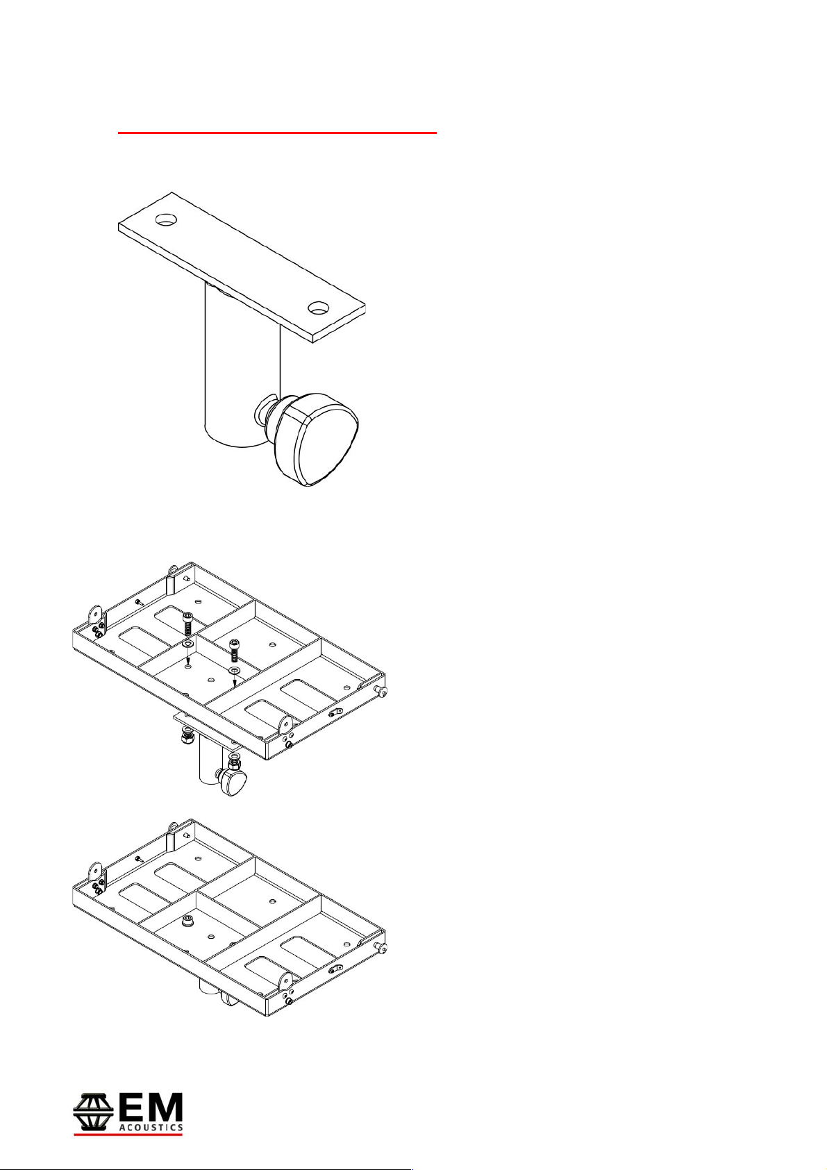
5.5 - SM-HALO-C Stand Adapter
Attaching Stand Adapter to SM-HALO-C
The SM-HALO-C is supplied with a 35mm speaker
stand adapter. In this combination, the SM-HALO-C will
safely support up to 3 x HALO-C on a speaker stand
dependent on the SWL of the stand used. Please
refer to the speaker stand manufacturer’s
documentation for SWLs.
Use the M10 bolts and washers supplied with
the SM-HALO-C to attach the Stand Adapter
through the holes shown in the diagram.

Page 19 of 60
HALO Compact User Manual
V7 December 2019
Upper rear link has options for attaching to FG-HALO-
C, to the underside of another HALO-CS, or to be
stowed when not in use.
Quick release front pin point to receive link from either
FG-HALO-C or from underside of another HALO-CS.
Quick release rear pin point to receive link from either
HALO-C or another HALO-CS.
Lower from link has options for attaching another
HALO-CS, a HALO-C, or to be stowed when not in use.
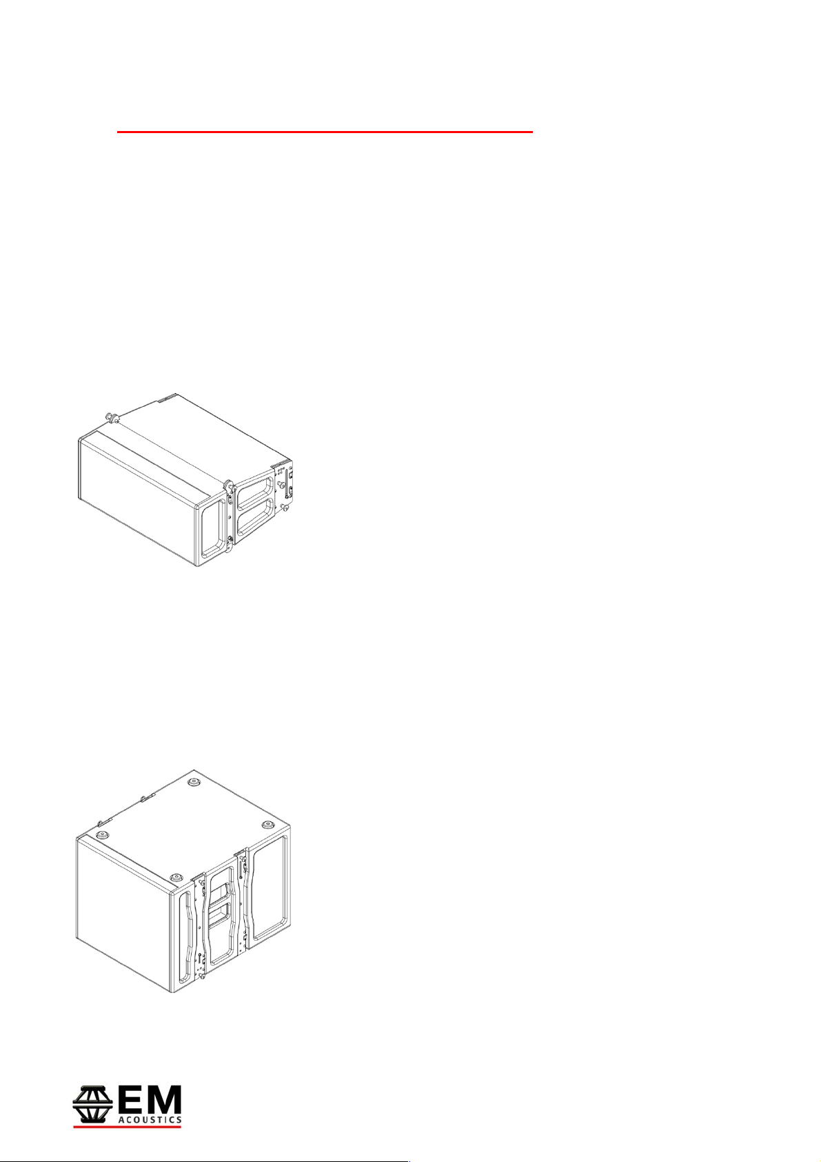
6.0 - HALO-CS Rigging
HALO-CS Overview
[1] – Rubber Feet
[2] – Upper Rear Link
[3] – Upper Front Pin Point
[4] – Lower Rear Pin Point
[5] – Lower Front Link
[1
]
[2
]
[4
]
[3
]
[5
]
The rubber feet are used when the HALO-CS is
inverted for ground stack use to provide a high friction
contact between the speaker and the ground surface.

Page 20 of 60
HALO Compact User Manual
V7 December 2019
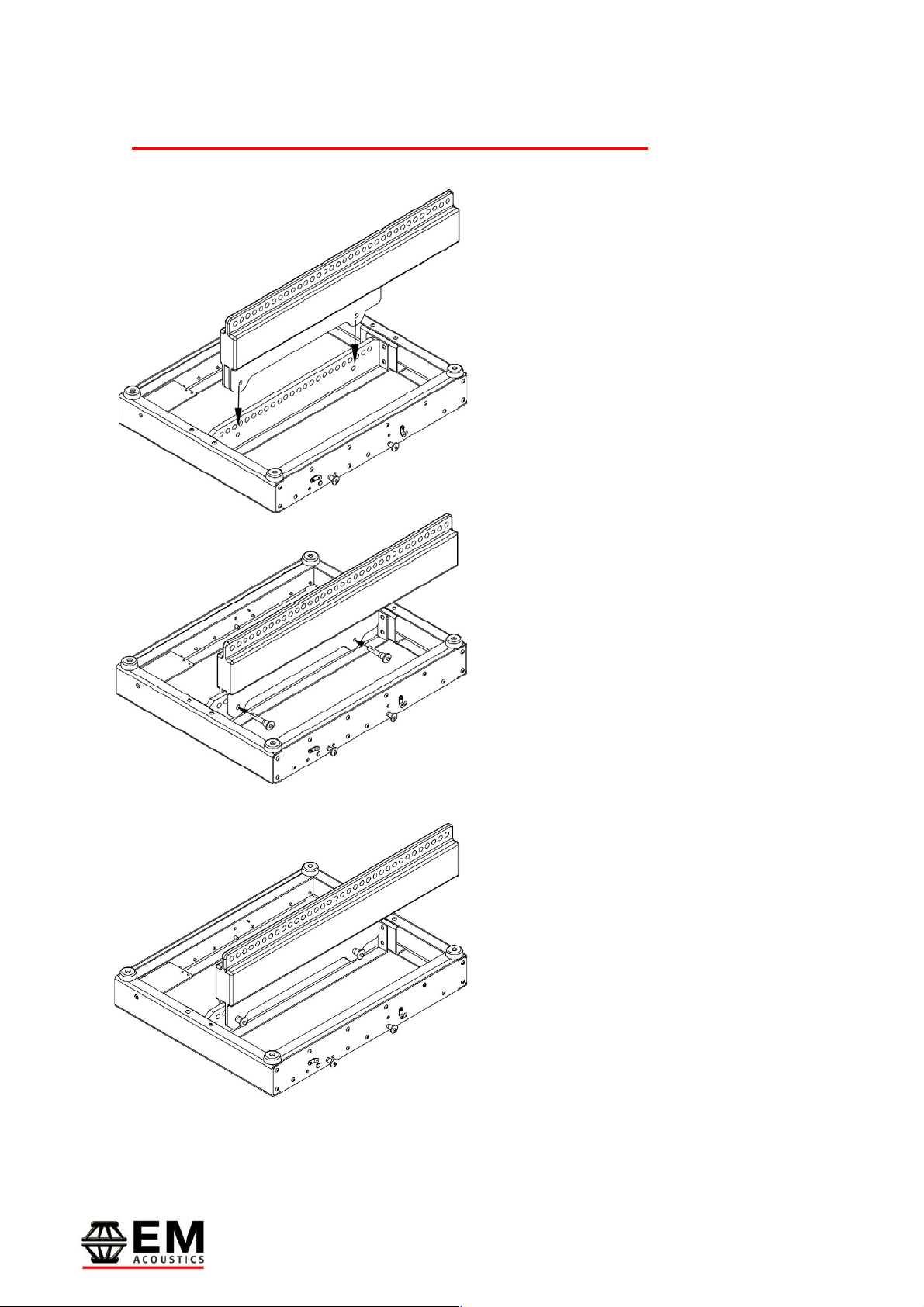
6.1 - Rigging the HALO-CS to an FG-HALO-C
Pin the captive front link on the
FG-HALO-C to the HALO-CS
position and remove the quick
release pin from the rear of the
FG-HALO-C.
Set the rear captive link of the
HALO-CS to the extended
position.
Locate the front link of the FG-
HALO-C into the HALO-CS and
replace the quick release pin.
Locate the rear link of the
HALO-CS into the FG-HALO-C
and re-insert the the quick
release pin into the HALO-CS
rear link pin point.
Detailed views of these pin
positions are shown on the
following page.
IMPORTANT NOTE: -
ENSURE ALL PINS ARE SECURED BEFORE LIFTING
This manual suits for next models
5
Table of contents
Other EM Acoustics Speakers System manuals


