EM Acoustics HALO System User manual
HALO System User Manual
V2.2 August 2010

Page 2of 39
HALO system User Manual
V2.2 August 2010
Contents
Declaration of Conformity Page 3
1.0 - Introduction Page 4
2.0 - The HALO System Page 5
3.0 - Connections, Processor & Amplifier Selection Page 6
4.0 - Flying HALO Systems Page 9
4.1 - Assembling Flown Arrays with subwoofers Page 12
4.2 - Assembling Flown Arrays without subwoofers Page 22
4.3 - Assembling Flown Arrays with the FG-HALO grid Page 28
5.0 - Ground Stacked Systems Page 29
6.0 - Servicing Information Page 30
Appendix A –Technical Specifications Page 33
Appendix B –Technical Drawings Page 35
Appendix C –Spare Parts Page 37
Appendix D –Warranty Information Page 38
Page 3of 39
HALO system User Manual
V2.2 August 2010
DECLARATION OF CONFORMITY
The products contained within this manual conform to the
requirements of the EMC Directive 89/336/EEC, amended by
92/31/EEC and to the requirements of the Low Voltage Directive
73/23/EEC amended by 93/68/EEC.
EMC Emission EN55103-1:1996
Immunity EN55103-2:1996
Electrical Safety EN60065:1993
RECYCLING
This product and its packaging constitute the applicable product according
to the WEEE directive. Please ensure that at the end of the working life of
this product, it is disposed of sensibly in accordance with local and national
recycling regulations. The packaging supplied with this product is
recyclable. Please retain all packaging, however if disposing of this
packaging please ensure that you comply with local recycling regulations.
These products also all comply to the RoHS Directive 2002/95/EC.

Page 4of 39
HALO system User Manual
V2.2 August 2010
1.0 - Introduction
Thank you for purchasing the revolutionary HALO compact line array system from EM
Acoustics. The entire HALO system family has been designed and rigorously tested to give
you the utmost in sonic performance and many years of reliable, trouble-free operation.
Please take the time to read this user manual thoroughly to ensure you get the best
performance from your system and to ensure you set it up correctly and safely. If you
have any questions or are in any doubt whatsoever about any aspect of your HALO
system, please do not hesitate to contact us directly or your local EM Acoustics
representative.
The HALO system is one of the only line array loudspeaker systems in the world to utilize
genuine ribbon transducers for high frequency reproduction, resulting in incredible detail
and clarity as well as superior feedback rejection. The ribbon driver, coupled with the
patent-pending diffraction manifold means HALO offers a vastly superior consistent 90-
degree horizontal coverage pattern. Added to this is the incredibly intuitive flying system,
renowned EM Acoustics passive crossover technology and the one-to-one customer
support that EM Acoustics is known for and you should be congratulated for purchasing
one of the finest loudspeaker products on the market today.
This manual contains all the information you should need on topics of set up, amplifier
connection, flying & stacking and basic service. If you feel we have missed anything, or
you have a question not covered by this manual, please visit our website
www.emacoustics.co.uk and send us a message or give us a call –we‟re only too happy to
help.
Unpacking
Please take care when unpacking your loudspeaker system. Once unpacked, please
inspect each enclosure thoroughly for any transit damage and in the case of any damage
please notify your carrier immediately. It is the responsibility of you, the consignee , to
instigate any claim. Please retain all original packaging in case of future re-shipment.

Page 5of 39
HALO system User Manual
V2.2 August 2010
2.0 - The HALO System
The HALO system comprises two loudspeaker models and associated flying hardware.
Details of the different components are given below –all enclosures and flying grids work
on the same principles and use similar if not identical hardware.
a) HALO 3-way biamplified line array loudspeaker
The HALO enclosure is a three-way, bi-amplified design incorporating some of the
most advanced loudspeaker technologies available today. The centerpiece of the
HALO enclosure is the bespoke Air Motion Transducer, coupled to our patent-
pending variable diffraction manifold. This combination gives seamless 90-degree
coverage from 2KHz right up to 18KHz. Integral flying hardware allows for quick &
easy array assembly, with each enclosure pivoting on the diaphragm of the ribbon
transducer thereby keeping the distance between adjacent HF units constant. Two
flat-diaphragm 6.5” drive units handle midrange frequencies, linked via an internal
passive crossover to two LF 6.5” drive units to extend the enclosure response
down to 75Hz.
b) HALO-S compact flyable subwoofer
The HALO-S subwoofer is based upon the hugely successful EMS-215 dual 15”
quasi-bandpass subwoofer. Incorporating flying hardware following the same
concept as the HALO enclosure, plus a detachable base board for ground-stacking
and storage.
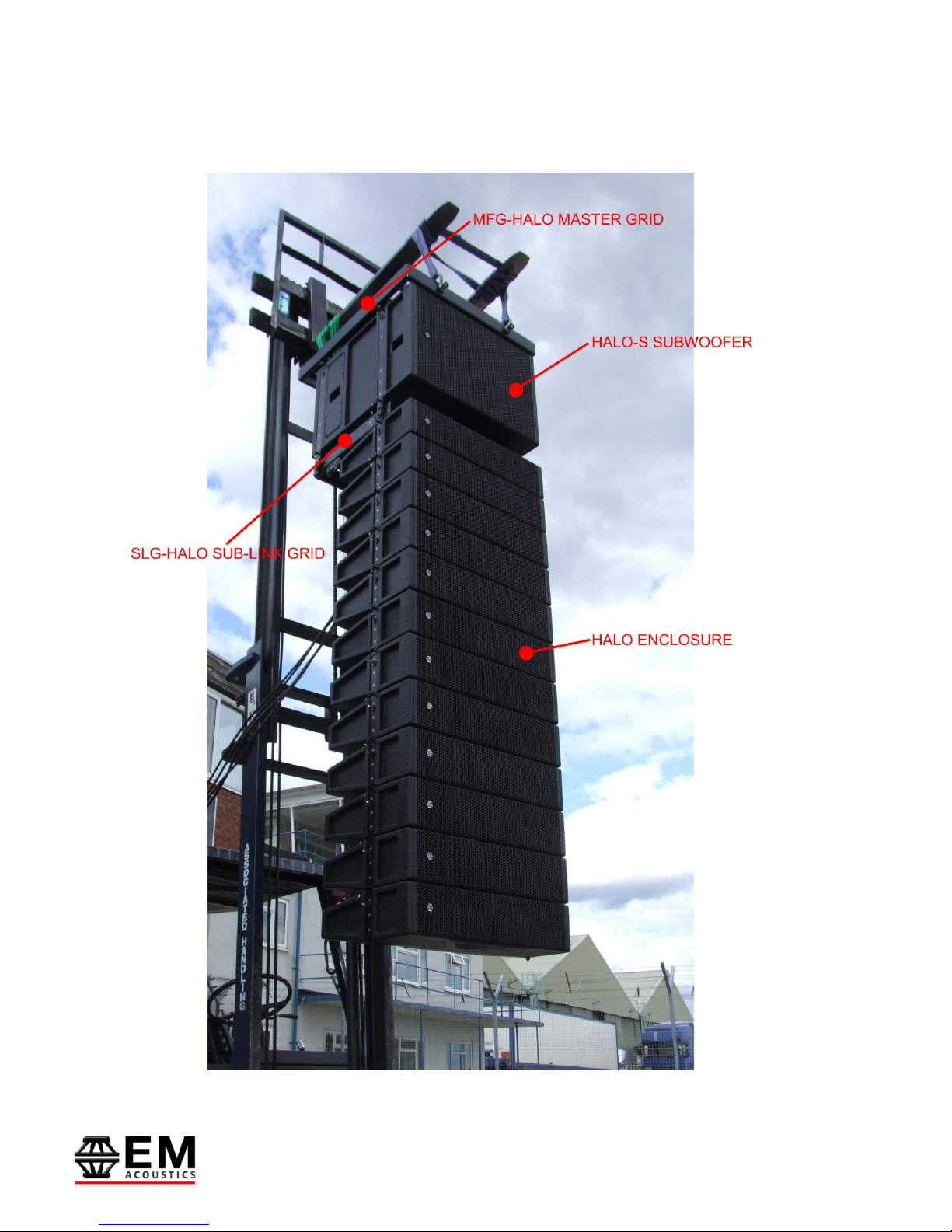
c) MFG-HALO master flying grid
The MFG-HALO grid is the main grid for the HALO system which can be used for
flying HALO enclosures on their own, but must be used to suspend HALO-S
subwoofers.
d) FG-HALO compact flying grid
The more compact FG-HALO grid can be used for flying HALO enclosures alone,
and is often the better choice where smaller numbers of HALO enclosures are
required and/or less down-angle for the array is required.
e) SLG-HALO sub-link flying grid
The SLG-HALO link grid must be used when assembling arrays including both
HALO and HALO-S enclosures. The SLG-HALO provides the mechanical interface
between the HALO-S subwoofer and the much shallower HALO enclosure.

Page 6of 39
HALO system User Manual
V2.2 August 2010
3.0 - Connections, Processor and Amplifier Selection
Connecting your loudspeakers
HALO enclosures are bi-amplified and use Neutrik SpeakonTM NL4 connectors - as such
they require 4-core cable to function correctly. Standard pin connections are LF/MF on
pins 1+/1- and HF on pins 2+/2-.
HALO-S subwoofers are wired pins 1+/1- with pins 2+/2- connected as a link-through.
Cable Selection
All cables add to the system impedance, and as such careful selection is required
depending on your amplifier setup and overall system impedance. Recommended
maximum cable lengths are given below:
Conductor Area Maximum Recommended Cable Length
4 ohms 8 ohms 16 ohms
1.0mm2 11m 22m 44m
1.5mm217m 34m 68m
2.0mm222m 44m 88m
2.5mm229m 58m 116m
4.0mm244m 88m 176m
6.0mm266m 132m 264m
IMPORTANT NOTE REGARDING SYSTEM IMPEDANCE
The HALO HF drive unit drops to 4 ohms across a reasonable portion of its operating
band. This can cause problems with some amplifiers when connecting the high frequency
sections of more than two HALO enclosures in parallel on an amplifier channel. However,
with the cable lengths involved in most line array usage scenarios, there is sufficient
impedance in the cable alone to bring the impedance up to a suitable level to prevent
amplifier problems. We would recommend when connecting 3 or more HALO high
frequency sections to a given amplifier channel, ensure cable runs of at least twenty
metres between the amplifier and the loudspeaker.
Amplifier Powers
We recommend the following power inputs for HALO enclosures:
HALO LF/MF (8 ohm impedance) 500W RMS, 1000W Program
HALO HF 375W RMS, 750W Program
HALO-S (4 ohm impedance) 1000W RMS, 2000W Program

Page 7of 39
HALO system User Manual
V2.2 August 2010
These amplifier powers can be scaled up –for example for running four HALO enclosures
in parallel from the same amplifier (ch 1 LF/MF, ch 2 HF) we would recommend an
amplifier capable of delivering 2500-3000 watts into a 2-ohm load.
NOTE:
A small amplifier working too hard is much more likely to damage your
loudspeakers than a large amplifier working well within its limits!

Page 8of 39
HALO system User Manual
V2.2 August 2010
Processor Selection & DSP Settings
The HALO system requires a suitable DSP loudspeaker management system to allow for
crossover points, system EQ and delay. EM Acoustics recommends either XTA 4-series
processors or Lake processing –either stand-alone units or incorporated into the
LabGruppen PLM series of amplifier products.
The DSP program detailed below is based around a 12-HALO system flown with a single
HALO-S subwoofer at the top of the array. Crossover points between HALO/HALO-S are
of course at the user‟s discretion, as are gain structures. We would strongly suggest that
the HALO settings (shown in bold below) are not altered from our recommended settings
as this can result in poor performance and/or damage to the HALO components. The
other two EQ points will vary depending on the size of the array used –for smaller arrays,
less HF boost and 202Hz cut will be required and vice-versa.
LMF/HMF
Gain: 0dB
Polarity: (+)
Delay: 0ms
HPF: 80.3Hz, 24dB/Oct Linkwitz-Riley
LPF: 1k78Hz, 48dB/Octave Linkwitz-Riley
EQ 1: 1k82Hz Q=9 -14dB
EQ 2: 516Hz Q=5 -9dB
EQ 3: 202Hz Q=1.5 -5dB
HF
Gain: +11dB
Polarity: (-)
Delay: 0.5417ms
HPF: 7k55Hz, 12dB/Oct Linkwitz-Riley
LPF: 20 kHz, 48dB/Octave Linkwitz-Riley
EQ 1: 1k78Hz Q=4 -4dB
EQ 2: 4k40Hz Q=2 -2dB
EQ 3: 9k33Hz Q=4 -4dB
EQ 4: 12kHz High Shelf Q=1 +8dB
HALO-S
Gain: +2dB
Polarity: (+)
Delay: 0.0ms
HPF: 35Hz, 24dB/Oct Butterworth
LPF: 95Hz, 24dB/Octave Linkwitz-Riley

Page 9of 39
HALO system User Manual
V2.2 August 2010
4.0 - Flying HALO systems
System Overview
The flying system for the HALO system has been specifically designed to be flexible,
intuitive and reliable. Please read this section of the user manual extremely carefully
as the rigging of loudspeakers is a very serious matter with potentially fatal consequences
should anything go wrong. If you are in ANY DOUBT WHATSOEVER, contact a
reputable rigging company or your local EM Acoustics representative.
IMPORTANT SAFETY CONSIDERATIONS
The HALO rigging system has been designed and constructed to a very high standard of
safety, and tested to demanding specifications. To ensure the highest standards of safety,
the following information on array assembly must be exactly followed and understood.
Only use EM Acoustics recommended rigging hardware and accessories, which are
specifically designed for the purpose. Do not use HALO flying hardware for any other
loudspeaker system –the components are specifically designed to work with the HALO
system and are not interchangeable with any other EM Acoustics loudspeaker product or
any other loudspeaker system. The use of HALO flying hardware with other
manufacturers‟ systems may compromise the safety standards and EM Acoustics, and its
parent company, are in no way liable for any loss, damage or injury caused by such
practice.
Do not modify or alter the HALO hardware or accessories, nor use them in any way other
than that described in this manual. Rigging components supplied as part of the HALO
system are in no way interchangeable and should not be used as such.
The component parts of the HALO rigging assembly should only be assembled in the
manner described in this manual, using the fasteners and fixings stated herein. The use
of fasteners and methods of assembly not described in this manual may result in an
unsafe assembly and as such EM Acoustics will not be responsible for any loss, damage or
injury caused by such practice. Welding, drilling or any other means of modifying any part
of the flying hardware or permanently fixing components to each other is strictly
forbidden.
Rigging assemblies must only be assembled using the appropriate parts and fixings as
described in this manual, explicitly following the assembly instructions given herein.
Rigging components must only be fixed to EM Acoustics HALO loudspeaker systems, using
the correct cabinet location points, assembly methods and fasteners specifically described
within this manual.

Page 10 of 39
HALO system User Manual
V2.2 August 2010
Walls, floors and ceilings must be capable of supporting the actual load placed upon them.
The rigging hardware must be safely and securely fixed to both the loudspeaker system
and the supporting structure.
When mounting components on walls, floors or ceilings ensure that all fixings and
fasteners used are of an appropriate size and load rating. Wall and ceiling claddings, and
the construction/composition of walls and ceilings also need to be taken into consideration
when determining if a given suspension method is safe.
Secondary Safeties
It is best practice to ensure that all loudspeakers flown in any given environment should
be provided with a second, independent and properly rated safety suspension point in
addition to the principle load bearing means of suspension. Steel wire ropes or steel
chains of an approved construction and load rating only may be used as secondary
safeties. Plastic covered steel chains may not be used as secondary safeties under any
circumstances. Also ensure that all local and national laws are complied with when
determining your primary and secondary suspension points.
Safety Inspections
Carefully inspect all flying system components prior to use for defects or signs of damage
prior to assembling a HALO array. If any components damaged or you suspect them to
be damaged, DO NOT USE THEM.
Regular scheduled tests –which are much more rigorous than visual inspections –of all
rigging components must also be carried out. Safety legislation, and test/inspection
requirements, will vary from country to country and as such it is the user‟s responsibility to
ensure that local regulations are adhered to. In most cases, annual independent tests &
inspections carried out by a suitably approved and qualified inspector will be required.
EM Acoustics recommends detailed logbooks be kept of all inspections and load tests to
ensure an accurate record is kept of the testing for each EM Acoustics rigging accessory.
When flying any loudspeaker system, always wear protective headwear, footwear and eye
protection in accordance with local regulations.
The rigging of a flown loudspeaker system may be dangerous if not undertaken
by a suitably experienced and qualified rigger. Installation & fixing of all
hanging points should only be carried out by a professional rigger in
accordance with local legislation as well as the rules of the venue. The house
rigger and/or venue manager must always be consulted.

Page 11 of 39
HALO system User Manual
V2.2 August 2010
Safety Factors
The HALO system is designed to work within the following safety factors:
MFG-HALO –Safety factor of 4
22 x HALO enclosure
OR
20 x HALO enclosure
1 x SLG-HALO grid
1 x HALO-S enclosure
OR
16 x HALO enclosure
1 x SLG-HALO grid
2 x HALO-S enclosures
MFG-HALO –Safety factor of 6
16 x HALO enclosure
OR
12 x HALO enclosure
1 x SLG-HALO grid
1 x HALO-S enclosure
SLG-HALO –safety factor of 4
20 x HALO enclosure
SLG-HALO –safety factor of 6
14 x HALO enclosure
SLG-HALO –safety factor of 8
10 x HALO enclosure
Page 12 of 39
HALO system User Manual
V2.2 August 2010
4.1 - Assembling Flown Arrays with Subwoofers

Page 13 of 39
HALO system User Manual
V2.2 August 2010
This section describes setting up of a HALO array similar to that shown above, comprising
HALO-S subwoofers and HALO elements.
Step One –MFG-HALO grid preparation
The drop links for the MFG-HALO grid are stored inside the chassis of the flying grid for
transport. The first step is to prepare these links ready to fly the system. The MFG-HALO
grid has five link positions:
Front Drop Links –these are removable and are used for flying both HALO-S and
HALO enclosures. Two different sets of front links are provided –larger links for
HALO-S subwoofers and smaller links for HALO enclosures. The alternate links are
stored in recesses on the sides of the MFG grid as shown below.
Rear Drop Links –these are fixed and are only used for flying HALO-S Subwoofers.
Central Splay Link –this is fixed and is only used for flying HALO enclosures.
Firstly, ensure you have the correct front drop links in place to fly your chosen system. In
this example, we are flying a HALO-S subwoofer at the top of the array and as such we
want the larger of the two links as shown in the image below.
Page 14 of 39
HALO system User Manual
V2.2 August 2010
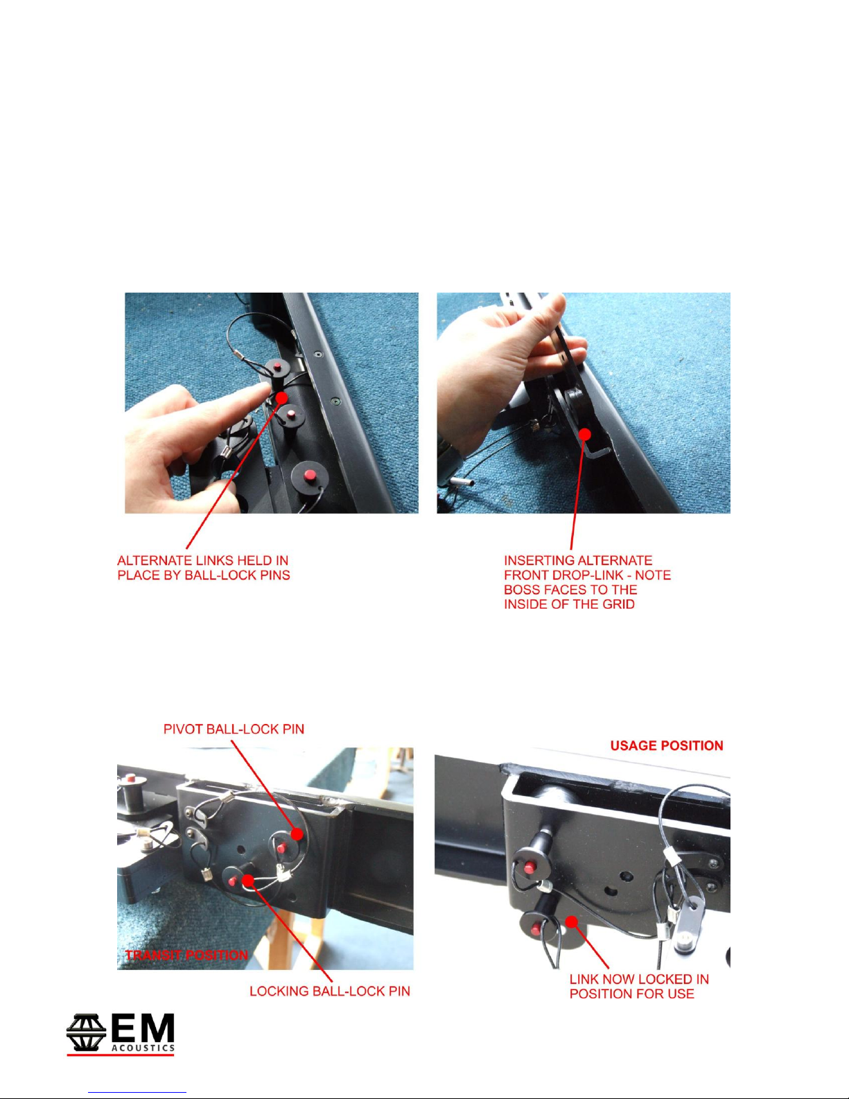
Should you need to change the links, the alternative links are stored on the sides of the
MFG grid and are held in place by ball-lock pins. Release the pins as shown below and
remove the alternate links.
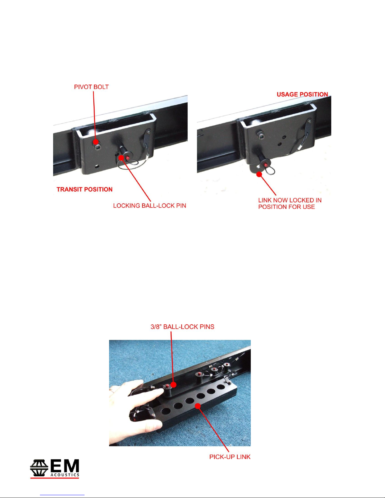
When fitting the new links, the link pivots on the upper ball-lock pin and is locked in place
for use by the lower pin. Ensure when fitting the new link into the grid that the thicker
steel boss faces to the inside of the MFG-HALO grid. It is easier to fit the new links from
the bottom of the grid.
Once you have established the appropriate front drop-links, move the links into the usage
position by removing the lower ball-lock pin which will allow the link to swing freely, and
then replace the ball-lock pin to lock the link in position.
Page 15 of 39
HALO system User Manual
V2.2 August 2010
This process should now be repeated for the rear links –however the rear links are
pivoted permanently on a bolt. As such, simply release the ball-lock pin to allow the link
to sit into the usage position, replace the ball-lock pin and the link is now ready for use.
IMPORTANT NOTE:
For both front & rear links, the locking ball-lock pin MUST be in position prior to
attempting to fly the system.
Step Two –Selecting & fitting pick-up links
The MFG-HALO grid provides two means of attaching the grid to your chosen primary
mounting point. The first, and most common is by using the movable pick-up links which
allow for both single point and dual point pick-up. These links are stored for transit on the
side of the MFG grid and are secured in place by two 3/8” ball-lock pins.

Page 16 of 39
HALO system User Manual
V2.2 August 2010
Fit the links into the groove down the central spine on the MFG grid, and slide the link
along to the desired position. The different pairs of holes for the 3/8” pins along the
length of the spine allow for a variety of different positions for the pick-up link, with
complete flexibility. Repeat this process for the second pick-up link.
IMPORTANT NOTE:
Both 3/8” ball-lock pins MUST be secured on each pick-up link being used.
3.25 ton bow shackles can then be used to select the appropriate connection hole in each
pick-up link as shown above.
The second means of securing pick-up points on the MFG-HALO grid is to use the four
holes located front & rear on the grid to attach 3.25 ton bow shackles, and bridle between
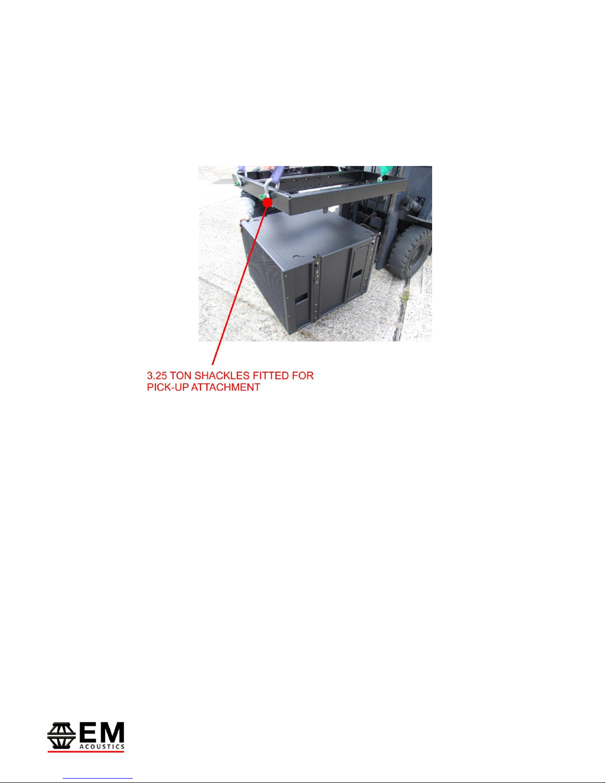
Page 17 of 39
HALO system User Manual
V2.2 August 2010
them. An example of this procedure is shown in the photo below. These additional points
can also be used to attach secondary safeties to the system.
Ensure with whichever method you use for pick-up, that you have the MFG-HALO grid
facing the right direction –indicated by the “FRONT” arrows on each side of the grid.
Step 3 –Attaching HALO-S subwoofer enclosures
Once you have your MFG-HALO flying grid prepared, and suspended from your primary
load-bearing point, you are ready to assemble your HALO array. In this example we are
using HALO-S subwoofers, therefore this is the first part of the array to be assembled.
Position your HALO-S enclosure below the grid as shown in the photo above. Release the
four ¼” ball-lock pins on the rigging system, and lower the grid into position –taking care
to ensure that all four drop-links on the MFG-HALO grid locate within the rigging hardware
on the cabinet. Once the grid is in position, secure the grid to the enclosure using the
four ball-lock pins on the HALO-S enclosure.

Page 18 of 39
HALO system User Manual
V2.2 August 2010
Raise the MFG-HALO grid up, lifting the HALO-S subwoofer with it. Once clear of the
ground, undo the four countersunk socket-head bolts which secure the base board to the
HALO-S. Remove the board and retain for array disassembly.
If adding a second subwoofer, repeat the procedure above. If you are only using one
subwoofer, proceed to step 4 below.
Step 4 –Attaching the SLG-HALO sub-link grid
The SLG-HALO grid provides the mechanical link between the HALO-S and the much
shallower HALO enclosure. It is specifically designed to give the same flexibility to the
HALO array is if you were flying straight from a MFG-HALO grid.

Page 19 of 39
HALO system User Manual
V2.2 August 2010
Firstly, ensure you have the SLG-HALO grid in the correct orientation by observing the
“FRONT” labels on the sides of the grid. Release the four ¼” ball-lock pins on the corners
of the grid, to allow the bottom of the HALO-S rigging hardware to mate with the grid.
Offer the grid up to the bottom of the HALO-S (this is possible with one person but is
much easier with two!) and once in position, secure the grid to the bottom of the HALO-S
using the four ball-lock pins secured to the grid itself.
The last step prior to attaching your HALO enclosures is to set the desired splay angle for
the first HALO enclosure in the array. For this, you need the central splay link on the SLG-
HALO grid. This link pivots on a bolt and is secured in the transit position by a ball-lock
pin. Release this pin and rotate the link to the desired position –either 0 degrees (top
HALO enclosure is parallel to the grid) or 5 degrees (top enclosure is angled down 5
degrees relative to the SLG grid). Secure in position with the ball-lock pin as shown
below.

Page 20 of 39
HALO system User Manual
V2.2 August 2010
Step 5 –Attaching HALO enclosures
This procedure is made much quicker by the use of flightcases or the WB-HALO
wheelboard (shown below) as groups of HALO enclosures can be pre-assembled, resulting
in much faster array assembly.
As shown below, position your HALO enclosures beneath the array. Release the ball-lock
pins on both sides of the front rigging, and also the lock position on the rear splay rigging.
Table of contents
Other EM Acoustics Speakers System manuals


