EM Microelectronic EMDVK8502 User manual

QUICK START ƖEMDVK8502
Copyright 2016, EM Microelectronic-Marin SA
EMDVK8502-MN02, Version 1.0, 5-Jul-16
1
www.emmicroelectronic.com
420005-A01, 3.0
EMDVK8502 QUICK START GUIDE
AC/DC plug +5V
Additional +5V supply
USB cable
PC to Base board cable
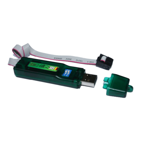
USB dongle
Install Setup
USB stick
Application board
Application PCB
Base board
PC Control board
Daughter board
8502 board
Solar cell
Your EMDVK8502 Development Kit contains:
ƖEMDVK8500 Base Board –8502 Daughter Board –Application Board
ƖUSB Cable
ƖPower-supply
ƖUSB Dongle containing EM8500 DevExplorer software installation setup
ƖSolar cell
Full documentation for EMDVK8500 and DevExplorer is available on EM website (EMDVK8500 user guide)
http://www.emmicroelectronic.com/emdownloads/EM8500/doc/emdvk8500_user_guide.pdf
This quick start document guides you through the set-up of your development hardware kit, software and demo.
EM MICROELECTRONIC - MARIN SA

QUICK START ƖEMDVK8502
Copyright 2016, EM Microelectronic-Marin SA
EMDVK8502-MN02, Version 1.0, 5-Jul-16
2
www.emmicroelectronic.com
420005-A01, 3.0
1 INSTALL THE EM8500 DEVEXPLORER SOFTWARE TOOL FROM THE USB DONGLE
ƖConnect the USB memory stick on the Base board (USB MEM connector)
ƖConnect the Base board (USB Host) to the PC using the USB cable.
ƖSkip and close the installation driver window that may pop-up.
ƖOpen an explorer window.
ƖClick on the relevant USB stick drive.(EM8500 DevKit)
ƖDouble click on the EM8500 DevExplorer setup executable file.
This setup will guide you through the installation process.
Any additional questions? Please refer to the EMDVK8500 User Guide
2 CHECK THE DAUGHTER BOARD CONFIGURATION
ƖPlace the jumpers as shown below
J105 - LTS_CAP
Jumper to connect
LTS supercap
J102 - LTS_DISCONN
Jumper to c onnect
LTS pin
J103 - STS_DISCONN
Jumper to c onnec t
STS pin
3 CONNECT THE SOLAR CELL TO THE HRV DAUGHTER BOARD SCREW TERMINAL
RED BLACK
HRV +
HRV -
SOLAR CELL

QUICK START ƖEMDVK8502
Copyright 2016, EM Microelectronic-Marin SA
EMDVK8502-MN02, Version 1.0, 5-Jul-16
3
www.emmicroelectronic.com
420005-A01, 3.0
4 BUILD AND CONNECT THE SYSTEM TO THE PC
ƖPlug the three boards together
ƖConnect the USB cable
ƖConnect the power-supply.
APP2 APP1
AC/DC
Plug
+5V
USB
PC
5 LAUNCH THE DEVEXPLORER SOFTWARE
ƖUse the Start Menu shortcut EM8500 DevExplorer to launch the software.
EM8500 DevExplorer shortcut

QUICK START ƖEMDVK8502
Copyright 2016, EM Microelectronic-Marin SA
EMDVK8502-MN02, Version 1.0, 5-Jul-16
4
www.emmicroelectronic.com
420005-A01, 3.0
6 RUN THE DEMO
A default application demo is available on EMDVK8502.
ƖSelect the Measure window
ƖCheck that all the switches and selectors are set as shown below
CLOSED
OPEN
APPLICATION
OPEN
OPEN
CLOSED
DON’T CARE
ƖClick on the A/D measurement button to observe measured voltages.
Select Measure
window
Start A/D
measurement

QUICK START ƖEMDVK8502
Copyright 2016, EM Microelectronic-Marin SA
EMDVK8502-MN02, Version 1.0, 5-Jul-16
5
www.emmicroelectronic.com
420005-A01, 3.0
ƖSelect the Visualize window
ƖClick on the Graph 1 and/or Graph 2 “Click to add graphs” buttons to add the signals or thresholds that you
want to observe in your graphical window
Click to add
graph
Select Visualize
window

QUICK START ƖEMDVK8502
Copyright 2016, EM Microelectronic-Marin SA
EMDVK8502-MN02, Version 1.0, 5-Jul-16
6
www.emmicroelectronic.com
420005-A01, 3.0
ƖThe EM8500 DevExplorer Graph viewer tool allows you to navigate within the waveforms
Mouse viewer tool
Zoom-In : Mark top-left to bottom right
Zoom-Out : Mark bottom-right to top left
Move: Hold down right mouse button
Select : Click legend to select channels
.
EM Microelectronic-Marin SA (“EM”) makes no warranties for the use of EM products, other than those expressly contained in EM's
applicable General Terms of Sale, located at http://www.emmicroelectronic.com. EM assumes no responsibility for any errors which may
have crept into this document, reserves the right to change devices or specifications detailed herein at any time without notice, and does not
make any commitment to update the information contained herein.
No licenses to patents or other intellectual property rights of EM are granted in connection with the sale of EM products, neither expressly
nor implicitly.
In respect of the intended use of EM products by customer, customer is solely responsible for observing existing patents and other
intellectual property rights of third parties and for obtaining, as the case may be, the necessary licenses.
Important note: The use of EM products as components in medical devices and/or medical applications, including but not limited
to, safety and life supporting systems, where malfunction of such EM products might result in damage to and/or injury or death of
persons is expressly prohibited, as EM products are neither destined nor qualified for use as components in such medical devices
and/or medical applications. The prohibited use of EM products in such medical devices and/or medical applications is exclusively
at the risk of the customer
Table of contents
