Embux EBC2A0 User manual
1
EBC2A0
2.5’’ SBC with Freescale i.MX6 Processor
ARM ® Cortex A9 Architecture
User Manual
Ver. 1st

2
Copyright
Copyright © 2015 EMBUX Technology Co., Ltd., All rights reserved.
EMBUX Technology Co., Ltd. reserves the right to make improvements in the
products described in this manual at any time without notice. No part of this
manual may be reproduced, copied, translated or transmitted in any form or by
any means without prior written permission of EMBUX Technology Co., Ltd.
Trademark
The EMBUX logo is a registered trademark of EMBUX Technology Co., Ltd.
All other trademarks or registered marks in this manual belong to their respective
manufacturers.
Disclaimer
Information in this document is subject to change without notice and does not
represent a commitment on the part of EMBUX.
EMBUX provides this document as is, without warranty of any kind, either
expressed or implied, including, but not limited to, its particular purpose. EMBUX
reserves the right to make improvements and/or changes to this manual, or to
the products and/or the programs described in this manual, at any time.
Information provided in this manual is intended to be accurate and reliable.
However, EMBUX Technology Co., Ltd. assumes no responsibility for its use, nor
for any infringements of the rights of third parties, which may result from its use.
This product might include unintentional technical or typographical errors.
Changes are periodically made to the information herein to correct such errors,
and these changes are incorporated into new editions of the publication.

3
Declaration of Conformity
FCC Class B
Note: this device has been tested and found to comply with the limits for a Class
B digital device, pursuant to part 15 of the FCC Rules. These limits are designed
to provide reasonable protection against harmful interference in a residential
installation. This device generates, uses and can radiate radio frequency energy
and, if not installed and used in accordance with the instructions, may cause
harmful interference to radio communication. However, there is no guarantee
that interference will not occur in a particular in a particular installation. If this
device does cause harmful interference to radio or television reception, which
can be determined by turning the device off and on, the user is encouraged to try
to correct the interference by one or more of following measures:
Reorient or relocate the receiving antenna
Increase the separation between the device and receiver
Connect the device into an outlet on a circuit different from that to which
receiver is connected
Consult the dealer or an experienced radio/TV technician for help
CE Marking
This device has passed the CE test for environmental specifications when shielded
cables are used for external wiring. We recommend the use of shielded cables.
This device has passed the CE test for environmental specifications. Test
conditions for passing included the equipment being operated within an
industrial enclosure. In order to protect the product from being damaged by ESD
(Electrostatic Discharge) and EMI leakage, we strongly recommend the use of CE-
compliant industrial enclosure products.

4
Document Amendment History
Revision
Date
Remark
1st
May 2015
Initial released
2nd
May 2015
Modify RS-232 (JCOM1) description from full
pins to 2 pins function

5
Table of Contents
1. Product Overview .............................................................................................. 8
1.1. Introduction ....................................................................................... 8
1.2. Specification....................................................................................... 8
1.3. Block Diagram .................................................................................. 10
2. Hardware User Guide ...................................................................................... 12
2.1. Jumper and Connector Locations ..................................................... 12
2.2. Jumper ............................................................................................. 13
2.2.1. Jumper Description................................................................... 13
2.2.2. Jumper List ............................................................................... 13
2.2.3. Jumper Setting.......................................................................... 13
2.3. Connector ........................................................................................ 14
2.3.1. Connector List........................................................................... 14
2.3.2. Connector Setting..................................................................... 14
2.3.2.1. RS-485 .............................................................................. 14
2.3.2.2. JCOM1.............................................................................. 15
2.3.2.3. JDC in................................................................................ 15
2.3.2.4. JEMBUX ............................................................................ 15
2.3.2.5. JFP .................................................................................... 16
2.3.2.6. JI2C................................................................................... 16
2.3.2.7. JLVDS ................................................................................ 16
2.3.2.8. JMISC................................................................................ 16
2.3.2.9. JRS-485 ............................................................................. 17
2.3.2.10. JSIM................................................................................ 17
2.4. Mechanism ...................................................................................... 17
2.4.1. Board Dimension ...................................................................... 17
3. Software User Guide........................................................................................ 19
3.1. Introduction ..................................................................................... 19
3.2. Setup Build Environment .................................................................. 19
3.2.1. Installing and build ................................................................... 19
3.2.2. Download source code and checkout the latest version............ 20
3.2.3. Build and Flashing the SD card .................................................. 20
3.3. Create SD/MMC Card using Linux Host ............................................. 21
3.3.1. Requirements ........................................................................... 21
3.3.2. Copying the Boot loader Image................................................. 21
3.3.3. Copying the Kernel Image......................................................... 22
3.3.4. Copying the Root File System (rootfs) ....................................... 22

6
3.4. Applications and Testing ................................................................... 23
3.4.1. Ethernet Test ............................................................................ 23
3.4.2. USB........................................................................................... 24
3.4.3. SD............................................................................................. 24
3.4.4. I2C............................................................................................ 24
3.5. Create a Virtual Machine Environment ............................................. 25
3.5.1. Introduction ............................................................................. 25
3.5.2. Setting up work environment ................................................... 25
4. System Recovery.............................................................................................. 29
4.1. Download the SD image ................................................................... 29
4.2. Write an SD/MMC Card using Linux (Ubuntu)................................... 29
4.3. Write an SD/MMC Card using Windows ........................................... 30
4.3.1. Introduction ............................................................................. 30
4.3.2. Preparations ............................................................................. 30
4.3.3. Create SD-Card ......................................................................... 30
4.4. Write an SD/MMC Card using MAC OS X .......................................... 31
4.4.1. graphical interface .................................................................... 31
4.4.2. Command line .......................................................................... 32
4.4.3. Alternative method................................................................... 32

7
Chapter 1
Product Overview
This chapter provides background
Information of SBC.
8
1. Product Overview
1.1. Introduction
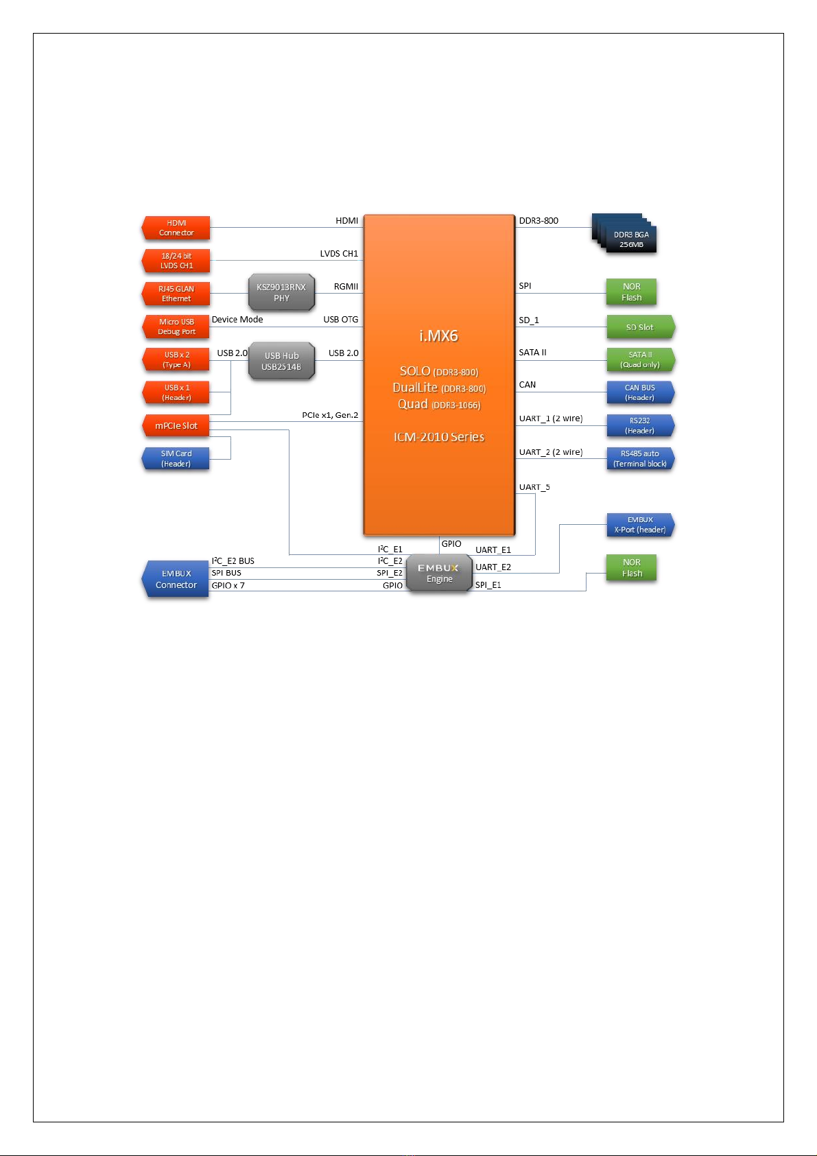
ICM-2010 is a 2.5’’ SBC (Single Board Computer) with ARM Cortex-A9
Freescale i.MX6 DualLite (Solo / Quad by request) 1GHz processor and ARM
Cortex™-M0 32-bit RISC core (MCU). The ICM-2010 can support 1GB DDR3 and
8MB onboard NOR Flash, LVDS, HDMI display, 1 Gigabit LAN with IEEE 1588, 3 USB
2.0, 1 micro USB type B (device mode only), 1 RS-232, 1 RS-485, 1 CAN, 1 SATA II,
1 Full size mini PCIe, 1 SD and SIM (header).
Integrated unique dual hardware structure and RTOS (real time operating
system) design, ICM-2010 has outstanding crash free protection on both
hardware reliability and software stability. With the special features, ICM-2010 is
a perfect device to meet customers’ versatile needs.
The ICM-2010 focuses on single application and it provides high
performance and low power consumption from its ARM ® Cortex A9 architecture
which is ready-to-run, compact, and easy-to-expand. With flexible I/O interfaces
and complete hardware and software solutions, ICM-2010 is a fast time-to-
market platform for customers to develop their applications and products easily.
1.2. Specification
System Hardware - CPU
CPU
Freescale i.MX6 Cortex-A9 DualLite (Solo/Quad sku by request)
Memory
Technology
DDR3-800 (800/1066 MHz for Solo/Quad by request)
Capacity
Onboard 1GB (512MB/1GB for Solo/Quad by request)
Flash
8MB NOR Flash
Graphic
HDMI
1 x HDMI connector
LVDS
1 x 18/24 bit LVDS header (2x10 1.25mm Hirose DF13 series
compatible)
Watchdog Timer
1~256 level (second)
RTC
EPSON RX8010SJ RTC chip
Indicator
LED
1 x configurable indicator controlled by MCU
1 x configurable indicator controlled by i.MX6
I/O
LAN
1 x Micrel KSZ9031RNX Gigabit Ethernet
USB
1 x USB (miscellaneous header)
1 x 2 ports USB (double-deck connector)
USB OTG
1 x micro USB type B (device mode only)
Serial Port
1 x RS-232 header (2x5 2.0mm pin header)
1 x RS-485 (1x2 3.5mm terminal block)
CAN
1 CAN bus header (miscellaneous header)

9
GPIO
9 x GPIO via MCU
Button
1 x power-on button
2 x configurable buttons
Expansion
Full size
mini PCIe
x 1
SATA
1 x SATA II port (Quad model only)
SD socket
x 1
SIM slot
1 x SIM card header
System Hardware - MCU
MCU
STM32F051R8T6
Memory
Flash
8MB NOR Flash
I/O
EMBUX X Port
1 x EMBUX X Port (miscellaneous header)
I2C
1 x I2C interface (2x10 1.25mm Hirose DF13 series compatible, shared
with SPI and GPIO) for Mainboard MCU to accessory (i.e OLED module)
connection purpose
SPI
1 x SPI interface (2x10 1.25mm Hirose DF13 series compatible, shared
with I2C and GPIO) for Mainboard MCU to accessory (i.e OLED module)
connection purpose
GPIO
7-bit GPIO (2x10 1.25mm Hirose DF13 series compatible, shared with
SPI and I2C) for Mainboard MCU to accessory (i.e OLED module)
connection purpose
System Software
Operation System
Linux
Embedded Linux 3.0.35
Android
Jelly Bean 4.3
Environment & Mechanism
Temperature
Operation
temperature
0~60°C
Humidity
Operation
humidity
5%~95% Relative Humidity, non-condensing
Mechanical
Dimension
PICO-ITX (100mm X 72mm)
Power
DC-input
5V (4.75V~5.25V)
Control
Power on by DC attached or via power button.
Consumption
~3W
10
1.3. Block Diagram

11
Chapter 2
Hardware User Guide
This chapter introduces the startup procedures of ICM-2010,
including jumper setting and device integration. It also introduces
the setting of switches, indicators and also shows the mechanical
drawings. Be sure to real all safety precautions before you begin
installation procedure.

12
2. Hardware User Guide
2.1. Jumper and Connector Locations
Top side:
Rear side:
JFP
JCOM1
JMISC
JLVDS
JI2C
MPCIE
JSIM
SATA
JEMBUX
Connector
JDC in
DC in
USB
LAN
RS-485
HDMI
JRS-485
13
2.2. Jumper
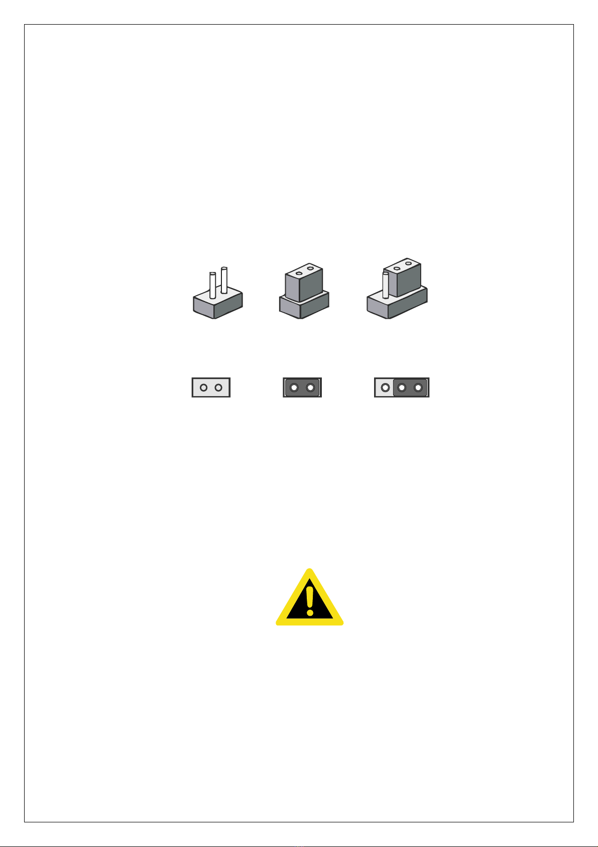
2.2.1. Jumper Description
Cards can configured by setting jumpers. A jumper is a metal bridge used to close
an electric circuit. It consists of two metal pins and a small metal clip (often
protected by a plastic cover) that slides over the pins to connect them. To close a
jumper, you connect the pins with the clip. To open a jumper, you remove the clip.
Sometimes a jumper will have three pins, labeled 1, 2 and 3. In this case you
would connect either pins 1 and 2 or 2 and 3.
The jumper settings are schematically depicted in this manual as follows.
A pair of needle-nose pliers may be helpful when working with jumpers. If you
have any doubts about the best hardware configuration for your application,
contact your local distributor or sales representative before you make any
changes.
Generally, you simply need a standard cable to make most connections.
Warning!
To avoid damaging the computer, always turn off the power supply
before setting jumpers.
2.2.2. Jumper List
2.2.3. Jumper Setting
123
12
12
1 2 31212

14
2.3. Connector
2.3.1. Connector List
DC in
DC power input connector
DC power jack
RS-485
RS-485 connector
2 x 1 connector, pitch 3.5mm
HDMI
HDMI connector
JCOM1
RS-232 pin header
5 x 2 header, pitch 2.0mm
JDC in
Power input pin header
2 x 1 connector, pitch 4.2mm
JEMBUX
Proprietary connector
DF13-20DP-1-25V
JFP
Front panel connector
5 x 2 header, pitch 2.0mm
JI2C
I2C connector
4 x 1 header, pitch 2.54mm
JLVDS
LVDS connector
DF13-20DP-1-25V
JMISC
Miscellaneous connector
5 x 2 header, pitch 2.0mm
JRS-485
Reserved for X-Port connect
2 x 1 header, pitch 2.0mm
JSIM
SIM connector + SATA PWR
4 x 2 header, pitch 2.54mm
LAN
Ethernet connector
RJ-45
MPCIE
Mini PCI Express connector
SATA
SATA connector
USB
USB connector
USB Type A
2.3.2. Connector Setting
2.3.2.1. RS-485
Description
Pin
RS-485-
1
RS-485+
2

15
2.3.2.2. JCOM1
Description
Pin
Pin
Description
N/C
1
2
RS-232_RX
RS-232_TX
3
4
N/C
GND
5
6
N/C
N/C
7
8
N/C
N/C
9
10
N/C
2.3.2.3. JDC in
Description
Pin
GND
1
5V
2
2.3.2.4. JEMBUX
Description
Pin
Pin
Description
3.3V
2
1
5V
3.3V
4
3
5V
GPIO0
6
5
GND
GPIO1
8
7
MCU_SS
GPIO2
10
9
MCU_CLK
GPIO3
12
11
MCU_MOSI
GPIO4
14
13
MCU_MISO
GPIO5
16
15
GND
GPIO6
18
17
I2C CLK
N/C
20
19
I2C DAT
Remark:
GPIO pin control by MCU (level 3.3V)
MCU_SS: SPI Slave Select (active low, output from master)
MCU_CLK: SPI Serial Clock (output from master)
MCU_MOSI: SPI Master Output, Slave Input (output from master)
MCU_MISO: Master Input, Slave Output (output from slave)
16
2.3.2.5. JFP
Description
Pin
Pin
Description
5V
1
2
LED control by MCU
5V
3
4
LED control by CPU
CPU power on
5
6
GND
GPIO7
7
8
GND
GPIO8
9
10
GND
Remark:
GPIO pin control by MCU (level 3.3V)
2.3.2.6. JI2C
Description
Pin
3.3V
1
I2C_SCL
2
I2C_SDA
3
GND
4
2.3.2.7. JLVDS
Description
Pin
Pin
Description
3.3V
2
1
5V
3.3V
4
3
5V
Backlight EN (3.3V)
6
5
LVDS0_CLK-
Backlight CTL (3.3V)
8
7
LVDS0_CLK+
GND
10
9
GND
LVDS0_TX1-
12
11
LVDS0_TX0-
LVDS0_TX1+
14
13
LVDS0_TX0+
GND
16
15
GND
LVDS0_TX3-
18
17
LVDS0_TX2-
LVDS0_TX3+
20
19
LVDS0_TX2+
2.3.2.8. JMISC
Description
Pin
Pin
Description
EMBUX X-Port RS-485 TX-
1
2
5V
EMBUX X-Port RS-485 TX+
3
4
USB D-
GND
5
6
USB D+
CAN_H
7
8
GND
CAN_L
9
10
GND
17
2.3.2.9. JRS-485
Description
Pin
RS-485TX-
1
RS-485TX+
2
2.3.2.10. JSIM
Description
Pin
Pin
Description
PCIe_UIM_PWR
1
2
PCIe_UIM_RST
PCIe_UIM_CLK
3
4
GND
PCIe_UIM_VPP
5
6
PCIe_UIM_DATA
5V
7
8
GND
Remark:
UIM: User Identity Module (UIM) Signals
UIM_VPP: Variable supply voltage (e.g., programming voltage) for class A devices. This signal is reserved for
future use for devices of other classes. Compliant to the ISO/IEC 7816-3 specification (VPP).
5V on pin 7 is reserved for SATA power
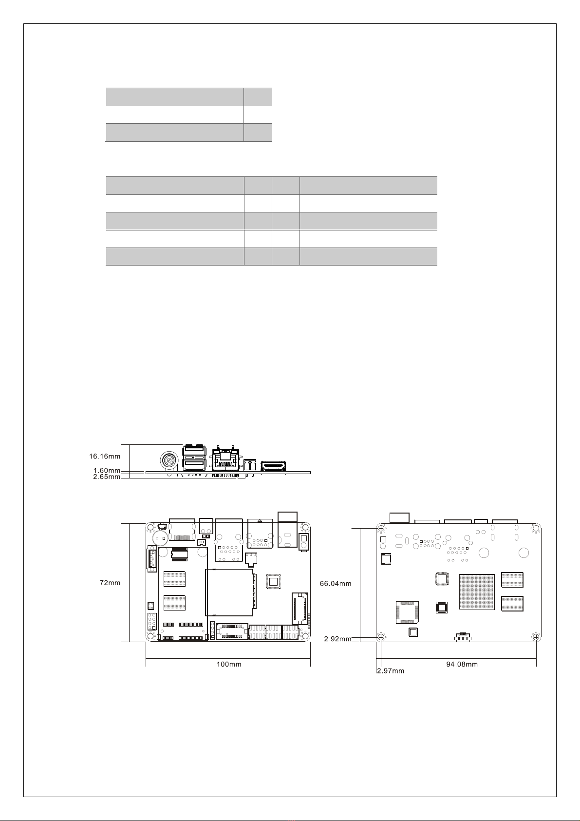
2.4. Mechanism
2.4.1. Board Dimension

18
Chapter 3
Software User Guide
This chapter details the Linux operation on ICM-2010.

19
3. Software User Guide
3.1. Introduction
This chapter details the Linux operation on ICM-2010 platform. This platform is an
embedded system with Linux kernel 3.0.35. It contains all system-required shell
commands and drivers ready. You can evaluate and develop under Ubuntu 12.04
LTS environment.
There are three major boot components for Linux, “u-boot.bin”, “uImage” and “root
file system”. The “u-boot.bin” is for initializing peripheral hardware parameters; the
“uIm- age” is the Linux kernel image and the “File System” is for Linux O.S. used.
It will not be able to boot into Linux environment successfully if one of above three
files is missing from booting media (in ICM-2010, we use SD/MMC card)
3.2. Setup Build Environment
This section explains how to set up the build environment, install and build, and set
up the host environment.
Note: If you need, more detailed instructions can be found at
L3.0.35_4.1.0_LINUX_DOCS in the file Setting_Up_LTIB_Host.pdf
(https://cache.freescale.com/secured/32bit/doc/support_info/L3.0.35_4.1.0_docs.tar.
gz?__gda__=1428423300_12712125f6c749dde454e0f5d9b338d5&fileExt=.gz)
3.2.1. Installing and build
Follow the steps below to preparing the build environment. Entering the command
without “$”.
# 0.1 pre-install
$ sudo apt-get install git u-boot-tools lzop
# 0.2 Cross Compiler As a result of the first two points, we now recommend these
simple steps to install a cross-compiler:
$ sudo apt-get install gcc-arm-linux-gnueabihf

20
# check gcc version
$ arm-linux-gnueabihf-gcc -v
# 0.3 add export to .bashrc
export ARCH=arm
export CROSS_COMPILE=arm-linux-gnueabihf-
3.2.2. Download source code and checkout the latest version
# 1.1 u-boot source (u-boot-2009)
git clone https://github.com/embux/u-boot-imx.git u-boot-imx_2009
cd u-boot-imx_2009
git checkout imx_2009_ebx
# 1.2 Kernel source (imx_3.0.35)
$ git clone https://github.com/embux/linux-imx6.git
$ cd linux-imx6.git
$ git checkout imx_3.0.35_1.0.0_ebx
3.2.3. Build and Flashing the SD card
- u-boot
$make distclean
$make mx6dl_sabresd_config
$make
$ sudo dd if=u-boot.bin of=/dev/sdb bs=512 seek=2 skip=2 conv=fsync
- Kernel build and flash to SD Card (sdb, mounted /mnt)
$make clean
$make imx6_defconfig
$make -j4 uImage
Table of contents
Other Embux Motherboard manuals


