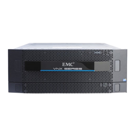
EMC2 VNXe3150 Owner's manual

EMC® VNXe™Series
VNXe3150™
Hardware Information Guide
P/N 300-013-604
REV 02

EMC VNXe3150 Hardware Information Guide
2
Copyright © 2016 EMC Corporation. All rights reserved. Published in the USA.
Published March, 2016
EMC believes the information in this publication is accurate as of its publication date. The information is subject to change without
notice.
The information in this publication is provided as is. EMC Corporation makes no representations or warranties of any kind with respect
to the information in this publication, and specifically disclaims implied warranties of merchantability or fitness for a particular
purpose. Use, copying, and distribution of any EMC software described in this publication requires an applicable software license.
EMC2, EMC, and the EMC logo are registered trademarks or trademarks of EMC Corporation in the United States and other countries.
All other trademarks used herein are the property of their respective owners.
For the most up-to-date regulatory document for your product line, go to the technical documentation and advisories section on the
EMC online support website.

EMC VNXe3150 Hardware Information Guide 3
CONTENTS
Chapter 1 Preface
Chapter 2 Overview
VNXe3150 platform....................................................................................... 9
Front view ............................................................................................. 10
Rear view .............................................................................................. 10
Hardware features................................................................................. 11
System component description................................................................... 13
Disk processor enclosure ...................................................................... 13
Front view ............................................................................................. 15
Rear view .............................................................................................. 17
Cache Protection Module ...................................................................... 34
Disk-array enclosure ............................................................................. 35
Specifications ............................................................................................. 52

4 EMC VNXe3150 Hardware Information Guide
Contents

EMC VNXe3150 Hardware Information Guide 5
Preface
As part of an effort to improve and enhance the performance and capabilities of its
product line, EMC from time to time releases revisions of its hardware and software.
Therefore, some functions described in this
document
might not be supported by all
revisions of the software or hardware currently in use. For the most up-to-date information
on product features, refer to your product release notes.
If a product does not function properly or does not function as described in this
document
, please contact your EMC representative.
About this book
This guide describes the EMC®VNXe3150™. The VNXe3150 platform supports a disk
processor enclosure (DPE) with one to two storage processors (SPs).
In the single SP configuration, a Cache Protection Module is provided. This Cache
Protection Module is used in the event of an outage. The data in the VNXe3150 platform
write cache is safely stored in the Flash memory of the Cache Protection Module,
eliminating time-limited battery backup and external power supplies. The Cache
Protection Module capacity is 1 GB.
In the VNXe3150 platform, both the DPE and DAE can use either a 12 drive, 3.5-inch disk
2U enclosure or a 25 drive, 2.5-inch disk 2U enclosure (DAE5S). As a result, in the
VNXe3150 platform, the DPE and DAE is available in several DPE/DAE configurations (for
more information, see and “Disk-array enclosure” on page 35).
IMPORTANT
When calculating the number of drives for your VNXe3150 platform, the DPE in a dual SP
configuration is included in the total drive slot quantity of from 96 to 100 drives. If the
total drive slot quantity exceeds from 96 to 100, you will not be able to add another DAE.
In a single SP configuration, the total drive slot quantity of from 48 to 50 drives is
possible. If the total drive slot quantity exceeds from 48 to 50, you will not be able to add
another DAE. The “Disk-array enclosure” section on page 35 provides more information
about the available DAEs for the VNXe3150 platform as well as a configuration table.
This guide is available online at www.emc.com/vnxesupport. On this page, click
Documentation. On the page that appears, under VNXe Series, click VNXe3150. On the
next page that appears, under Content type, click Manuals and Guides. On the right side
of the page that appears, a list of all the VNXe3150 product guides will appear. Select the
VNXe3150 Hardware Information Guide
from this list. The guide and other related VNX
Series guides can be downloaded from here.
Revision history
The following table presents the revision history of this document:

EMC VNXe3150 Hardware Information Guide 7
Preface
How this document is organized
The major sections of this guide are listed in the following table.
Audience
This document provides an overview of the architecture, features, and components of the
VNXe3150 platform. The specific aspects of the VNXe3150 platform and its major
components include the front and rear LED indicators and the connectors on the DPE and
the DAE.
Related documentation
The following EMC publication provides additional information:
◆
EMC VNXe3150 System Installation Guide
This guide is available online at www.emc.com/vnxesupport. On this page, click
Documentation. On the page that appears, under VNXe Series, click VNXe3150. On the
next page that appears, under Content type, click Manuals and Guides. On the right side
of the page that appears, a list of all the VNXe3150 product guides will appear. Select the
guide you are interested in from this list.
Conventions used in this document
EMC uses the following conventions for special notices:
DANGER indicates a hazardous situation which, if not avoided, will result in death or
serious injury.
WARNING indicates a hazardous situation which, if not avoided, could result in death or
serious injury.
Title Description
“Overview” on page 9 Describes the software and hardware features of a typical
VNXe3150.
“VNXe3150 platform” on
page 9
Describes and shows the front and rear views of a typical
VNXe3150.
“System component
description” on page 13
Provides a description of the components that comprise a
VNXe3150. Along with a description, illustrations of each
component are also shown.
“Disk processor enclosure” on
page 13
Describes and illustrates the front and rear of a DPE and the
components that comprise the DPE.
“Cache Protection Module” on
page 34
Describes and illustrates the Cache Protection Module.
“Disk-array enclosure” on
page 35
Describes and illustrates the two types of DAEs available for the
VNXe3150.

8 EMC VNXe3150 Hardware Information Guide
Preface
CAUTION, used with the safety alert symbol, indicates a hazardous situation which, if not
avoided, could result in minor or moderate injury.
NOTICE is used to address practices not related to personal injury.
Note: A note presents information that is important, but not hazard-related.
IMPORTANT
An important notice contains information essential to software or hardware operation.
Typographical conventions
EMC uses the following type style conventions in this document:
Normal Used in running (nonprocedural) text for:
• Names of interface elements (such as names of windows, dialog boxes,
buttons, fields, and menus)
• Names of resources, attributes, pools, Boolean expressions, buttons,
DQL statements, keywords, clauses, environment variables, functions,
utilities
• URLs, pathnames, filenames, directory names, computer names,
filenames, links, groups, service keys, file systems, notifications
Bold Used in running (nonprocedural) text for:
• Names of commands, daemons, options, programs, processes,
services, applications, utilities, kernels, notifications, system calls,
man pages
Used in procedures for:
• Names of interface elements (such as names of windows, dialog boxes,
buttons, fields, and menus)
• What user specifically selects, clicks, presses, or types
Italic
Used in all text (including procedures) for:
• Full titles of publications referenced in text
• Emphasis (for example a new term)
•Variables
Courier Used for:
• System output, such as an error message or script
• URLs, complete paths, filenames, prompts, and syntax when shown
outside of running text
Courier bold Used for:
• Specific user input (such as commands)
Courier italic Used in procedures for:
• Variables on command line
• User input variables
< > Angle brackets enclose parameter or variable values supplied by the user
[ ] Square brackets enclose optional values
EMC VNXe3150 Hardware Information Guide 9
Preface
Where to get help
EMC support, product, and licensing information can be obtained as follows.
Product information — For documentation, release notes, software updates, or for
information about EMC products, licensing, and service, go to the EMC Online Support
website (registration required) at:
http://Powerlink.EMC.com
Technical support — For technical support, go to
EMC Online Support and choose Support. On the Support page, you will see several
options, including one for making a service request. Note that to open a service request,
you must have a valid support agreement. Please contact your EMC sales representative
for details about obtaining a valid support agreement or with questions about your
account.
Your comments
Your suggestions will help us continue to improve the accuracy, organization, and overall
quality of the user publications. Please send your opinion of this document to:
techpubc[email protected]
If you have issues, comments, or questions about specific information or procedures,
please include the title and, if available, the part number, the revision (for example, A01),
the page numbers, and any other details that will help us locate the subject you are
addressing.
|Vertical bar indicates alternate selections - the bar means “or”
{ } Braces indicate content that you must specify (that is, x or y or z)
... Ellipses indicate nonessential information omitted from the example

10 EMC VNXe3150 Hardware Information Guide
Preface

Overview 9
Overview
The VNXe Series provides an integrated storage platform for small/medium businesses as
well as remote offices and departments in larger enterprise businesses. Providing
significant advancements in efficiency and simplicity, the VNXe Series facilitates complete
storage consolidation with advanced file and block functionality as well as a simple,
application-driven approach to managing shared storage.
Supporting high availability through the use of redundant components—power supplies,
fans, storage processors—as well as dynamic failover and failback, the VNXe Series also
supports the ability to upgrade system software or hardware while the VNXe platform is
running1.
The VNXe3150 platform is one of three models that make up the VNXe Series. This
platform is ideal for businesses with physical server infrastructures, as well as those
making the move to server virtualization to drive consolidation and greater efficiency. The
VNXe3150 platform also shares a comprehensive set of features including exceptional
capacity utilization, data protection and availability solutions, and advanced support
capabilities. Figure 1 shows an example of the VNXe3150 platform with a front bezel.
Figure 1 Example of a VNXe3150 platform with front bezel
VNXe3150 platform
The VNXe3150 platform is available in two versions:
◆A 2U DPE with a single storage processor (SP A) and a Cache Protection Module
◆A 2U DPE with two storage processors (SP A and B)
This section shows an example of the front and rear views of a VNXe3150 platform with a
single SP and Cache Protection Module as well as a dual SP version.
1. Applies to a dual SP platform.
VNX-000098

10 EMC VNXe3150 Hardware Information Guide
Overview
Note: A fully configured dual SP VNXe3150 platform includes up to seven DAEs supporting
a maximum of from 96 to 100 disk drives depending on the type and mix of the DPE and
DAEs used (for configuration information, see the “DPE and DAE configuration rules”
section on page 36).
Front view
Figure 2 shows an example of the front view of the VNXe3150 platform having a 2U, 12
(3.5-inch) disk drive DPE.
Figure 2 Example of a VNXe3150 platform with a 2U, 12 (3.5-inch) disk drive DPE (front view)
Figure 3 shows an example of the front view of the VNXe3150 platform having a 2U, 25
(2.5-inch) disk drive DPE.
Figure 3 Example of a VNXe3150 platform with a 2U, 25 (2.5-inch) disk drive DPE (front view)
Rear view
Looking from left to right, Figure 4 shows an example of the rear view of a VNXe3150
platform having a 2U DPE with a Cache Protection Module and a single storage processor
(SP A), respectively.
Figure 4 Example of a VNXe3150 DPE with a Cache Protection Module and a single SP, respectively
(rear view)
Installation
SAS 450 GB 15K RPM
SAS 450 GB 15K RPM
SAS 450 GB 15K RPM
SAS 450 GB 15K RPM
SAS 450 GB 15K RPM
SAS 450 GB 15K RPM
SAS 450 GB 15K RPM
SAS 450 GB 15K RPM
SAS 450 GB 15K RPM
SAS 450 GB 15K RPM
SAS 450 GB 15K RPM
SAS 450 GB 15K RPM
VNX-000080
VNXe-000746
1
1
1
1 GBE
01
X4
6Gb SAS
6Gb SAS
23
1
0
e3e0 e1 e2
1 GbE
VNX-000088

VNXe3150 platform 11
Overview
Looking from left to right, Figure 5 shows an example of the rear view of a VNXe3150
platform having a DPE with two storage processors (SP B and A), respectively.
Figure 5 Example of a VNXe3150 system DPE with two SPs (rear view)
Hardware features
Contained in a 2U platform architecture, the VNXe3150 DPE weighs approximately 52 lb
(23.6 kg) for a 25-drive DPE to 58.2 lb (26.4 kg) for a 12-drive DPE. The 25-drive DPE
measures 3.5 inches high x 17.5 inches wide x 17 inches deep (8.89 cm x 44.45 cm x
43.18 cm) and the 12-drive DPE measures 3.5 inches high x 17.5 inches wide x 19.7
inches deep (8.89 cm x 44.45 cm x 50.16 cm). Between the front and rear of the
enclosure, a midplane distributes power and signals to all the enclosure components. The
VNXe3150 platform 2U DPE SPs and the power supply modules plug directly into the
midplane connections.
Note: The previously mentioned dimensions are approximate and do not include a rack or
cabinet enclosure.
“Specifications” on page 52 provides more information about the physical,
environmental, and power details that make up the VNXe3150 platform.
Configured for AC-input power, the VNXe3150 platform includes the following hardware
features:
◆One 2U DPE:
• On the front of the 2U DPE, three types of disk drives are supported in two types of
disk drive carriers; a 2U, 12 (3.5-inch) disk drive carrier or a 2U, 25 (2.5-inch) disk
drive carrier. The disk drives supported are Serial attached-SCSI (SAS)
,
near-line
SAS (NL-SAS), and Flash. For more information about the supported disk drives for
the VNXe3150, refer to the
EMC
®
VNXe™ Series Storage Systems Disk and OE
Matrix
document.
• On the rear of the 2U DPE, a single SP (SP A) with a hot-swappable 1-GB Cache
Protection Module or a dual SP (A and B) is supported; each SP consists of:
– A CPU module with an Intel Xeon Quad Core 2.13-GHz processor with two
Double Data Rate Three (DDR3) synchronous dynamic RAM (SDRAM) slots
supporting 4 GB (2 x 2 GB) of memory for a single SP and 8 GB (2 x 4 GB) of
memory per SP for a dual SP (for a total of 16 GB per DPE in a dual SP
configuration)
1
1 GBE
01
X4
6Gb SAS
6Gb SAS
23
1
0
e3e0 e1 e2
1 GbE
1
1 GBE
01
X4
6Gb SAS
6Gb SAS
23
1
0
e3e0 e1 e2
1 GbE
VNX-000084

12 EMC VNXe3150 Hardware Information Guide
Overview
Note: The SDRAM or memory modules reside on the SP printed circuit board
(motherboard) within the SP. To replace or upgrade a memory module, you
must first remove the SP from the DPE, and then remove the top cover on the SP
to gain access to the SP components. The
Replacing a VNXe3150 Memory
Module
document provides more information.
– Two I/O personality modules:
a.) Four-port 1-Gb/s copper Ethernet I/O personality module
b.) Two-port 10-Gb/s copper Ethernet I/O personality module
Note: The two-port 10-Gb/s copper Ethernet I/O personality module is not
supported in a single SP configuration.
– Two 1-GbE iSCSI (host IP connect) ports
– Two integrated four lane 6-Gb/s SAS x4 ports (labeled 6Gb 0 x4 and 1 x4);
supported speeds are 1.5, 3, and 6 Gb/s
Note: 6GB SAS port 1 x4 is not used at this time.
– One RS-232/EIA 232 serial (up to 115 K baud) service laptop (micro DB-9) port
– One RS-232/EIA 232 serial standby power supply (SPS) management (micro
DB-9) port
– One 10/100/1000 LAN management (RJ-45) port
– One 10/100/1000 LAN service (RJ-45) port (not used)
–OneUSBport(notused)
– One power supply module
◆Either a 2U, 12 (3.5-inch) disk drive DAE or a 2U, 25 (2.5-inch) disk drive DAE is
supported in several configurations (for more DPE/DAE configuration information, see
Table 17 on page 36)
IMPORTANT
When calculating the number of drives for your VNXe3150 platform, the DPE in a dual SP
configuration is included in the total drive slot quantity of from 96 to 100 drives. If the
total drive slot quantity exceeds from 96 to 100, you will not be able to add another DAE.
In a single SP configuration, the total drive slot quantity of from 48 to 50 drives is
possible. If the total drive slot quantity exceeds from 48 to 50, you will not be able to add
another DAE. The “Disk-array enclosure” section on page 35 provides more information
about the available DAEs for the VNXe3150 platform as well as a configuration table.
◆Any required cables including a serial mini-DB-9 cable.
◆Mounting rails with hardware
◆Front bezel with VNXe3150 badge

System component description 13
Overview
System component description
This section describes the VNXe3150 platform components. These details include
illustrations and descriptions of the front and rear connectors and the LED indicators.
Note: In the following sections, the illustrations and corresponding tables describe these
individual components. These descriptions are for illustrative purposes only.
Disk processor enclosure
As previously described, the VNXe3150 platform consists of a 2U disk processor
enclosure (DPE). Up to seven 2U, 12 (3.5-inch) disk drive DAEs with a maximum of 100
disk drives2in a dual SP configuration.
IMPORTANT
When calculating the number of drives for your VNXe3150 platform, the DPE in a dual SP
configuration is included in the total drive slot quantity of from 96 to 100 drives. If the
total drive slot quantity exceeds from 96 to 100, you will not be able to add another DAE.
In a single SP configuration, the total drive slot quantity of from 48 to 50 drives is
possible. If the total drive slot quantity exceeds from 48 to 50, you will not be able to add
another DAE. The “Disk-array enclosure” section on page 35 provides more information
about the available DAEs for the VNXe3150 platform as well as a configuration table.
Each VNXe3150 DPE consists of the following components:
◆Drive carrier
◆Disk drives
◆Midplane
◆Storage processor (SP)
◆Power supply module
◆Cache Protection Module (single SP configuration only)
◆EMI shielding
Drive carrier
Disk drive carriers are plastic assemblies that provide smooth, reliable contact with the
enclosure slot guides and midplane connectors. Each carrier has a handle with a latch and
spring clips. The latch holds the disk drive in place to ensure proper connection with the
midplane. The “Front view” section on page 15 shows the disk drive ready LEDs that are
integrated into the chassis that the carrier is in. These LEDs primarily show the disk drive
readiness as well as activity.
2. In a single SP configuration, the VNXe3150 platform can support up to two DAEs or a maximum of
50 disk drives.

14 EMC VNXe3150 Hardware Information Guide
Overview
Disk drives
You can visually distinguish between drive types by their different latch and handle
mechanisms and by the type, capacity, and speed labels on each drive. You can add or
remove a disk drive while the DPE is powered up, but you should exercise special care
when removing drives while they are in use. Disk drives are extremely sensitive electronic
components. For more information about the supported disk drives for the VNXe3150,
refer to the
EMC
®
VNXe™ Series Storage Systems Disk and OE Matrix
document.
Midplane
A midplane separates the front-facing disk drives from the rear-facing SPs. It distributes
power and signals to all components in the enclosure. SPs and disk drives plug directly
into the midplane.
Storage processor
The storage processor (SP) is the intelligent component of the disk processor enclosure
(DPE). Basically, it acts as the control center. Each SP includes status LEDs, an I/O
personality module, LAN ports, and so on. Two latches on the SP lock it into place to
ensure proper connection. The “DPE” section on page 19 provides more information
about the location and description of the connectors and LEDs.
Power supply module
When viewed from the rear, the power supply module is located on the top, left and right
of the DPE. This module is an auto-ranging, power-factor-corrected, multi-output, off-line
converter with its own line cord. Each power supply module includes status LEDs. A latch
on the power supply module locks it into place to ensure proper connection. The “AC
power supply/cooling module” section on page 20 provides more information about the
location and description of the connectors and LEDs.
Cache Protection Module
In a single SP configuration, the Cache Protection Module provides mirrored VNXe
Operating Environment (OE) cache memory that is not possible with a single SP. The Cache
Protection Module capacity is 1 GB.
In the event of a power failure, the system battery provides the power necessary for the
Cache Protection Module to write the entire contents of the mirrored cache memory to
non-volatile storage or Flash memory in the Cache Protection Module. The “Cache
Protection Module” section on page 34 provides more information about the location and
description of the connectors and LEDs.
EMI shielding
EMI compliance requires a properly installed electromagnetic interference (EMI) shield in
front of the DPE disk drives. The VNXe3150 platform requires a front bezel that has a
locking latch and integrated EMI shield. You must remove the bezel/shield to remove and
install disk drives.

System component description 15
Overview
Front view
Besides status LEDs, on the front of the VNXe3150 platform, two types of disk drive DPEs
are supported:
◆2U, 12 (3.5-inch) disk drive DPE carrier which includes either 3.5-inch 6-Gb/s SAS,
6-Gb/s NL-SAS, or Flash disk drives (hot-swappable)3
◆2U, 25 (2.5-inch) disk drive DPE carrier which includes either 2.5-inch 6-Gb/s SAS,
6-Gb/s NL-SAS, or Flash disk drives (hot-swappable)3
2U, 12 (3.5-inch) disk drive DPE
Figure 6 shows the location of the disk drives and the status LEDs in a 2U, 12 (3.5-inch)
disk drive DPE.
Figure 6 Example of the VNXe3150 platform with a 2U, 12 (3.5-inch) disk drive DPE (front view)
Table 1 describes the VNXe3150 platform with 2U, 12 (3.5-inch) disk drive DPE and the
disk drive status LEDs.
3. You can add or remove a disk drive while the DPE is powered up, but you should exercise special
care when removing drives while they are in use. Disk drives are extremely sensitive electronic
components.
13.5-inch SAS disk drive1
1. The VNXe3150 platform also supports 6-Gb/s NL-SAS or Flash drives. For more information about the disk
drives supported in the VNXe3150, refer to the
EMC
®
VNXe™ Series Storage Systems Disk and OE Matrix
document.
3Disk drive ready/activity LED (blue)
2DPE power on LED (blue)
Installation
SAS 450 GB 15K RPM
SAS 450 GB 15K RPM
SAS 450 GB 15K RPM
SAS 450 GB 15K RPM
SAS 450 GB 15K RPM
SAS 450 GB 15K RPM
SAS 450 GB 15K RPM
SAS 450 GB 15K RPM
SAS 450 GB 15K RPM
SAS 450 GB 15K RPM
SAS 450 GB 15K RPM
SAS 450 GB 15K RPM
12
3VNX-000090
Table 1 Example of a VNXe3150 platform with a 2U, 12 (3.5-inch) DPE and the disk drive LEDs
LED Color State Description
DPE power (location 2) Blue On Powering and powered up
— Off Powered down

16 EMC VNXe3150 Hardware Information Guide
Overview
2U, 25 (2.5-inch) disk drive DPE
Figure 7 shows the location of the disk drives and the status LEDs in a 2U, 25 (2.5-inch)
disk drive DPE.
Figure 7 Example of the VNXe3150 platform with a 2U, 25 (2.5-inch) disk drive DPE (front view)
Disk drive ready/activity
(location 3)
Note: The disk drive LED (a
left or right triangle symbol)
points to the disk drive that
it refers to.
Blue On Powering and powered up
Blinking, mostly
on
Disk drive is on with I/O activity
Blinking at
constant rate
Disk drive is spinning up or down
normally
Blinking, mostly
off
Disk drive is powered up but not
spinning
Note: This is a normal part of the
spin-up sequence, occurring
during the spin-up delay of a
slot.
— Off Disk drive is powered down
Table 1 Example of a VNXe3150 platform with a 2U, 12 (3.5-inch) DPE and the disk drive LEDs
LED Color State Description
12.5-inch SAS disk drive1
1. The VNXe3150 platform also supports 6-Gb/s NL-SAS or Flash drives. For more information about the disk
drives supported in the VNXe3150, refer to the
EMC
®
VNXe™ Series Storage Systems Disk and OE Matrix
document.
4Disk drive fault LED (amber)
2DPE fault LED (blue), amber if faulted 5Disk drive ready/activity LED (blue)
3DPE power status LED (blue)
1
4VNX-000276
5
2 3

System component description 17
Overview
Table 2 describes the VNXe3150 platform with 2U, 25 (2.5-inch) disk drive DPE and the
disk drive status LEDs.
Rear view
On the rear, the VNXe3150 platform includes one of two versions of the following
hardware components:
◆One 2U DPE with a single storage processor (SP A):
•OneSP
• Two power supply modules
• One Cache Protection Module; 1 GB
◆One 2U DPE with two storage processors (SP A and B):
•TwoSPs
• Two power supply modules
Note: In the following sections, the illustrations and corresponding tables describe these
individual components. These descriptions are for illustrative purposes only.
Looking from left to right, Figure 8 on page 18 shows the rear view of an example of a DPE
with a Cache Protection Module and a single storage processor (SP A), respectively.
Table 2 Example of a VNXe3150 platform with a 2U, 25 (2.5-inch) DPE and the disk drive LEDs
LED Color State Description
DPE fault (location 2) Blue On No fault has occurred
Amber On Fault has occurred
DPE power (location 3) Blue On Powering and powered up
— Off Powered down
Disk drive fault (location 4) Amber On Fault has occurred
— Off No fault has occurred
Disk drive on/activity
(location 5)
Blue On Powering and powered up
Blinking Disk drive activity

18 EMC VNXe3150 Hardware Information Guide
Overview
Figure 8 Example of a VNXe3150 platform DPE with a Cache Protection Module and a single SP,
respectively (rear view)
Looking from left to right, Figure 9 shows an example of a 2U DPE with two storage
processors (SP B and A), respectively.
Figure 9 Example of a VNXe3150 platform DPE with two SPs (rear view)
1DPE 3SP (for a closer view, see Figure 10 on
page 20)
2Power supply module (for a closer view,
see Figure 11 on page 21)
4Cache Protection Module (for a closer
view, see Figure 25 on page 34)
12
1
1
1
1 GBE
01
X4
6Gb SAS
6Gb SAS
23
1
0
e3e0 e1 e2
1 GbE
43VNX-000086
1DPE 3SP A (for a closer view, see Figure 10 on
page 20)
2Power supply module (for a closer view,
see Figure 11 on page 21)
1
1 GBE
01
X4
6Gb SAS
6Gb SAS
23
1
0
e3e0 e1 e2
1 GbE
1
1 GBE
01
X4
6Gb SAS
6Gb SAS
23
1
0
e3e0 e1 e2
1 GbE
12
3VNX-000085
Table of contents
Other EMC2 Network Storage Server manuals
Popular Network Storage Server manuals by other brands

American Megatrends
American Megatrends StorTrends 1312-N Specifications

Synology
Synology DS1511+ Specifications

Proware
Proware EN-3160A6-PDC user manual

Western Digital
Western Digital My Cloud EX4100 installation guide

Iomega
Iomega 33252 - NAS 300R SERIES 500GB quick start guide

Hitachi
Hitachi CBXSS Hardware service guide