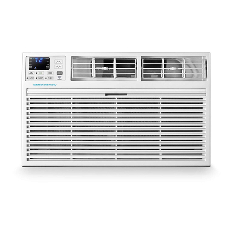
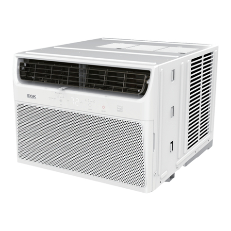
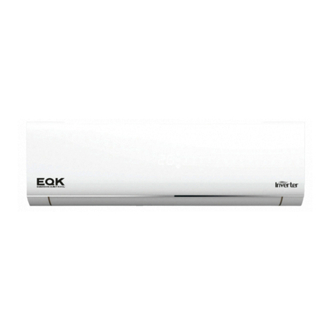
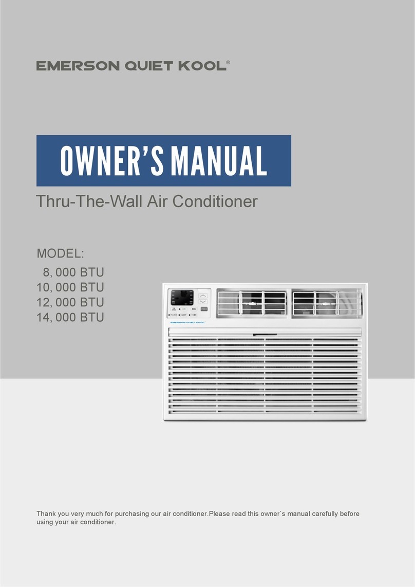
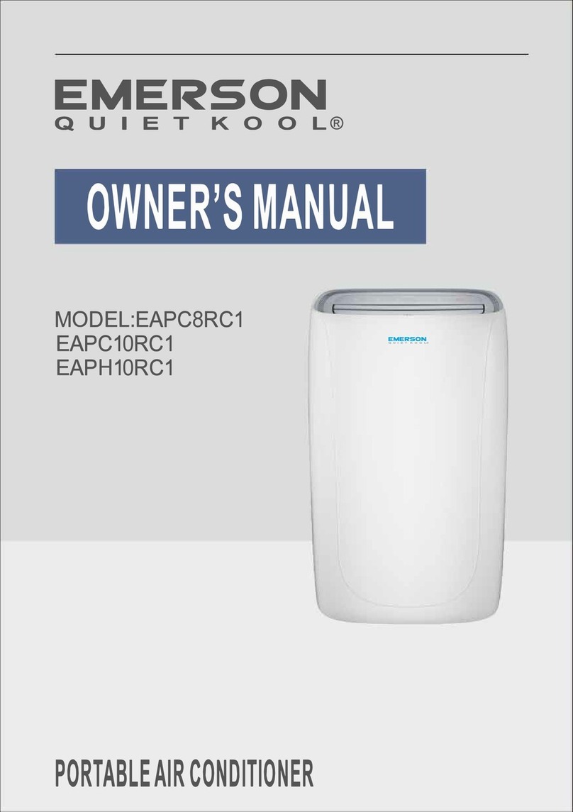
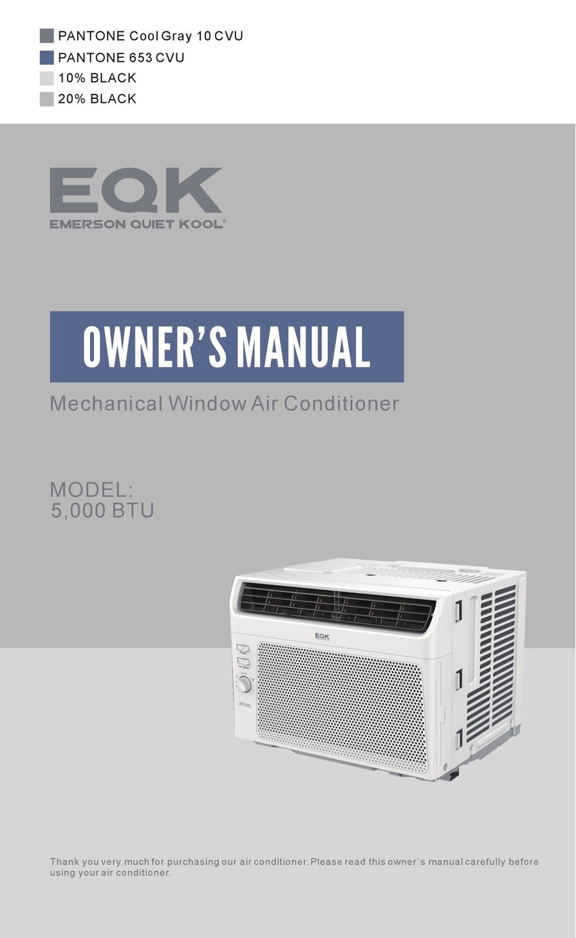
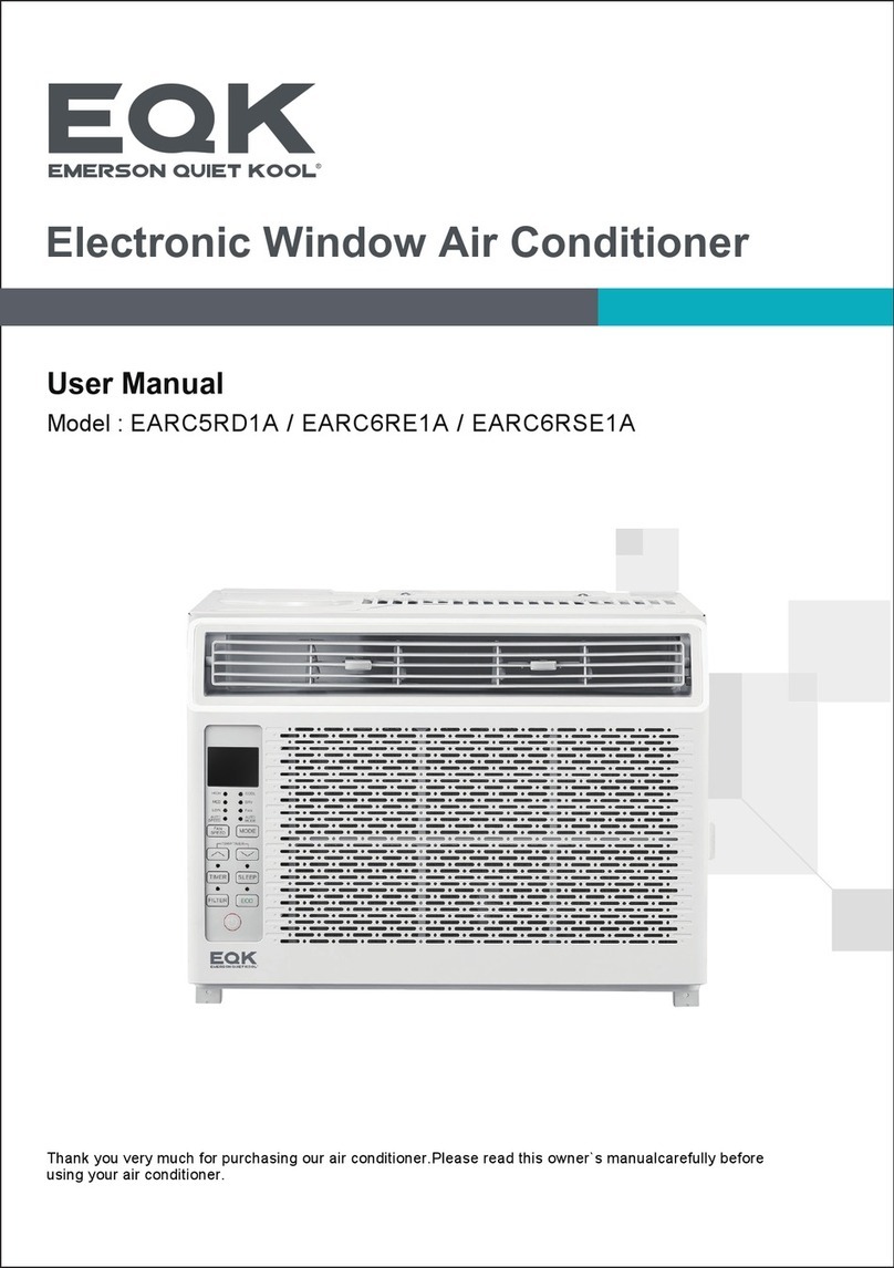
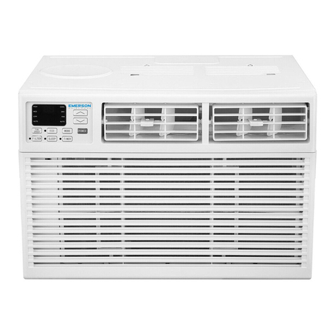
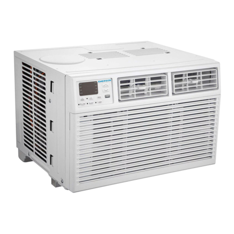
Emerson Quiet Kool 21 SEER Series User manual

意大利文
INSTALLATION

Safety Precautions 4
Safety Instructions 1
Preset 3
Safeguarding the Environment 3
Site Instructions
Suggested Tools
7
6
Power and Wiring 10
Installation Diagram 5
Outdoor Unit Installation 8
Installation Instructions 5
Contents
3
Preparation before Use
Remote controller operating instructions.See"remote controller
instructions".
For outdoor unit only, please refer to the indoor unit’s USE AND
INSTALLTION INSTRUCTIONS for the indoor unit.
Vacuum Testing and Charging 12

1
Safety Instructions
1. To guarantee the unit work normally, please read the manual carefully before
installation, and try to install strictly according to this manual.
2. Do not let air enter the refrigeration system or discharge refrigerant when moving the
air conditioner.
6. After installing, the consumer must operate the air conditioner correctly
according to this manual,keep a suitable storage for maintenance and moving of
the air conditioner in the future.
5. There must be an air-break switch.
4. Check the connecting cables and pipes carefully, make sure they are correct and firm
before connecting the power of the air conditioner.
T 3.15A or T 5A 250V
T 20A 250V
3. Properly ground the air conditioner into the earth.
9. Warning: Risk of electric shock can cause injury or death: Disconnect all remote
electric power supplies before servicing .
8. A residual current device(RCD)with the rating of above 10mA shall be
incorporated in the fixed wiring according to the national rule.
10. The best length of the connecting pipe between the indoor unit and outdoor
unit is less than 7.5 meters(24.6ft). It will affect the efficiency of the air conditioner
if the distance longer than that length.
12. This appliance can be used by children aged from 8 years and above and
persons with reduced physical, sensory or mental capabilities or lack of
experience and knowledge if they have been given supervision or instruction
concerning use of the appliance in a safe way and understand the hazards I
nvolved. Children shall not play with the appliance. Cleaning and user
maintenance shall not be made by children without supervision.
13. The batteries in remote controller must be recycled or disposed of properly.
Disposal of Scrap Batteries --- Please discard the batteries as sorted municipal
waste at the accessible collection point.
11. This appliance is not intended for use by persons (including children) with
reduced physical, sensory or mental capabilities, or lack of experience and
knowledge, unless they have been given supervision or instruction concerning
use of the appliance by a person responsible for their safety.Children should be
supervised to ensure that they do not play with the appliance.
Model
9K-12K(208/230V)
Fuse of Indoor unit
18K(208/230V)
24K-36K(208/230V)
Fuse of outdoor unit
T 3.15A or T 5A 250V
7. The Fuse of the unit:
T 3.15A or T 5A 250V
12K(115V) T 25A 250V
T 3.15A or T 5A 250V
9K(115V) T 25A 250V
T 15A 250V
T 30A 250V

2
Safety Instructions
15. If the supply cord is damaged, it must be replaced by the manufacturer, its
service agent or similarly qualified persons in order to avoid a hazard.
14. If the appliance is fixed wiring, the appliance must be fitted with means for
disconnection from the supply mains having a contact separation in all poles
that provide full disconnection under overvoltage category III conditions, and
these means must be incorporated in the fixed wiring in accordance with the
wiring rules.
18. The appliance shall not be installed in the laundry.
16. The appliance shall be installed in accordance with local electrical safety
regulations and National Electrical Codes(NEC).
17. The air conditioner must be installed by professional or qualified persons.
20. Regarding to maintenance, please refer to section “Care and Maintenance”.
19. Regarding to installation, please refer to section “Installation instructions”.

3
Preparation before Use
The air conditioner has an Auto-Restart function.
Each time after the remote control is replaced with new batteries or is energized, auto presetting
heat pump.If the air conditioner you purchased is a Cooling Only one, heat pump remote controller can also be
used.
remote control
Remote Control Presetting
Before using the air conditioner, be sure to check and preset the following.
Auto Restart Presetting
Hold down any button on remote control to activate the back light. It automatically shuts off 10 seconds
later.
Note: Back-light is an optional function.
Back-light Function (optional)of Remote Control
This appliance is made of recyclable or re-usable material. Scrapping must be carried out in
compliance with local waste disposal regulations. Before scrapping it, make sure to cut off the
mains cord so that the appliance cannot be re-used.
For more detailed information on handling and recycling this product, contact your local authorities
who deal with the separate collection of rubbish or the shop where you bought the appliance.
SCRAPPING OF APPLIANCE
This marking indicates that this product should not be disposed
with other household wastes throughout the North America. To
prevent possible harm to the environment or human health from
uncontrolled waste disposal, recycle it responsibly to promote
the sustainable reuse of material resources. To return your
used device, please use the return and collection systems or
contact the retailer where the product was purchased.
They can take this product for environmental safe recycling.
Note
Preset
Safeguarding the environment
When charging refrigerant into the system, make sure to charge in liquid state, if
the refrigerant of the appliance is R410A.Otherwise, chemical composition of
refrigerant (R410A) inside the system may change and thus affect performance
of the air conditioner.
According to the character of
pressure of the tube is very high, so be sure to be careful when you install and
repair the appliance.
refrigerant (R410A,the value of GWP is 2088), the
If the supply cord is damaged, it must be replaced by the manufacturer, its
service agent or similarly qualified persons in order to avoid a hazard.
The air conditioner must be installed by trained, qualified installers
and service mechanics.
The temperature of refrigerant circuit will be high, please keep the
interconnection cable away from the copper tube.

Safety Precautions
Symbols in this Use and Care Manual are interpreted as shown below.
Be sure not to do.
Pay attention to such a situation.
Grounding is essential.
Warning: Incorrect handling could
cause a serious hazard, such as death,
serious injury, etc.
4
Do not use the power supply circuit
breaker or pull off the plug to turn it off
during operation. This may cause a fire
due to spark, etc.
Keep the power supply circuit breaker
or plug from dirt. Connect the power
supply cord to it firmly and correctly,
lest an electric shock or a fire break out
due to insufficient contact.
Use correct power supply in
accordance with the rating plate
requirement. Otherwise, serious
faults or hazard may occur or a
fire maybe break out.
Do not knit, pull or press the power supply
cord, lest the power supply cord be broken.
An electric shock or fire is probably caused
by a broken power supply cord.
Never insert a stick or similar obstacle
to the unit. Since the fan rotates at high
speed, this may cause an injury.
Do not repair the appliance by yourself.
If this is done incorrectly, it may cause an
electric shock, etc.
Turn off the appliance by remote control
firstly before cutting off power supply if
malfunction occurs.
It is harmful to your health if the cool air
reaches you for a long time. It is advisable
to let the air flow be deflected to all the room.
Prevent the air flow from reaching the gas
burners and stove.
Do not touch the operation buttons
when your hands are wet.
Do not put any objects on the outdoor
unit.
It is the user's responsibility to make the
appliance be grounded according to
local codes or ordinances by a licenced
technician.
OFF OFF
ON
ON
ON/OF F
MODE FAN
SWING SLEEP SUPER
SMART IF EEL DIMMER
TIMER O N TIME R OFF CLOCK
ON
OFF
ON
OFF

5
Installation Instructions
Installation diagram
Air intake distance from
the wall should be
over 250mm/10in
Air intake distance from the wall
over 250mm/10in
air outlet distance from the wall
should be over 500mm/20in
should be over 250mm/10in
Above figure is only a simple presentation of the unit, it may not match the external appearance of the unit you purchased.
Installation must be performed in accordance with the national wiring standards by authorized personnel only.
outdoor unit
Distance from the obstacle
should be over 500m/20in

6
Installation Instructions
Suggested Tools
In order to install your air-conditioner more conveniently and safely, you might use
those special tools listed below.
Standard Wrench
Screw Driver
Hex Keys or Allen Wrenches
Adjustable/Crescent Wrench
Torque wrench
Drill & Drill Bits
Manifold and Gauges
Vacuum Pump
Clamp on Amp Meter
Level
Work Gloves
Safety Glasses
Pipe Cutter
Refrigerant Scale
R410A Flaring Tool
Micron Gauge
Hole Saw

7
Installation Instructions
Site Instructions
Site for Installing Outdoor Unit
Where it is convenient to install and well ventilated.
Avoid installing it where flammable gas could leak.
Keep the required distance apart from the wall.
Keep the outdoor unit away from greasy dirt, vulcanization gas exit.
Avoid installing it by the roadside where there is a risk of muddy
water.
A fixed base where it is not subject to increased operation noise.
Where there is not any blockage of the air outlet.
Avoid installing under direct sunlight, in an aisle or sideway,
or near heat sources and ventilation fans. Keep away from
flammable materials, thick oil fog, and wet or uneven places.
If the height or pipe length is out of the scope of the table, please consult the merchant.
Model
9K-18K 20
Required amount of
additional refrigerant (g/m)
24K
30K-36K
30
40
In case the pipe length is more than 7.5m(24.6ft), the refrigerant should be charged additionally, according
to below table.
Outdoor unit
Indoor unit
Pipe length is
20 meters(65.4ft) Max.
be less than 5m (16.4ft)
Height should
Outdoor unit is higher than indoor unit
Installation of indoor unit refers to the indoor unit installation manual.

8
Installation Instructions
The condensate drains from the outdoor unit when the unit operates in heating mode. In
order not to disturb your neighbor and protect the environment, install a drain port and
a drain hose to direct the condensate water. Just install the drain port and rubber washer
to the chassis of the outdoor unit, then connect a drain hose to the port as the right figure
demonstrates.
Outdoor Unit Installation
Drain hose
(prepared by user)
Washer
Drain port
Rubber pad (optional)
Place under the leg pedestal
2. Install Ground Pad or Wall Hangers
1. Install Condensate Drain for Outdoor Unit
1.Determine proper location for outdoor unit.
2.Follow all instructions provided by manufacturer for installing wall hangers
rubber pad.
3.Verify the wall hangers or rubber pad can safely support the weight of the
outdoor unit.
4.Verify the wall hangers or rubber pad is level and meets all outdoor
dimensional clearance.
5.Fix with bolts and nuts tightly on a flat and strong floor.
If installed on the wall or roof, make sure to fix the supporter well to prevent it
from shaking due to serious vibration or strong wind.

Pipe diameter
/inch(mm)
Nut Size
/inch(mm)
Tightening Torque
ft-lbs N-m
1/4(6.35) 1/4(17) 11 to 15 15 to 20
3/8(9.5) 3/8(22) 22 to 26 30 to 35
1/2(12.7) 1/2(25) 37 to 41 50 to 55
5/8(15.9)
3/4(19)
5/8(29)
3/4(32)
44 to 48
52 to 55
60 to 65
70 to 75
9
Installation Instructions
3. Piping Connections to Outdoor Unit
Service
Valve Cover
Apply a small amount of refrigerant oil to the flare connection
on the refrigerant pipe.
Properly align piping and tighten flare nut using a standard
wrench and a torque wrench as shown in the indoor piping section.
Carefully tighten flare nuts to correct torque level referring to the
following Torque Table:
Carefully bend and adjust length of refrigerant pipes to meet
outdoor unit service valves connection with proper tools to
avoid kinks.
Remove service valve cover( if provided) to access the service
valves and refrigerant ports.
Torque Table
Note: Over tightening may damage flare connections and cause leaks.
WARNING
Florida wind load requirements state that outdoor unit must be anchored to
concrete pad using four 3/8-in diameter power wedge bolt plus(or equivalent)
with 1-in diameter fender washers. Anchor bolts must be embedded into
3000 PSI minimum concrete at a distance of 4 1/2- in from any concrete edge.
The concrete thickness must exceed 1.5 times the anchor depth.

10
Connecting of the Cable
Outdoor Unit
1) Remove the from the unit by loosening cable cross board
the screw. Connect the wires to the terminals on the
control board individually as follows.
2) Secure the power cord onto the control
board with cable clamp.
3) Reinstall the to the original position cable cross board
with the screw.
4) Use a recognized circuit breaker between the power
source and the unit. A disconnecting
disconnect all supply lines must be fitted.
device to adequately
Outdoor unit
Installation Instructions
Caution:
1. Never fail to have an individual power circuit specifically for the air conditioner. As for the method of
wiring, refer to the circuit diagram posted on the inside of the access door .
2. Comfirm that the cable thickness is as specified in the power source specification.
3. Check the wires and make sure that they are all tightly fastened after cable connection.
4. Be sure to install an earth leakage circuit breaker in wet or moist areas.
The figures in this manual are based on the external
view of a standard model. Consequently, the shape
may differ from that of the air conditioner you have
selected.
Cable Specifications
Attention:
The plug must be accessible even after the installation of the appliance in case there is a need to
disconnect it. If not possible, connect appliance to a double-pole switching device with contact
separation of at least 3 mm placed in an accessible position even after installation.
Wire Hole
Cable Cross Board
Power and Wiring
capacity(Btuh) Power cord Power connecting cord
Type Normal cross-
sectional areas Type Normal cross-
sectional areas
9K-12K(208/230V) SJ TW 3X16 AWG SJ TW 4X18 AWG
18K(208/230V) SJ TW 3X14 AWG SJ TW 4X18 AWG
24K-36K(208/230V) SJ TW 3X12 AWG SJ TW 4X18 AWG
9K,12K(115V) SJ TW 3X14 AWG SJ TW 4X18 AWG

11
Installation Instructions
Make sure that the color of the wires in the outdoor unit and terminal No. are the same as those
of the indoor unit.
Wiring diagram
The diagram is reference only, and the actual terminal shall prevail.
Warning: Before obtaining access to terminals, all supply circuits must
be disconnected.
Terminal
Indoor unit
Terminal
Outdoor unit
Power connecting cord
Green
White
Red
Black
1(N)
2(L)
3(SI)
Green
White
Red
Black
1(N)
2(L)
3(SI)
Power supply
L1
L2
GN
WHT
BLK
(1) 208/230V
(2) 115V
Terminal
Indoor unit
Terminal
Outdoor unit
Power connecting cord
Green
White
Red
Black
1(N)
2(L)
3(SI)
Green
White
Red
Black
1(N)
2(L)
3(SI)
Power supply
N
L
GN
WHT
BLK

The air which contains moisture remaining in the refrigeration cycle may cause a malfunction on the
compressor. After connecting the indoor and outdoor units, release air and moisture from the refrigerant
cycle using a vacuum pump, as shown below.
Installation Instructions
Vacuum Testing and Charging
Note: To protect the environment, be sure not to discharge the refrigerant to the air directly.
See next page for air purging steps.
Refrigerant flow direction 2-way valve
(6) Open 1/4 turn
valve cap
(1) Turn
(8) Tighten
(2) Turn
3-way valve
(8) Tighten
(1) Turn
(7) Turn to fully open the
valve
(7) Turn to fully open the valve
(8) Tighten
3-way valve diagram
connect to indoor unit
open position
spindle
service port cap
Service
port
Connect to outdoor unit
Valve core
needle
indoor unit
Valve cap
(1) Unscrew and remove caps from 2 and 3-way valves.
(4) Start vacuum pump for 10-15 minutes until reaching a vacuum of 10 mm Hg absolutes.
(6) Open 2-way valve ,1/4 turn, then close it after 10 seconds. Check tightness of all joints using liquid
soap or an electronic leak detector.
(7) Turn 2 and 3-way valves stem to fully open the valves. Disconnect the flexible vacuum pump hose.
(8) Replace and tighten all valve caps.
(5) With vacuum pump still running close the low pressure knob on vacuum pump manifold. Then stop
the vacuum pump.
(2) Unscrew and remove cap from service valve.
(3) Connect vacuum pump flexible hose to the service valve.
How to Vacuum Air Tubes:
12
Vacuum pump

1、第一个红框处, 改为REMOTE
2、第二个红框处,改为21 SEER
3、第三个红框处,内容去掉,换成带EQK LOGO的遥控器图片,具体位置见下面第二个图,左右居中位置,原有的那部分文字和图片删除;
4、封底,加上售后电话,具体见下面第三个图,文字内容如下:
REMOTE
1、第一个红框处,使用说明书不需要改,安装说明书改为INSTALLATION, 字体长的话,蓝色条框拉长点。
2、第二个红框处,改为21 SEER
3、第三个红框处,BUT改为BTU, 36000BTU去掉;
4、第四个红框处,用客户下单的TR面板内机图, 带LOGO
5、封底,加上售后电话,同刚才发的邮件一样,同遥控器说明书上面内容。
INSTALLATION


T 25A 250V


3
Preparación antes del uso
Nota
Other manuals for 21 SEER Series
1
Table of contents
Other Emerson Quiet Kool Air Conditioner manuals

Emerson Quiet Kool
Emerson Quiet Kool 15,000 BTU User manual

Emerson Quiet Kool
Emerson Quiet Kool E TC08RE1T Series User manual

Emerson Quiet Kool
Emerson Quiet Kool EARC5MD1H User manual

Emerson Quiet Kool
Emerson Quiet Kool EATC14RSD2T User manual

Emerson Quiet Kool
Emerson Quiet Kool EAPC8RC1 User manual

Emerson Quiet Kool
Emerson Quiet Kool EARC5RD1A User manual

Emerson Quiet Kool
Emerson Quiet Kool 19 SEER Series User manual

Emerson Quiet Kool
Emerson Quiet Kool EARC6RE1 User manual

Emerson Quiet Kool
Emerson Quiet Kool EBTC08RE1T User manual

Emerson Quiet Kool
Emerson Quiet Kool EARC8RE1A User manual