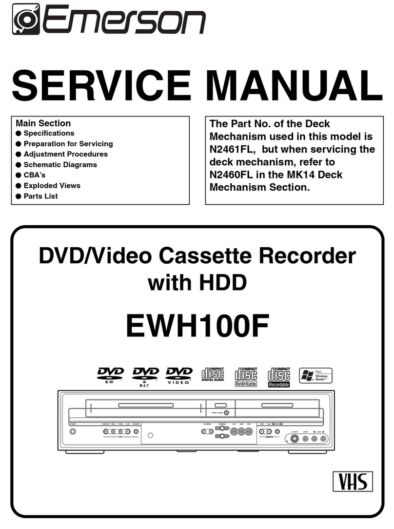
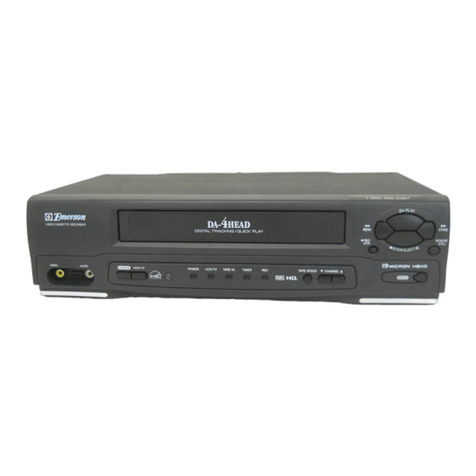
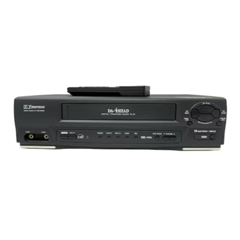
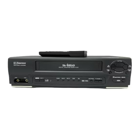
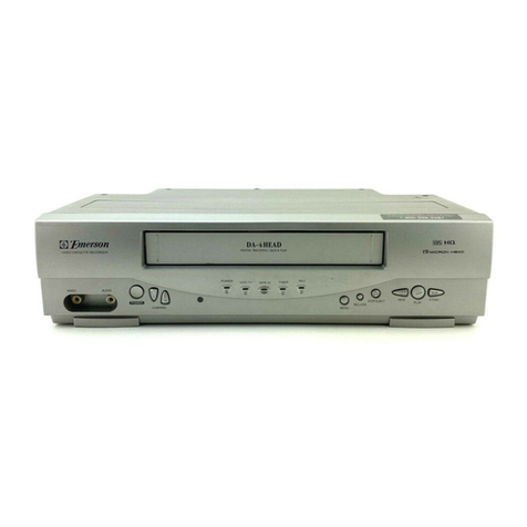
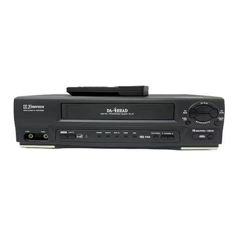
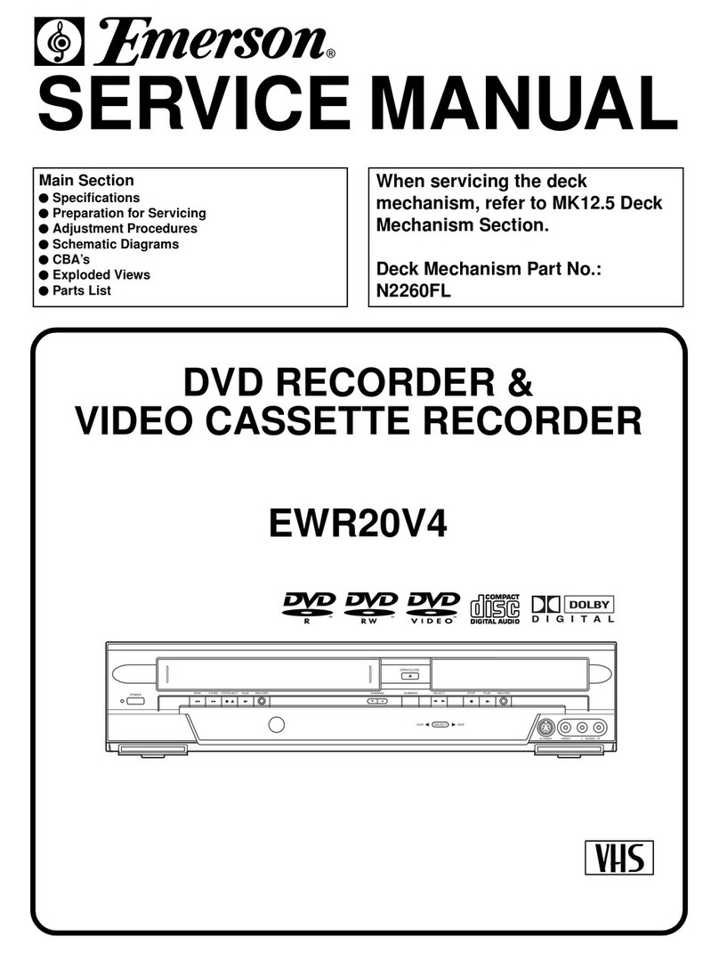
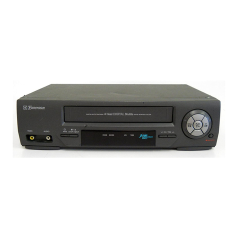
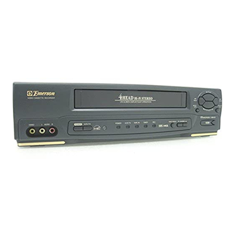
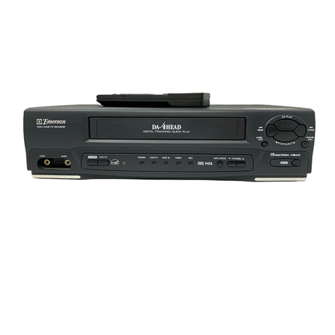
Emerson EWR20V5 User manual

SERVICE MANUAL
DVD RECORDER &
VIDEO CASSETTE RECORDER
SUPPLEMENT
This service manual shows only the differences between the
model EWR20V5 and the original model DVR90VF.
All other information is described in the service manual of the
model DVR90VF.
VIDEOS
-
VIDEO L
-
AUDI O
-
R
POWER REW F.FWD PLAY RECORD
STOP/EJECT
DUBBING
OPEN/CLOSE
VCR
SELECT
SELECT
DVD
STOP PLAYCHANNEL RECORD
EWR20V5

IMPORTANT SAFETY NOTICE
Proper service and repair is important to the safe, reliable operation of all
Funai Equipment. The service procedures recommended by Funai and de-
scribed in this service manual are effective methods of performing service
operations. Some of these service special tools should be used when and
as recommended.
It is important to note that this service manual contains various CAUTIONS
and NOTICES which should be carefully read in order to minimize the risk of
personal injury to service personnel. The possibility exists that improper
service methods may damage the equipment. It also is important to under-
stand that these CAUTIONS and NOTICES ARE NOT EXHAUSTIVE. Funai
could not possibly know, evaluate and advice the service trade of all con-
ceivable ways in which service might be done or of the possible hazardous
consequences of each way. Consequently, Funai has not undertaken any
such broad evaluation. Accordingly, a servicer who uses a service proce-
dure or tool which is not recommended by Funai must first use all precau-
tions thoroughly so that neither his safety nor the safe operation of the
equipment will be jeopardized by the service method selected.
TABLE OF CONTENTS
Block Diagrams . . . . . . . . . . . . . . . . . . . . . . . . . . . . . . . . . . . . . . . . . . . . . . . . . . . . . . . . . . . . . . . . . . . . . . . . . . 1-1
Schematic Diagrams / CBA's and Test Points. . . . . . . . . . . . . . . . . . . . . . . . . . . . . . . . . . . . . . . . . . . . . . . . . . . 2-1
Wiring Diagram < VCR Section > . . . . . . . . . . . . . . . . . . . . . . . . . . . . . . . . . . . . . . . . . . . . . . . . . . . . . . . . . . . . 3-1
Wiring Diagram < DVD Section > . . . . . . . . . . . . . . . . . . . . . . . . . . . . . . . . . . . . . . . . . . . . . . . . . . . . . . . . . . . . 3-2
Different parts from the original model (DVR90VF) . . . . . . . . . . . . . . . . . . . . . . . . . . . . . . . . . . . . . . . . . . . . . . 4-1

1-1
Video Output Select Block Diagram
E9600BLVOS
DVD MAIN CBA UNIT MAIN CBA
CN601
77
VIDEO-Y(I/P)
99VIDEO-C
55
VIDEO-Cb/Pb
33
VIDEO-Cr/Pr
VIDEO-Y(I/P)
VIDEO-C
VIDEO-Cb/Pb
VIDEO-Cr/Pr
JK1401
S-VIDEO
OUT
CN201
3 4
2
1
IC1405 (VIDEO DRIVER)
4dB
AMP
2dB
AMP
LPF DRIVER
YC
IC1406
(OUTPUT SELECT)
11
4dB
AMP
2dB
AMP
LPF DRIVER
6
10
4dB
AMP
2dB
AMP
LPF DRIVER
8
VIDEO-Cb/Pb
OUT
VIDEO-Y
OUT
VIDEO-Cr/Pr
OUT
JK1403
VIDEO OUT
(COMPOSITE)
JK751
TP751
V-OUT
3
TO DIGITAL SIGNAL
PROCESS BLOCK
DIAGRAM
DVD-VIDEO(DUB)
SW CTL
PB/EE-VIDEO
TO SYSTEM CONTROL
BLOCK DIAGRAM
TO VIDEO
BLOCK DIAGRAM
REC VIDEO SIGNAL PB VIDEO SIGNAL
WF4
WF5
WF6
WF1
WF7
WF8
2
15
1
109 11
OUTPUT-SELECT
Q391
BUFFER
TU900 (TUNER UNIT)
6VIDEO-IN
(DVD VCR DUBBING)
1
13
14
15
4dB
AMP
2dB
AMP
LPF DRIVER
8dB
AMP
-6dB DRIVER
WF12
BLOCK DIAGRAMS < VCR SECTION >

2-1 E9600_SC
SCHEMATIC DIAGRAMS / CBA’S AND TEST POINTS
Standard Notes
WARNING
Many electrical and mechanical parts in this chassis
have special characteristics. These characteristics
often pass unnoticed and the protection afforded by
them cannot necessarily be obtained by using
replacement components rated for higher voltage,
wattage, etc. Replacement parts that have these
special safety characteristics are identified in this
manual and its supplements; electrical components
having such features are identified by the mark “#” in
the schematic diagram and the parts list. Before
replacing any of these components, read the parts list
in this manual carefully. The use of substitute
replacement parts that do not have the same safety
characteristics as specified in the parts list may create
shock, fire, or other hazards.
Notes:
1. Do not use the part number shown on these
drawings for ordering. The correct part number is
shown in the parts list, and may be slightly
different or amended since these drawings were
prepared.
2. All resistance values are indicated in ohms
(K = 103, M = 106).
3. Resistor wattages are 1/4W or 1/6W unless
otherwise specified.
4. All capacitance values are indicated in µF
(P = 10-6 µF).
5. All voltages are DC voltages unless otherwise
specified.

2-2 E9600_SC
LIST OF CAUTION, NOTES, AND SYMBOLS USED IN THE SCHEMATIC DIAGRAMS ON
THE FOLLOWING PAGES:
1. CAUTION:
FOR CONTINUED PROTECTION AGAINST FIRE HAZARD, REPLACE ONLY WITH THE
SAME TYPE FUSE.
ATTENTION: POUR UNE PROTECTION CONTINUE LES RISQES D'INCELE N'UTILISER
QUE DES FUSIBLE DE MÊME TYPE.
RISK OF FIRE-REPLACE FUSE AS MARKED.
2. CAUTION:
Fixed Voltage (or Auto voltage selectable) power supply circuit is used in this unit.
If Main Fuse (F1001) is blown, first check to see that all components in the power supply circuit are not
defective before you connect the AC plug to the AC power supply. Otherwise it may cause some components
in the power supply circuit to fail.
3. Note:
1. Do not use the part number shown on the drawings for ordering. The correct part number is shown in the
parts list, and may be slightly different or amended since the drawings were prepared.
2. To maintain original function and reliability of repaired units, use only original replacement parts which are
listed with their part numbers in the parts list section of the service manual.
4. Mode: SP/REC
5. Voltage indications for PLAY and REC modes on the schematics are as shown below:
6. How to read converged lines
7. Test Point Information
A V
F
This symbol means fast operating fuse.
Ce symbole represente un fusible a fusion rapide.
2315.0
(2.5)
PLAY mode
STOP mode
5.0
The same voltage for
both PLAY & STOP modes Indicates that the voltage
is not consistent here.
< DVD Section >
2315.0
(2.5)
< >
PLAY mode
REC mode
DVD mode
5.0
The same voltage for
both PLAY, REC & DVD
modes Indicates that the voltage
is not consistent here.
< VCR Section >
Unit: Volts
3
2
1
ABCD
1-B1
1-D3
AREA D3
AREA B1
1-D3
Distinction Area
Line Number
(1 to 3 digits)
Examples:
1. "1-D3" means that line number "1" goes to the line number
"1" of the area "D3".
2. "1-B1" means that line number "1" goes to the line number
"1" of the area "B1".
: Indicates a test point with a jumper wire across a hole in the PCB.
: Used to indicate a test point with a component lead on foil side.
: Used to indicate a test point with no test pin.
: Used to indicate a test point with a test pin.
2-3
Main 2/7, Power SW, Function & Sensor Schematic Diagram < VCR Section >
E9600SCM2
5G 4G 3G 2G 1G
7G 6G
a
d
g
h
h
gcb
ef
REPEAT
PM
REC
VCD VCR DVD
R
XP SP
LP EP
SLP
P.SCAN
SEP
W
CD
T C
7G 6G 5G 4G 3G 2G 1G
a
b
c
d
e
f
g
c
d
e
f
gg
c
d
e
f
g
c
d
e
f
g
c
d
e
f
g
c
d
e
f
g
hh
i
a
b
a
b
a
b
a
b
a
b
FIP501 MATRIX CHART
REPEAT
PM
REC
VCD VCR DVD
R
XP
SP
LP
EP
SLP
P.SCAN
SEP
W
CD
TC
MAIN 2/7
Ref No. Position
IC571 K-2
Q561 I-2
Q562 I-2
Q563 H-2
CN2209 H-4
CN2211 H-4
TP502 I-3
TP506 K-1
TP507 K-1
IC
TRANSISTORS
TEST POINTS
CONNECTORS

2-4
Main 5/7 Schematic Diagram < VCR Section >
E9600SCM5
MAIN 5/7
Ref No. Position
IC800 AA-2
IC803 BB-1
IC805 Y-2
IC900 Z-3
Q1303 AA-1
Q1304 AA-1
Q1305 AA-1
CN201 CC-3
CN1609 X-1
ICS
CONNECTORS
TRANSISTORS

2-5
Main 6/7 Schematic Diagram < VCR Section >
E9600SCM6
MAIN 6/7
Ref No. Position
IC804 EE-1
IC1405 FF-4
IC1406 FF-2
Q391 GG-2
Q804 FF-1
Q805 FF-1
Q806 FF-1
Q1351 GG-1
TP751 HH-4
TP753 HH-4
TP754 HH-4
TEST POINTS
ICS
TRANSISTORS

2-6 E9600SCD4
DVD Main 4/6 Schematic Diagram < DVD Section >
NOTE:
1. The order of pins shown in this diagram is different from that of actual IC601.
2. IC601 is divided into six and shown as IC601 (1/6) ~ IC601 (6/6) in this DVD Main Schematic Diagram Section.
DVD MAIN 4/6
Ref No. Position
IC601(1/6) T-4
IC601(2/6) S-2
IC901 V-2
IC902 V-3
Q801 S-3
Q802 S-3
CN501 X-4
CN601 X-2
CONNECTORS
TRANSISTORS
ICS

2-7
TO SENSOR CBA
(START-SENSOR)
SW-P
VR501
CTL
TP513
RF-SW
TP302
WF2
C-PB
TP301
WF3
V-OUT
TP751
WF1
TO SENSOR CBA
(END-SENSOR)
S-INH
TP502
BE9610F01013A
Main CBA Top View
Sensor CBA Top View
BHB300F01014A
BHB300F01014B

2-8
PIN 11 OF
TU900
PIN 12 OF
TU900
WF11
WF12
PIN 11 OF
TU900
WF13
PIN 12 OF
TU900
WF14
PIN 18 OF
TU900
WF15
PIN 2 OF
IC1406
WF6
PIN 17 OF
CN201
PIN 3 OF
CN201
WF8
PIN 5 OF
CN201
WF7
WF9
PIN 9 OF
CN201
WF5
PIN 7 OF
CN201
WF4
PIN 1 OF
CN2204
WF10
Main CBA Bottom View
BE9610F01013A

2-9
Jack CBA Top View Jack CBA Bottom View
Function CBA Top View Function CBA Bottom View
Power SW CBA Top View Power SW CBA Bottom View
BE9610F01013D
BE9610F01013CBE9610F01013B
Junction CBA Top View Junction CBA Bottom View
BE9600F01021B

WIRING DIAGRAM < VCR SECTION >
E9600WI3-1
AC HEAD
ASSEMBLY
AUDIO
ERASE
HEAD
CONTROL
HEAD
AUDIO
HEAD
CYLINDER
ASSEMBLY
CN501
CN502
CN504
CN253
CN2209
CN2211
W002 CN2210
FULL
ERASE
HEAD
FE HEAD
VIDEO
(R)1
HEAD
VIDEO
(L)1
HEAD
VIDEO
-IN2
S-VIDEO
IN
AUDIO(R)
-IN2
AUDIO(L)
-IN2
FRONT
VIDEO
(L)2
HEAD
VIDEO
(R)2
HEAD
Hi-Fi
AUDIO
(R) HEAD
Hi-Fi
AUDIO
(L) HEAD
MAIN CBA
(DECK ASSEMBLY)
SENSOR CBA
FUNCTION CBA
CN2212
POWER SW CBA
SENSOR CBA
TO WIRING
DIAGRAM
<DVD SECTION>
TO
DVD MAIN
CBA UNIT
CN501
(W01)
TO
DVD MAIN
CBA UNIT
CN601
(W02)
ANT-IN ANT-OUT
AUDIO(L)
-IN1
AUDIO(R)
-OUT2
VIDEO
-IN1
AUDIO(L)
-OUT2
AUDIO(R)
-IN1
VIDEO-Y
OUT
VIDEO-
Cr/Pr
OUT
VIDEO-
Cb/Pb
OUT
AUDIO(L)
-OUT1
AUDIO(R)
-OUT1
S-VIDEO
IN
S-VIDEO
OUT
VIDEO
OUT
REAR
DIGITAL
AUDIO
OUT
OPEN/CLOSE-SW
11
DUBBING-SW
22
1
CN1609 W03 CN1605
JACK CBA
C-IN2
11
Y-IN2
22
GND
33
VIDEO-IN2
44
GND
55
AUDIO(L)-IN2
66
GND
77
AUDIO(R)-IN2
88
W001
AL+5V
11
GND
33
GND
33
POWER-SW
44
POWER-LED
2 2
CN102
2FAN-LOCK
FAN
CN1612
CN1607 CN101
CN1610
CN1608
CN1611
JUNCTION CBA
6
2
3
4
5
7
8
9
1
6
2
3
4
5
7
8
9
GND
AL+44V
AL+12V(1)
AL+12V(2)
DVD+5V
AL+5V
GND
GND
GND
AL-30V
NU
AL+1.5V
GND
GND
AL+4V
F1
F2
POW-P
1
2
3
4
5
6
7
8
9
1
1
2
2
3
4
5
6
1
2
3
4
5
6
7
8
9
10
11
12
1
2
3
4
5
6
7
1
2
3
4
5
6
7
8
9
8
9
33
5
9
12
15
1
2
4
6
7
8
10
11
13
14
16
17
18
POWER SUPPLY
CBA
AC CORD
Hi-Fi-AUDIO(R)
Hi-Fi-COM
Hi-Fi-AUDIO(L)
VIDEO-COM
VIDEO(R)-2
VIDEO-COM
VIDEO(L)-2
VIDEO(L)-1
VIDEO(R)-1
AL+12V(1)
P-ON+5V(1)
C-F/R
C-FG
C-CONT
GND
LM-FWD/REV
D-CONT
D-PFG
GND
AL+12V
AL+18V
FE-H
FE-H GND
AE-H
AE-H/FE-H
A-COM
AUDIO-PB/REC
CTL(+)
CTL(-)
1
POW-P
F2
2
AL+4V4
GND5
GND6
AL+1.5V7
NU
8
AL-30V9
GND10
GND11
GND12
GND13
AL+5V14
DVD+5V15
AL+12V(2)16
AL+12V(1)17
AL+44V18
F13
FAN
1
W003
W004
LOADING
MOTOR
CAPSTAN
MOTOR
M
DRUM
MOTOR
PG
SENSOR
M
CAPSTAN
MOTOR
MOTOR
DRIVE
CIRCUIT
M
CN201
VIDEO-Y(I) (NU)
1
GND 2
VIDEO-Cr/Pr 3
GND 10
VIDEO-C 9
GND 4
VIDEO-Cb/Pb 5
GND 6
VIDEO-Y(I/P) 7
GND 8
CN2204
GND 16
AUDIO(R)-IN 11
GND 12
AUDIO(L)-IN 13
GND 14
AUDIO(R)-OUT
15
AUDIO(L)-OUT
17
GND 18
DVD-AUDIO-MUTE
19
AUDIO+5V 20
VIDEO-Y/CVBS
21
GND 22
VIDEO-C 23
GND 24
SUB-SCLK 25
REG-CONT2 26
SUB-TXD
27
RDY 28
SUB-RXD
29
SYS-RESET 30
SPDIF 1
GND 2
EV+10.5V 4
EV+10.5V 5
EV+10.5V 6
GND 7
GND 8
GND 9
GND 10
P-ON+5V 11
P-ON+5V 12
P-ON+5V 13
EV+2.4V 14
EV+2.4V 15
EV+2.4V 16
EV+2.4V 17
GND 18
GND 3
GND 19
P-ON+2.5V 20
P-ON+2.5V 21
P-ON+2.5V 22
GND 23
GND 24
P-ON+3.3V 25
P-ON+3.3V 26
P-ON+3.3V 27
GND 28
GND 29
GND 30

WIRING DIAGRAM < DVD SECTION >
E9600WID3-2
TO MAIN
CBA CN2204
(W01)
TO WIRING
DIAGRAM
<VCR SECTION>
TO MAIN
CBA CN201
(W02)
DVD MECHANISM
PICKUP
RELAY
CBA
ENCODER CBA
LOADER CBA
CN101
CN1001
CN1003
910 U
109 V
CN601
VIDEO-Y(I)
(NU)
1
GND 2
VIDEO-Cr/Pr 3
GND 10
VIDEO-C 9
GND 4
VIDEO-Cb/Pb 5
GND 6
VIDEO-Y(I/P) 7
GND 8
CN501
GND 16
AUDIO(R)-IN 11
GND 12
AUDIO(L)-IN 13
GND 14
AUDIO(R)-OUT
15
1FCS(+)
4TRK(-)
3TRK(+)
2 FCS(-)
6 TILT(-)
5 TILT(+)
7GND
9GND
11 FPD-SW
8THERMO
12
VC-FPD
14 VC-PD
15 H
16 D
17 C
18 F
19 NU
20 NU
21 SW
22 RF(+)
23 RF(-)
24 E
25 B
26 A
27 G
28 GND
29 VCC2
30 IIN3
31 IIN2
32 IIN1
33 GND
34 XOUTEN3
35 GND
36 XOUTEN2
37 GND
38 OSCEN
39 LDEN2
40 LDEN1
13 VCC1
FOCUS
ACTUATOR
TRACKING
ACTUATOR
TILT
ACTUATOR
DVD/CD
LASER
DIODE
DRIVE
PDIC
FPDIC
CD-LD
DVD-LD
TRAY
OPEN
SLED
SENSOR
SPINDLE
MOTOR
1
2
3
AUDIO(L)-OUT
17
GND 18
DVD-AUDIO-MUTE
19
AUDIO+5V 20
VIDEO-Y/CVBS
21
GND 22
VIDEO-C 23
GND 24
SUB-SCLK 25
REG-CONT2 26
SUB-TXD
27
RDY 28
M
SUB-RXD
29
SYS-RESET 30
SPDIF 1
GND 2
EV+10.5V 4
EV+10.5V 5
EV+10.5V 6
GND 7
GND 8
GND 9
GND 10
P-ON+5V 11
P-ON+5V 12
P-ON+5V 13
EV+2.4V 14
EV+2.4V 15
EV+2.4V 16
EV+2.4V 17
GND 18
GND 3
GND 19
P-ON+2.5V 20
P-ON+2.5V 21
P-ON+2.5V 22
GND 23
GND 24
P-ON+3.3V 25
P-ON+3.3V 26
P-ON+3.3V 27
GND 28
GND 29
GND 30
CN401
118 VH-
217 HW-
415 HV-
514 HV+
613 HU-
712 HU+
811 VCC
118 W
127 T-SCN3
136 T-SCN2
145 GND
154 SL+
163 SL-
172 SW1
CN1002
M
SLED
MOTOR
DVD MAIN CBA UNIT
1
11
~
DVD MECHANISM & DVD MAIN CBA ASSEMBLY
10 FPD
316 HW+

4-1 E9600PL
Different parts from the original model (DVR90VF)
Ref. No. Description Part No.
MECHANICAL PARTS
A1X FRONT ASSEMBLY E9600UD 1VM220540
A10#RATING LABEL(D) E9600UD ----------
A14 BAR CODE LABEL E9600UD ----------
A34 FOOT K7010UA 0VM403657
2B35 HOLDER EAS(H9410UD) MAKER NO.EM150DR 0VM415877
2B64 Not Used
S1 GIFT BOX CARTON E9600UD 1VM320890
X8 DVD-R BLANK MEDIA DVD-R (8X)4.7GB KDDZZZZMB001
X20#OWNERS MANUAL E9600UD 1VMN20750
X22 QUICK GUIDE E9600UD 1VMN20752
ELECTRICAL PARTS
DVD MECHANISM & DVD MAIN CBA ASSEMBLY N78FBBUN
MCV CBA 1VSA11269
MAIN CBA ----------
C1403 Not Used
C1423 Not Used
C1443 Not Used
C1535 Not Used
C1536 Not Used
C1537 Not Used
IC571 VFD DRIVER IC SC16313G NSZBA0T0S005
IC1404 Not Used
R1409 Not Used

EWR20V5
E9600UD
2005-06-04

SERVICE MANUAL
Main Section
ISpecifications
IPreparation for Servicing
IAdjustment Procedures
ISchematic Diagrams
ICBA’s
IExploded Views
IParts List
When servicing the deck
mechanism, refer to MK14 Deck
Mechanism Section.
Deck Mechanism Part No.:
N2460FL
DVD RECORDER &
VIDEO CASSETTE RECORDER
DVR90VF

IMPORTANT SAFETY NOTICE
Proper service and repair is important to the safe, reliable operation of all
Funai Equipment. The service procedures recommended by Funai and
described in this service manual are effective methods of performing
service operations. Some of these service special tools should be used
when and as recommended.
It is important to note that this service manual contains various CAUTIONS
and NOTICES which should be carefully read in order to minimize the risk
of personal injury to service personnel. The possibility exists that improper
service methods may damage the equipment. It also is important to
understand that these CAUTIONS and NOTICES ARE NOT EXHAUSTIVE.
Funai could not possibly know, evaluate and advice the service trade of all
conceivable ways in which service might be done or of the possible
hazardous consequences of each way. Consequently, Funai has not
undertaken any such broad evaluation. Accordingly, a servicer who uses a
service procedure or tool which is not recommended by Funai must first
use all precautions thoroughly so that neither his safety nor the safe
operation of the equipment will be jeopardized by the service method
selected.
Manufactured under license from Dolby Laboratories.
“Dolby” and the double-D symbol are trademarks of Dolby Laboratories.

MAIN SECTION
DVD RECORDER &
VIDEO CASSETTE RECORDER
DVR90VF
TABLE OF CONTENTS
Specifications . . . . . . . . . . . . . . . . . . . . . . . . . . . . . . . . . . . . . . . . . . . . . . . . . . . . . . . . . . . . . . . . . . . . . . . . . . 1-1-1
Laser Beam Safety Precautions . . . . . . . . . . . . . . . . . . . . . . . . . . . . . . . . . . . . . . . . . . . . . . . . . . . . . . . . . . . . 1-2-1
Important Safety Precautions . . . . . . . . . . . . . . . . . . . . . . . . . . . . . . . . . . . . . . . . . . . . . . . . . . . . . . . . . . . . . . 1-3-1
Standard Notes for Servicing . . . . . . . . . . . . . . . . . . . . . . . . . . . . . . . . . . . . . . . . . . . . . . . . . . . . . . . . . . . . . .1-4-1
Preparation for Servicing. . . . . . . . . . . . . . . . . . . . . . . . . . . . . . . . . . . . . . . . . . . . . . . . . . . . . . . . . . . . . . . . . . 1-5-1
Cabinet Disassembly Instructions . . . . . . . . . . . . . . . . . . . . . . . . . . . . . . . . . . . . . . . . . . . . . . . . . . . . . . . . . . .1-6-1
Electrical Adjustment Instructions . . . . . . . . . . . . . . . . . . . . . . . . . . . . . . . . . . . . . . . . . . . . . . . . . . . . . . . . . . . 1-7-1
How to Initialize the DVD Recorder & VCR. . . . . . . . . . . . . . . . . . . . . . . . . . . . . . . . . . . . . . . . . . . . . . . . . . . .1-8-1
Firmware Renewal Mode . . . . . . . . . . . . . . . . . . . . . . . . . . . . . . . . . . . . . . . . . . . . . . . . . . . . . . . . . . . . . . . . .1-9-1
Function Indicator Symbols. . . . . . . . . . . . . . . . . . . . . . . . . . . . . . . . . . . . . . . . . . . . . . . . . . . . . . . . . . . . . . .1-10-1
Block Diagrams . . . . . . . . . . . . . . . . . . . . . . . . . . . . . . . . . . . . . . . . . . . . . . . . . . . . . . . . . . . . . . . . . . . . . . . .1-11-1
Schematic Diagrams / CBA’s and Test Points. . . . . . . . . . . . . . . . . . . . . . . . . . . . . . . . . . . . . . . . . . . . . . . . . 1-12-1
Waveforms . . . . . . . . . . . . . . . . . . . . . . . . . . . . . . . . . . . . . . . . . . . . . . . . . . . . . . . . . . . . . . . . . . . . . . . . . . . 1-13-1
Wiring Diagram < VCR Section > . . . . . . . . . . . . . . . . . . . . . . . . . . . . . . . . . . . . . . . . . . . . . . . . . . . . . . . . . . 1-14-1
Wiring Diagram < DVD Section > . . . . . . . . . . . . . . . . . . . . . . . . . . . . . . . . . . . . . . . . . . . . . . . . . . . . . . . . . .1-14-2
System Control Timing Charts . . . . . . . . . . . . . . . . . . . . . . . . . . . . . . . . . . . . . . . . . . . . . . . . . . . . . . . . . . . .1-15-1
IC Pin Function Descriptions. . . . . . . . . . . . . . . . . . . . . . . . . . . . . . . . . . . . . . . . . . . . . . . . . . . . . . . . . . . . . .1-16-1
Lead Identifications . . . . . . . . . . . . . . . . . . . . . . . . . . . . . . . . . . . . . . . . . . . . . . . . . . . . . . . . . . . . . . . . . . . . . 1-17-1
Exploded Views. . . . . . . . . . . . . . . . . . . . . . . . . . . . . . . . . . . . . . . . . . . . . . . . . . . . . . . . . . . . . . . . . . . . . . . .1-18-1
Mechanical Parts List . . . . . . . . . . . . . . . . . . . . . . . . . . . . . . . . . . . . . . . . . . . . . . . . . . . . . . . . . . . . . . . . . . . 1-19-1
Electrical Parts List . . . . . . . . . . . . . . . . . . . . . . . . . . . . . . . . . . . . . . . . . . . . . . . . . . . . . . . . . . . . . . . . . . . . .1-20-1
Main Section
ISpecifications
IPreparation for Servicing
IAdjustment Procedures
ISchematic Diagrams
ICBA’s
IExploded Views
IParts List

1-1-1 E9400SP
SPECIFICATIONS
< VCR Section >
Note: Nominal specs represent the design specs. All units should be able to approximate these – some will exceed
and some may drop slightly below these specs. Limit specs represent the absolute worst condition that still might
be considered acceptable; In no case should a unit fail to meet limit specs.
Description Unit Minimum Nominal Maximum Remark
1. Video
1-1. Video Output (PB) Vp-p 0.8 1.0 1.2 SP Mode
1-2. Video Output (R/P) Vp-p 0.8 1.0 1.2
1-3. Video S/N Y (R/P) dB 40 45 SP Mode,
W/O Burst
1-4. Video Color S/N AM (R/P) dB 37 41 SP Mode
1-5. Video Color S/N PM (R/P) dB 30 36 SP Mode
1-6. Resolution (PB) Line 230 245 SP Mode
2. Servo
2-1. Jitter Low µsec 0.07 0.12 SP Mode
2-2. Wow & Flutter % 0.3 0.5 SP Mode
3. Normal Audio
3-1. Output (PB) dBV -9 -6 -3 SP Mode
3-2. Output (R/P) dBV -9 -6 -1.5 SP Mode
3-3. S/N (R/P) dB 36 41 SP Mode
3-4. Distortion (R/P) % 1.0 4.0 SP Mode
3-5. Freq. resp (R/P) at 200Hz dB -11 -4 SP Mode
(-20dB ref. 1kHz) at 8kHz dB -14 -4 SP Mode
4. Tuner
4-1. Video output Vp-p 0.8 1.0 1.2 E-E Mode
4-2. Video S/N dB 39 42 E-E Mode
4-3. Audio output dB -10 -6 -2 E-E Mode
4-4. Audio S/N dB 40 46 E-E Mode
5. Hi-Fi Audio
5-1. Output dBV -12 -8 -4 SP Mode
5-2. Dynamic Range dB 70 85 SP Mode
5-3. Freq. resp (6dB B.W) Hz 20 ~ 20K SP Mode
Other manuals for EWR20V5
2
Table of contents
Other Emerson VCR System manuals

Emerson
Emerson EWH100F User manual

Emerson
Emerson EWV601A User manual

Emerson
Emerson EWV402M User manual

Emerson
Emerson EV261 User manual

Emerson
Emerson EWV603 User manual

Emerson
Emerson EWV401 User manual

Emerson
Emerson EWV601A User manual

Emerson
Emerson EWV403 User manual

Emerson
Emerson EWV401B User manual

Emerson
Emerson VCR4000 User manual

Emerson
Emerson EWV401M User manual

Emerson
Emerson EWV401B User manual

Emerson
Emerson EWV601 User manual

Emerson
Emerson EWR20V4 User manual

Emerson
Emerson EWV601B User manual

Emerson
Emerson EWV601M User manual

Emerson
Emerson EWV601 User manual

Emerson
Emerson EV477 User manual

Emerson
Emerson EWV401A User manual

Emerson
Emerson EWV403 User manual