manuals.online logo
Brands
  1. Home
  2. •
  3. Brands
  4. •
  5. EMG
  6. •
  7. Musical Instrument
  8. •
  9. EMG RETRO ACTIVE Series Service manual

EMG RETRO ACTIVE Series Service manual

© 2017 Copyright EMG INC. All Rights Reserved.
PO BOX 4394
SANTA ROSA, CA
95402 USA
P (707) 525-9941
F (707) 575-7046
EMGPICKUPS.COM
0230-0330rA
INSTALLATION INFORMATION
EMG MODELS: RETRO ACTIVE S/S/S SET
Maverick Five (Alnico 5) and Crossroads (Alnico 2)
Warranty
All EMG Pickups and accessories are warranted for a period of two years. This warranty does not cover failure due to improper installation, abuse or damage. If
upon examination the pickup is determined to be defective, a replacement will be made. Warranty replacement products are covered by this same warranty. This
warranty covers only those pickups and accessories sold by authorized EMG Dealers. This warranty is not transferable.
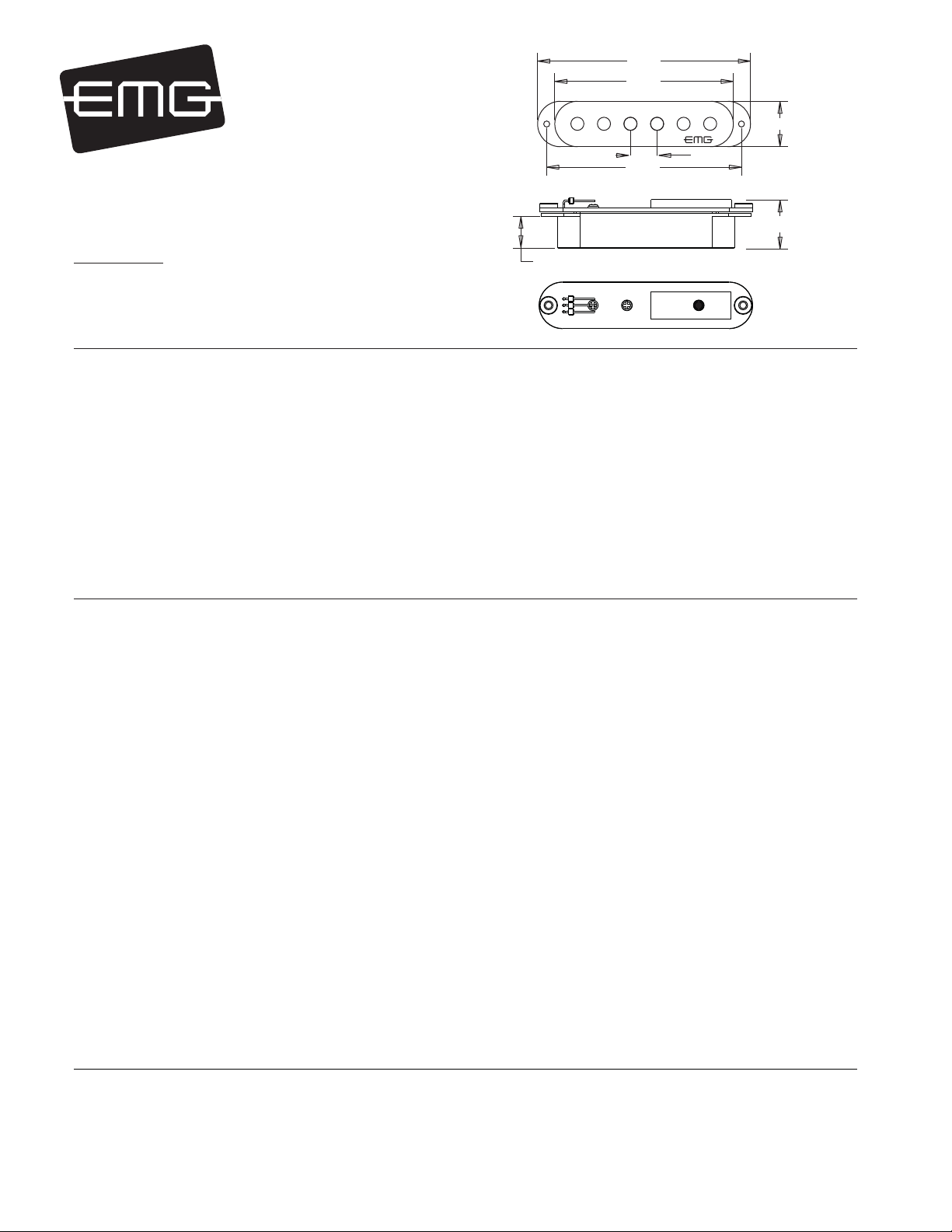
3.28
2.75
3.00
.70
6/32 MOUNTING SCREWS
.412 TYP
RA-Crossroads (A2)
RA-Maverick Five (A5)
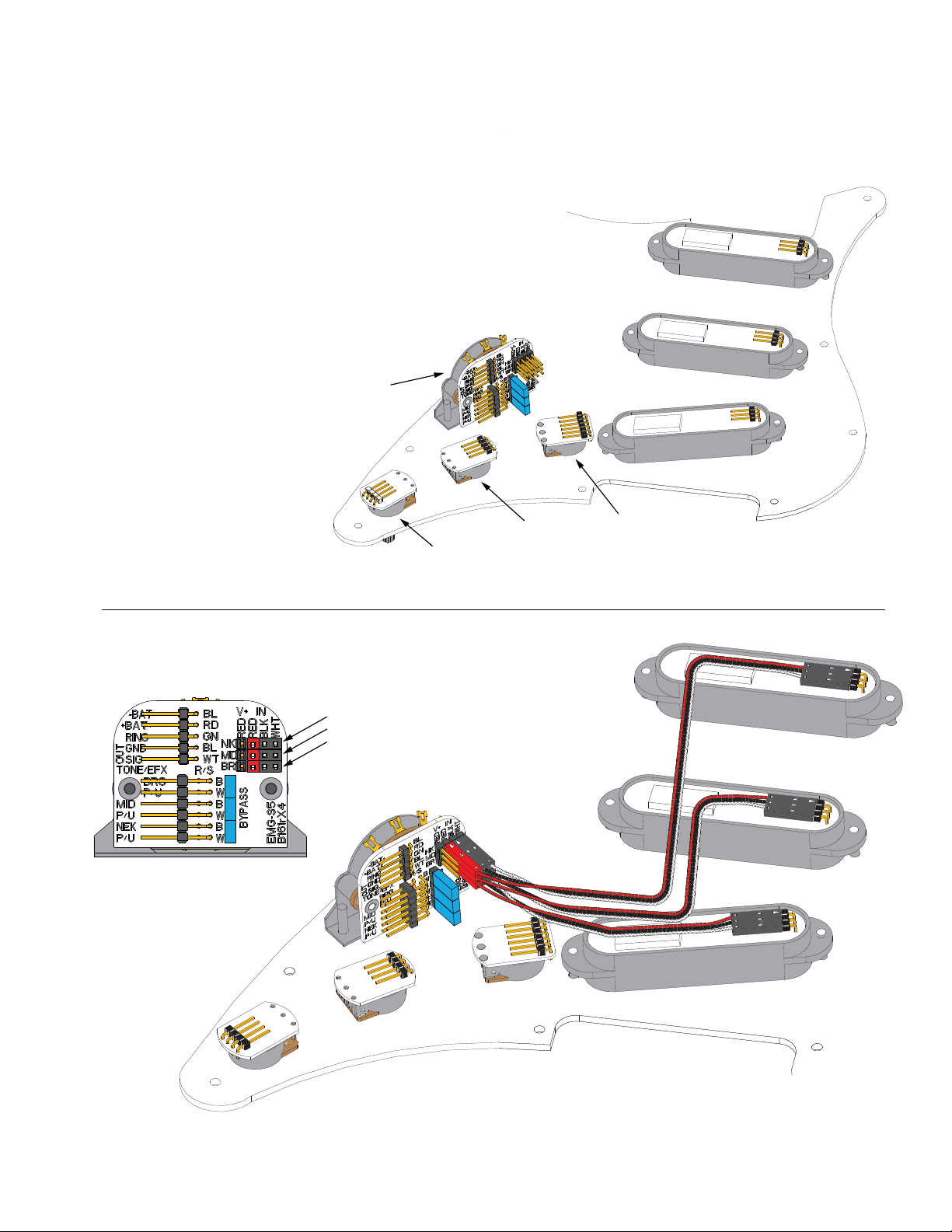
Installation notes:
All EMG Pickups are compatible with each other. The connector system is an easy method of installation, avoiding the need to solder.
Older systems may need to be soldered, while the newer systems can be easily connected and modified. If you have an older EMG
Pickup you can install the new system along with it.
EMG accessories like the VLPF, EXG, SPC or RPC Controls can be added to any EMG Pickup System without the need for an extra battery.
IMPORTANT INSTALLATION NOTES:
1) Only one 9-Volt battery is required to power the pickups and any
accessories such as the SPC, RPC, EXG, AB, PA-2, and Pi-2.
Use an Alkaline or Lithium battery for longest life.
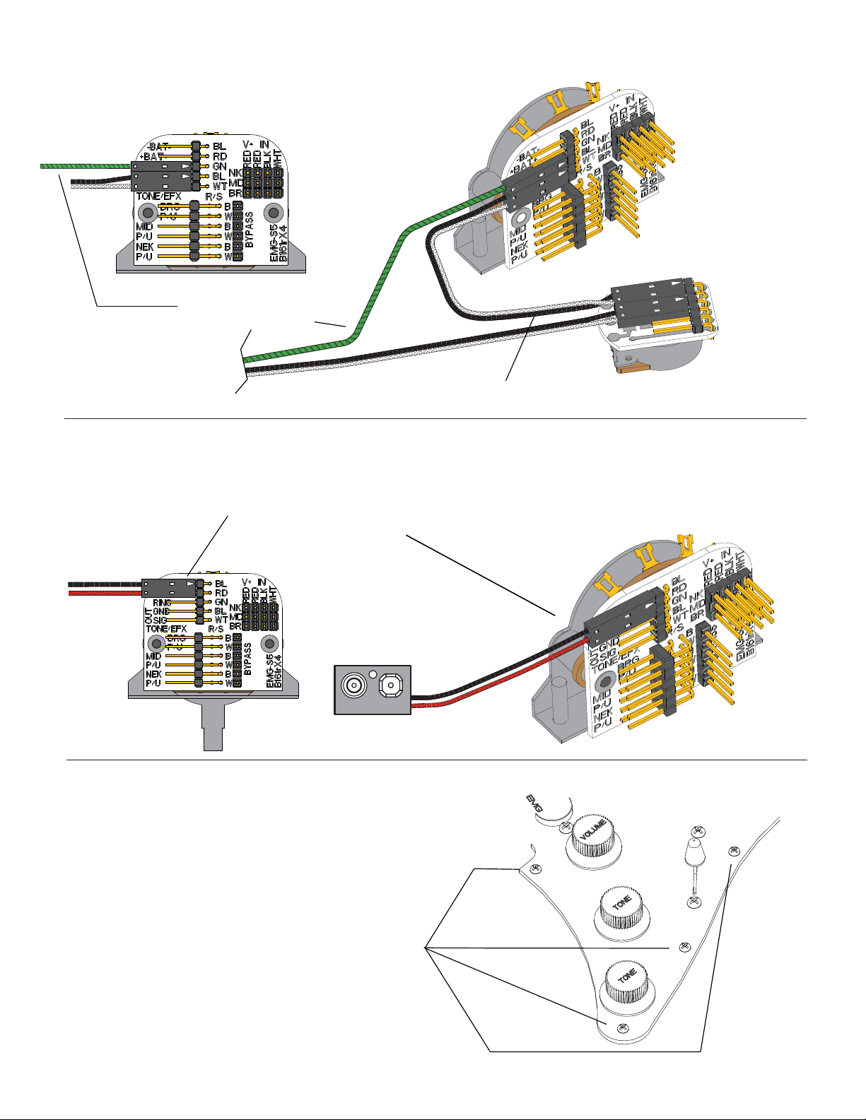
2) The Volume and Tone controls included with this EMG System are
25K Ohm. This value is required for the system to work correctly.
3) A stereo output jack (12B) is included with the EMG Pickups;
it grounds the black battery wire to turn on the pickups when
the plug is inserted into the jack. If you are replacing passive
pickups, make sure to use the jack included. If your guitar has a
long panel jack make sure it is a stereo type, a Switchcraft 152B
is recommended.
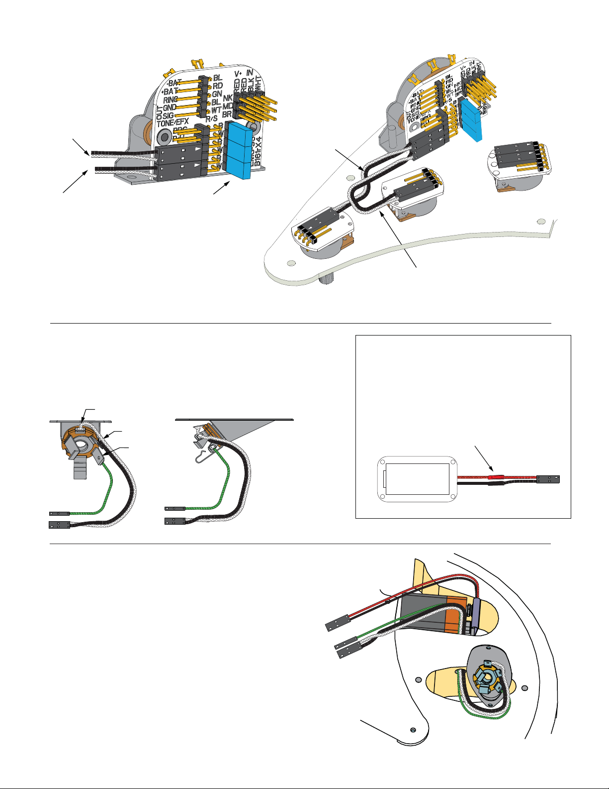
4) When installing EMG Active Pickups, DO NOT connect the bridge
ground wire. This wire is usually soldered to a volume or tone
control casing and goes to the bridge. This wire grounds the
strings and uses them and your body as a shield against hum and
buzz. It also creates a shock hazard.
EMG Pickups are shielded internally and DO NOT require string
grounding. This greatly reduces the possibility of reverse
polarity shock from microphones and other equipment.
5) EMG Active Pickups have very little magnetism compared to
passive pickups. We recommend you adjust the pickups as
close to the strings as possible. Sustain and string movement
will not be inhibited by close adjustment. Models EMG-SV,
EMG-SAV, and EMG-SLV feature magnetic pole pieces which can
inhibit intonation and string movement.
6) If your installation is different from the diagrams in these
instructions or you need additional diagrams visit our website:
emgpickups.com for a complete listing of available diagrams.
SPECIFICATIONS: MODEL
Maverick Five Set Crossroads Set
Logo Color Gold Gold Gold Gold Gold Gold
Magnet Type * A5 A5 A5 A2 A2 A2
Gauss Strength at Poles 750 750 750 600 600 600
Resonant Frequency (KHz) 4.75 3.50 3.00 4.50 3.30 2.90
Output Voltage (String) 1.00 1.00 1.00 1.00 1.00 1.00
Output Voltage (Strum) 3.00 3.00 3.00 3.00 3.00 3.00
Output Noise (60 Hz) -103 -103 -103 -103 -103 -103
Output Impedance (Kohm) 3 3 3 3 3 3
System Current @9V (Microamps) 630 630 630 630 630 630
System Battery Life (Hours) 830 830 830 830 830 830
Maximum Supply (Volts DC) 27 27 27 27 27 27
NECK MID BRIDGE NECK MID BRIDGE
.490 (12.44)
RED
BLK
WHT
EMG B315rA
.770 (19.5)
*Note: Magnet Type: A5 (Alnico 5) A2 (Alnico 2)
**Note: Specifications shown are for the entire 3 pickup system
TONE CONTROL
MIDDLE PICKUP
(PASSIVE)
TONE CONTROL
NECK PICKUP
(PASSIVE)
VOLUME CONTROL
(MASTER)
EMG-S5 (B161v4)
5 POSITION SWITCH
Retro Active S/S/S COMBINATION SYSTEM INSTRUCTIONS Page 2
Installation Instructions:
EMG-S/S/S Combination Systems
General Notes:
Every attempt has been made to make this a solderless installation.
There are some instances where this is not possible;
1) If your instrument uses the long panel output jack and you had passive pickups
you will need a new stereo output jack, the Switchcraft 152B is recommended.
Soldering to the new jack will be required, see the Power Tips Data sheet at
http://www.emgpickups.com.
2) Some instruments may already have a battery holder installed and in that case
soldering may be required, see page 3.
Installing EMG Combination Systems is very easy and is accomplished in a few steps.
The controls included have a 10 mm bushing height so they can be used either on a
pickguard, or body mount. The cable lengths are designed for a pickguard, so you
should make sure they are long enough if you are mounting the system into a body.
Longer cable lengths may be required.
Step One:
Mount the pickups onto the Pickguard, or in the guitar body.
Step Two:
Plug the pickup cables onto the pickups
and then onto the switch as shown.
NECK PICKUP
MIDDLE PICKUP
BRIDGE PICKUP
If the instrument has a Battery Holder:
If your instrument has a 9 or 18-Volt battery holder you can still
use the EMG Connectors to supply power to the pickups.
Simply cut and strip the wires from the battery clip provided.
Twist the wires together and use the shrink tubing included
to cover the connections. Soldering the wires is the preferred.
Cover these connections with the
shrink tubing provided.
To PC Board
9/18 VOLT
BATTERY
HOLDER
TO EMG-S5 SWITCH
RING
TIP
SLEEVE
Retro Active S/S/S COMBINATION SYSTEM INSTRUCTIONS Page 3
Step Four:
The Pickguard is now fully assembled. Next the pre-wired output jack
needs to be mounted in the Jack plate. Mount the Jack onto the plate
with the orientation as shown with the Tip spring pointing down.
Refer to the diagrams below and make sure the Jack is mounted tightly.
Step Five:
Route the Output cable from the Jack cavity into the control cavity via the small hole.
If the hole is too small, Push the connectors through one at a time.
Fasten the Jack plate onto the guitar and test to make sure the cable inserts and exits easily.
Mount the battery in the control compartment. Insulate the battery using
the foam insulator provided..
Step Three:
1) Start by installing the SEND cables onto the outer
(furthest from the PC Board) 6-pin header labeled “S”.
Plug in one cable for the Neck Pickup tone control
and one cable for the Middle Pickup Tone control.
Step Three:
Plug the Volume and Tone control cables onto the controls
and then onto the switch as shown.
TO MIDDLE PICKUP
TONE CONTROL
TO NECK PICKUP
TONE CONTROL
MIDDLE PICKUP
TONE CABLE
NECK PICKUP
TONE CABLE
SEND
SEND
SEND
SEND
INSTALL ALL 3 BLUE SHUNTS
ON THE BYPASS HEADER
Battery Replacement:
Remove these 4 screws,
gently lift the pickguard’
remove and replace the battery.
Step Eight:
This completes the installation. Plug the battery clip onto the battery.
We suggest you plug in the instrument, tap lightly on the pickups with
a small screwdriver to make sure the pickups are working correctly.
When the battery needs to be replaced (about 6 months to 1 year)
refer to the diagram at the right.
Retro Active S/S/S COMBINATION SYSTEM INSTRUCTIONS Page 4
Step Six:
1) Plug the Output Cable from the PC Board (GND/SIG) to the Volume Control.
2) Plug the Output cable from the Output Jack onto the Volume control as shown.
3) Plug the green wire onto the Ring terminal of the Switch PC Board.
Step Seven:
Plug the Battery clip cable onto the BAT- (BLACK) and the BAT+ (RED)
terminals of the PC Board.
OUTPUT CABLE TO THE VOLUME CONTROL
GREEN WIRE TO THE RING
TERMINAL PIN OF THE PC BOARD
FROM
OUTPUT JACK
BATTERY CLIP TO BAT- AND BAT+
TERMINALS ON THE PC BOARD
- 9V +

This manual suits for next models

2

Other EMG Musical Instrument manuals

EMG KH-20 Service manual

EMG

EMG KH-20 Service manual

EMG TBP Service manual

EMG

EMG TBP Service manual

EMG MM5TW Service manual

EMG

EMG MM5TW Service manual

EMG EMG-89 User manual

EMG

EMG EMG-89 User manual

EMG P-HZ Service manual

EMG

EMG P-HZ Service manual

EMG VG-20 Service manual

EMG

EMG VG-20 Service manual

EMG 40J Service manual

EMG

EMG 40J Service manual

EMG PRO SL-20 Service manual

EMG

EMG PRO SL-20 Service manual

Popular Musical Instrument manuals by other brands

Viscount Chorale 8 user manual

Viscount

Viscount Chorale 8 user manual

Johannus One user manual

Johannus

Johannus One user manual

Casio Privia PX-350M user guide

Casio

Casio Privia PX-350M user guide

Roland C-190 user manual

Roland

Roland C-190 user manual

MEINL MYO-BCAJ Assembly instructions

MEINL

MEINL MYO-BCAJ Assembly instructions

Roland FR-7/FR-5 owner's manual

Roland

Roland FR-7/FR-5 owner's manual

Yamaha Clavinova CVP-205 Service manual

Yamaha

Yamaha Clavinova CVP-205 Service manual

Roland RD-500 owner's manual

Roland

Roland RD-500 owner's manual

Kawai KCP90 owner's manual

Kawai

Kawai KCP90 owner's manual

DVS Clipster Hardware guide

DVS

DVS Clipster Hardware guide

Hohner Symphonic 33 General servicing instructions

Hohner

Hohner Symphonic 33 General servicing instructions

Yamaha MIDI Rocker LX user guide

Yamaha

Yamaha MIDI Rocker LX user guide

midiplus EASY PIANO owner's manual

midiplus

midiplus EASY PIANO owner's manual

StudioDesk Pro Line M Series Assembly manual

StudioDesk

StudioDesk Pro Line M Series Assembly manual

Yamaha Arius YDP-140 owner's manual

Yamaha

Yamaha Arius YDP-140 owner's manual

Guild T-Bird S-200 user guide

Guild

Guild T-Bird S-200 user guide

Gear4music Guitarworks 175957 manual

Gear4music

Gear4music Guitarworks 175957 manual

Dream Cheeky iPlay Piano instructions

Dream Cheeky

Dream Cheeky iPlay Piano instructions

manuals.online logo
manuals.online logoBrands
  • About & Mission
  • Contact us
  • Privacy Policy
  • Terms and Conditions

Copyright 2025 Manuals.Online. All Rights Reserved.