Emheater EM15-SP Series User manual


Preface
Thank you for purchasing the EM15-SP series solar inverter developed by China EM Technology Limited.
Features:
⚫MPPT algorithm of fast tracking of maximum power point of PV cells, efficiency >99%.
⚫Solar battery working point voltage can be manually or automatically MPPT tracking.
⚫All weather automatic operation,can also be manually or automatically,
⚫Realize”sunrise work and sunset sleep”.
⚫35 kinds protection function. including auto detecting short circuit after power on.
⚫Auto sleep function/pump dry protect/low frequency protection/over load protection and etc.
⚫Full protections:overload,over current, overvoltage,under voltage,short circuit, dry pumping etc.
⚫Output frequency range: V/F(0~3000hz); vector control(0~300HZ).
⚫Overload capacity:60s with 150% of rated current,3s with 180% of rated current.
⚫Speed accuracy:±0.5%(SVC);±0.02%(VC).
⚫Pulse setting input:0Khz~100Khz.
⚫Remote control, support RS232/RS485 protocol, terminal control, analog control.
Before unpacking, please check carefully:
1. Whether the nameplate model of solar inverter are consistent with your order ratings. The box contains the solar
inverter, user manual.
2. Whether the solar inverter is damaged during transportation. If you find any omission or damage, please contact
us or your local supplier immediately.
First-time Use
For the users who use this product for the first time, read the manual carefully. If in doubt concerning some
functions or performances, contact the technical support personnel to ensure correct use.
Due to the continuous improvement of solar inverter, this document will be updated without prior notice.
EM15-SP series solar inverter complies with the following international standards. All products have passed the CE
certification.
IEC/EN61800-5-1: 2003 Variable speed electric drive system safety requirements;
IEC/EN61800-3: 2004 Variable speed electric drive system, Part 3: The Electro Magnetic Compatibility (EMC)
Standards of Product and its specific testing methods.
Version:V2.0.0

Contents
1. Safety Information and Precautions......................................................................................................................... 1
1.1 Safety Information......................................................................................................................................... 1
2. Product Information................................................................................................................................................. 3
2.1 Designation Rules.......................................................................................................................................... 3
2.2 Model and Technical Data............................................................................................................................. 3
2.3 ProductAppearance and Installation Dimension........................................................................................... 4
2.3.1 ProductAppearance............................................................................................................................ 4
2.3.2Appearance and Installing Dimension................................................................................................ 4
2.3.3 Installation Dimension of External Keypad (Keypad Tray) ............................................................... 5
3.Installation of Frequency Inverter............................................................................................................................. 6
3.1 Installation Environment ............................................................................................................................... 6
3.2 Installation Direction and Space.................................................................................................................... 6
3.3 Sketch and Description of Main Circuit Terminals........................................................................................ 7
3.3.1 Function and Description of Main Circuit Terminals......................................................................... 7
3.4 Control Circuit and Main Circuit Terminals Description .............................................................................. 8
3.4.1 Control Circuit and Main Circuit Wiring............................................................................................ 8
3.4.2 Control Circuit Terminal Layout......................................................................................................... 8
3.4.3 Description of Control Circuit Terminals ........................................................................................... 8
3.5 Collection Diagram For Different Motor..................................................................................................... 10
3.5.1 The Wiring of Water-Level Automatic Control .................................................................................11
4 Operation and Display............................................................................................................................................ 13
4.1 Instruction of Operation and Display........................................................................................................... 13
4.2 Function Code Table.................................................................................................................................... 14
5. Fault Diagnosis and Solution................................................................................................................................. 42
5.1 FaultAlarm and Countermeasures............................................................................................................... 42
Appendix I. Modbus Communication Protocol......................................................................................................... 44
I. About Protocol................................................................................................................................................ 44
II. Application Methods..................................................................................................................................... 44
III. Bus Structure ............................................................................................................................................... 44

EM15-SP User Manual 1. Safety Information and Precautions
1
1. Safety Information and Precautions
In this manual, the notices are graded based on the degree of danger:
Danger: Indicates that failure to comply with the notice will result in severe personal injury or even death.
Warning: Indicates that failure to comply with the notice will result in personal injury or property damage.
Read this manual carefully so that you have a thorough understanding. Installation, commissioning or maintenance
may be performed in conjunction with this chapter. EMHEATER will assume no liability or responsibility for any
injury or loss caused by improper operation.
1.1 Safety Information
Danger
⚫Do not use damaged or missing components solar inverter. Failure to comply will result in personal injury.
⚫Please use the electric motor with upper B insulation class. Failure to comply will result in personal injury.
⚫Install the solar inverter on incombustible objects such as metal, and keep it away from combustible materials.
Failure to comply may result in a fire.
⚫Wiring must be performed only by qualified personnel under instructions described in this manual. Failure to
comply may result in unexpected accidents.
⚫A circuit breaker must be used to isolate the power supply and the solar inverter. Failure to comply may result
in a fire.
⚫Ensure that the power supply is cut off before wiring. Failure to comply may result in electric shock.
⚫Connect the solar inverter to ground properly by standard. Failure to comply may result in electric shock.
⚫Cover the solar inverter properly before power-on to prevent electric shock.
⚫Do not open the solar inverter’s cover after power-on to prevent from electric shock.
⚫Do not touch the solar inverter with wet hand and its peripheral circuit to prevent from electric shock.
⚫Do not touch the terminals of the solar inverter (including the control terminals). Failure to comply may result
in electric shock.
⚫Do not touch the U, V, W terminal or motor connecting terminals when solar inverter automatically does
safety testing for the external high-voltage electrical circuit. Failure to comply may result in electric shock.
⚫Do not go close to the equipment when selected the restart function. Failure to comply may result in personal
injury.
⚫Do not touch the fan or the discharging resistor to check the temperature. Failure to comply will result in
personal injury.
⚫Signal detection must be performed only by qualified personal during operation

1. Safety Information and Precautions EM15-SP User Manual
2
Warning:
⚫When two solar inverters are laid in the same cabinet, arrange the installation positions properly to ensure the
enough cooling effect.
⚫Do not drop wire residue or screw into the solar inverter. Failure to comply will result in damage to the solar
inverter.
⚫Never connect the power supply cables to the output terminals (U, V, W) of the solar inverter. Failure to
comply will result in damage to the solar inverter.
⚫Make sure that all the connecting wires comply with the requirement of EMC and the safety standard in the
region. Use wire sizes recommended in the manual. Failure to comply may result in accidents.
⚫Never connect the braking resistor between the DC bus terminals (P+) and (P-). Failure to comply may result
in a fire.
⚫Do not perform the voltage resistance test on any part of the solar inverter because such test has been done in
the factory. Failure to comply will result in accidents.
⚫All peripheral devices must be connected properly under the instructions described in this manual. Failure to
comply will result in accidents.
⚫Note the danger during the rotary running of motor when check the parameters. Failure to comply will result
in accidents.
⚫Do not change the factory default settings of the solar inverter. Failure to comply will result in damage to the
solar inverter.
⚫Avoid objects falling into the solar inverter when it is running. Failure to comply will result in damage to solar
inverter.
⚫Do not start/stop the solar inverter by turning the contactor ON/OFF. Failure to comply will result in damage
to the solar inverter.

EM15-SP User Manual 2. Product Information
3
2. Product Information
2.1 Designation Rules
EM15 Series Frequency Inverter
Products Type: PV use
Voltage range:
1: DC 250~400V to Three phase AC 220V
3: DC 350~750V to Three phase AC 380V
Adaptable motor: 7d5: 7.5KW ;011: 11KW
Diagram 2-1 Designation rules
2.2 Model and Technical Data
Table 2-1EM15-SP Model and technical data
EM15-SP1
Description
d75
1d5
2d2
004
5d5
7d5
011
015
018
022
030
037
045
DC input (+, -)
Rated power/KW
0.75
1.5
2.2
4
5.5
7.5
11
15
18.5
22
30
37
45
Min. DC voltage/V
120
Max.DC voltage/V
400
Recommended MPPT
range /V
250~400
AC output(U, V, W)
Output current/A
3.8
5.1
9
13
25
32
45
60
75
91
112
150
176
EM15-SP3
Description
d75
1d5
2d2
004
5d5
7d5
011
015
018
022
030
037
045
055
075
090
110
132
160
200
220
250
280
315
355
400
DC input (+, -)
Rated power/KW
0.75
1.5
2.2
4
5.5
7.5
11
15
18.5
22
30
37
45
55
75
90
110
132
160
200
220
250
280
315
355
400
Min. DC voltage/V
280
Max.DC voltage/V
750
Recommended MPPT
range /V
350~750
AC output(U, V, W)
Output current
2.1
3.8
5.1
9
13
17
25
32
37
45
60
75
91
112
150
176
210
253
304
377
426
465
520
585
650
725
Output frequency
0~50/60Hz
Power factor
>0.99
Communication mode
RS485 communication
Protection class
IP20
Ambient temperature
-10℃~ +40℃(ambient temperation at 40℃~50℃,please keep derated use)
Storage temperature
-20℃~ +60℃
Humidity
Smaller than 95%RH, non-condensation
Cooling
Forced Air cooling
Altitude
Lower than 1000 m
Humidity
Less than 95%RH, without condensing
Vibration
Less than 5.9 m/s2 (0.6 g)
2. Product Information EM15-SP User Manual
4
2.3 Product Appearance and Installation Dimension
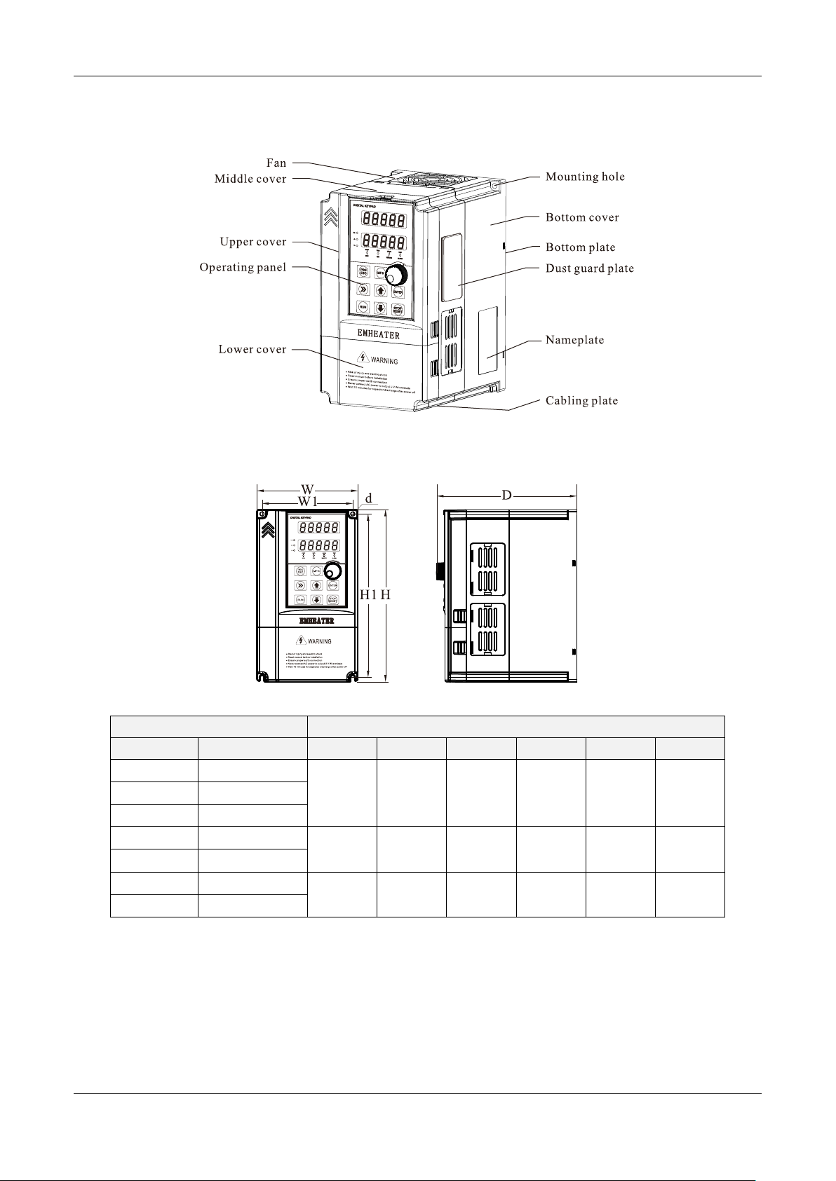
2.3.1 ProductAppearance
Diagram 2-2 Product appearance (With potentiometer)
2.3.2Appearance and Installing Dimension
Diagram 2-3 Appearance and installation dimension of EM15 series (Plastic housing structure)
Matching inverter
Appearance and installing dimension (Unit: mm)
Voltege
Power Range
W
W1
H
H1
D
d
1PH 220V
0.75~2.2kW
120
108
205
195
166
Φ4.5
3PH 220V
0.75~2.2kW
3PH 380V
4~5.5kW
3PH 220V
4~5.5kW
162
148
250
238
191
Φ5.5
3PH 380V
7.5~11kW
3PH 220V
7.5~11kW
223
207
323
307
207
Φ5.5
3PH 380V
15~22kW

EM15-SP User Manual 2. Product Information
5
Diagram 2-4 Appearance and installation dimension of EM15 series (Metal housing structure)
Matching inverter
Appearance and installing dimension (Unit: mm)
Voltege
Power Range
W
W1
H
H1
D
d
3PH 220V
15~18.5kW
300
220
540
500
240
Φ7
3PH 380V
30~37kW
3PH 220V
22kW
340
260
580
540
270
Φ10
3PH 380V
45~55kW
3PH 220V
37~45KW
410
260
610
575
280
Φ12
3PH 380V
75~90kW
3PH 380V
110~132kW
460
320
710
690
335
Φ12
3PH 380V
160~220kW
535
360
885
830
370
Φ12
3PH 380V
250~315kW
650
360
1040
985
415
Φ12
3PH 380V
355~400kW
815
600
1350
1250
445
Φ12
2.3.3 Installation Dimension of External Keypad (Keypad Tray)
Diagram 2-5 Appearance and installation dimension of external keypad (keypad tray)

3. Installation of Frequency Inverter EM15-SP User Manual
6
3.Installation of Frequency Inverter
3.1 Installation Environment
1. The place with indoor vents or ventilation devices.
2. The environment temperature shall be -10℃~40℃. If the temperature is over 40℃but less than 50℃,
better to take down the cover of frequency inverter or open the front door of cabinet to facilitate heat
dissipation.
3. Try to avoid high temperature and wet place; the humidity shall be less than 90% without frost deposit.
4. Avoid direct sunlight.
5. Keep away from flammable, explosive and corrosive gas and liquid.
6. No dust, floating fiber and metal particles.
7. Install on the place without strongly vibration. And the vibration should be not over 0.6G, Especially
pay attention to far away from the punching machine, etc.
8. Keep away from electromagnetic interference source.
3.2 Installation Direction and Space
In order to not affect the service life of frequency inverter and reduce its performance, note for its
installation direction and space and correctly fasten it.
Diagram3-1 Ventilating duct installation dimension diagram of frequency inverter
Power class
Installation dimension
A
B
≤7.5kW
≥ 20mm
≥ 100mm
11kW - 30kW
≥ 50mm
≥ 200mm
≥ 37kW
≥ 50mm
≥ 300mm
Please install the frequency inverter vertically, to send out the heat upward, and pay attention to direction of
frequency inverter to avoid inversion.
If there are several units of frequency inverter installed, please install them side by side, do not to install up
and down.
EM15-SP User Manual 3. Installation of Frequency Inverter
7
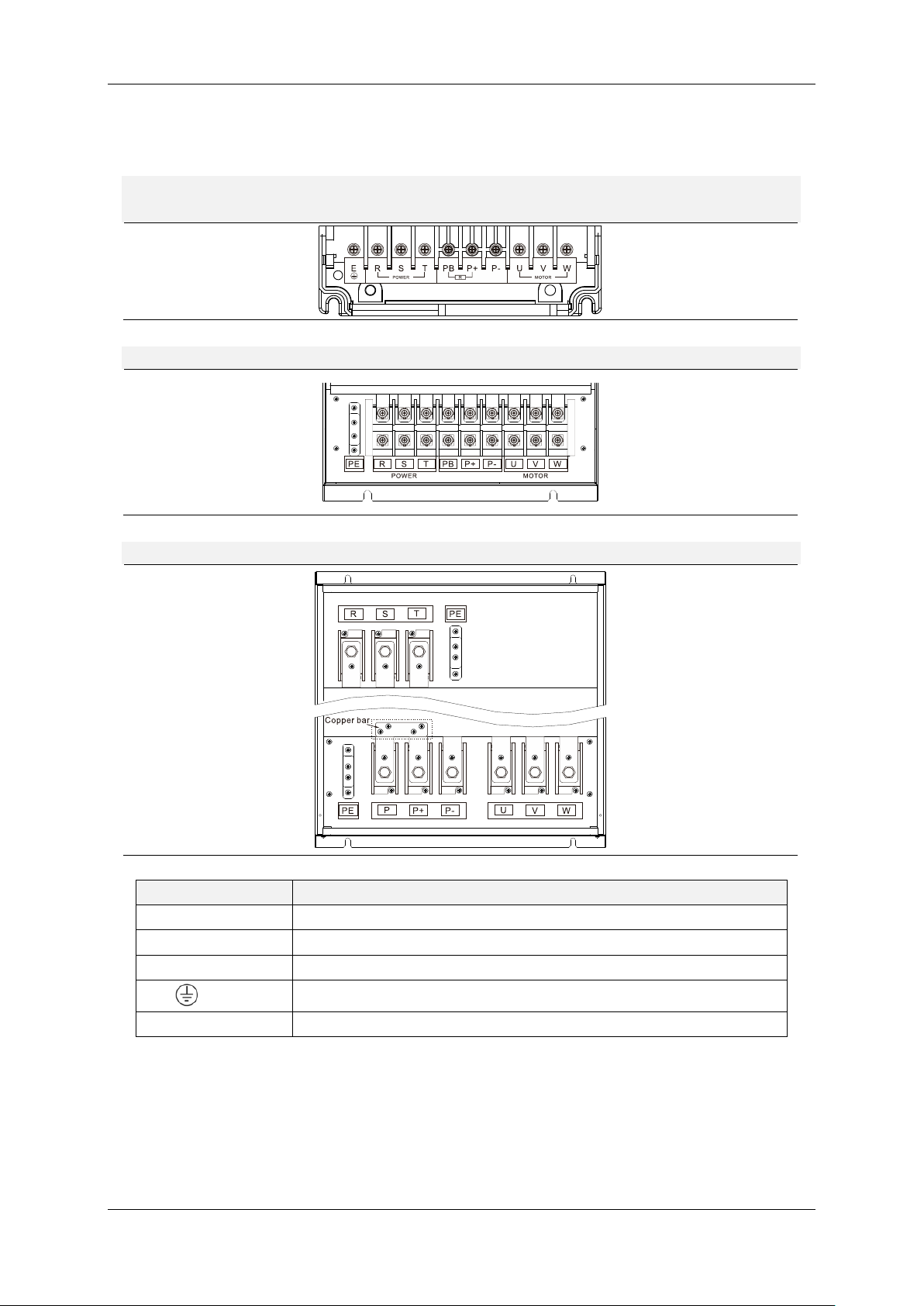
3.3 Sketch and Description of Main Circuit Terminals
3.3.1 Function and Description of Main Circuit Terminals
Three phase 220V output:EM15-SP1-d75~EM15-SP1-011
Three phase 380V output:EM15-SP3-d75~EM15-SP3-022
Three phase 380V output:EM15-SP3-030~EM15-SP3-090
Three phase 380V output:EM15-SP3-110~EM15-SP3-400
Terminal symbol
Function description
R, S, T
AC power input terminals
P+,PB
Braking resistor connectin
P+,P-
DC power input terminals
or E/PE
Grounding terminal
U,V,W
Three-phase AC power output terminals

3. Installation of Frequency Inverter EM15-SP User Manual
8
3.4 Control Circuit and Main Circuit Terminals Description
3.4.1 Control Circuit and Main Circuit Wiring
Diagram3-2 EM15-SP control circuit and main circuit wiring
3.4.2 Control Circuit Terminal Layout
Diagram3-3 EM15-SP control circuit terminal sketch diagram
3.4.3 Description of Control Circuit Terminals
Type
Terminal
Symbol
Terminal Name
Terminal function description
Power
Supply
+10V-GND
External +10V
power supply
Provide +10V power supply to external unit. Maximum
output current:10Ma
Generally, it provides power supply to external potentiometer
with resistance range of 1 kΩ~5kΩ
+24V-COM
External +24V
power supply
Provide +24 V power supply to external unit. Generally, it
provides power supply to DI/DO terminals and external
sensors.Maximum output current: 200 mA

EM15-SP User Manual 3. Installation of Frequency Inverter
9
Type
Terminal
Symbol
Terminal Name
Terminal function description
PLC
External power
supply input
terminals
It connect with +24V default
Analog
input
AI1-GND
Analog input 1
1. Input range: DC 0V~10V/ 0mA~20mA(decided by jumper
AI1/AI2 on the control board); AI3: DC -10V~+10V
2. Impedance: 22 kΩ (voltage input), 500 Ω (current input)
AI2-GND
Analog input 2
AI3-GND
Analog input 3
Digital
input
DI1-COM
Digital input 1
1. Optical coupling isolation, compatible with dual polarity
input
2.Input Impedance: 2.4 kΩ
3. Voltage range for level input: 9V~30 V
DI2-COM
Digital input 2
DI3-COM
Digital input 3
DI4-COM
Digital input 4
DI5-COM
Digital input 5
HDI-COM
High Speed
Pulse Input
Maximum input frequency: 100 kHz
Analog
output
AO1-GND
Analog output
1
Voltage or current output is decided by jumper AO1/AO2.
Output voltage range: 0V~10 V
Output current range: 0mA~20 mA
AO2-GND
Analog output
2
FMP- COM
High Speed
Pulse Output
Constrained by function code b4-00 "FMP terminal output
mode selection" as the high-speed pulse output, the highest
frequency is 100kHz; when use as an open collector output,
specifications is the same as DO.
Relay
output
TA1-TB1
NC terminal
Contact driving capacity: 250 VAC, 3 A, COSø= 0.4
DC 30 V, 1 A
TA2-TB2
TA1-TC1
NO terminal
TA2-TC2
RS485
Output
485+
Communication
port terminal
Input and output signal terminals for MODBUS protocol
communication
485-
Auxiliary
interface
PG card interface
PG cards: Open-collector, differential are selectable options.
Communications expansion
Reversed
External keypad interface
Connected to an external keypad
Jumper
PE-COM
COM grounding PE selection ,default connection.
In the case of interference, connecting PE to COM can improve
anti-interference
PE-GND
GND grounding PE selection ,default connection.
In the case of interference, connecting PE to COM can improve
anti-interference.
AI1
AI1 output selection.
Voltage or Current output, voltage output by default.
AI2
AI2 output selection.
Voltage or Current output, current output by default.
AO1/AO2
AO1/AO2 output selection.
Voltage or Current output, voltage output by default.
458
485 communication resistor selection, default connection
ON.
In the case of interference, anti-interference can be improved.

3. Installation of Frequency Inverter EM15-SP User Manual
10
3.5 Collection Diagram For Different Motor
COM
Photovoltaic cell
Water Tank
Pump
Water Pipe
+-UV W
EM15-SP
Control Term inal
DI1 DI2
Note: For the EM15-SP1S series,
U and V as single Phase 220V
output terminal.
Diagram3-4 220V three phase installed without water level sensor (PV Input)
COM
Control Term inal
Water Tank
Pump
Water Pipe
Photovoltaic cell
+-UV W
EM15-SP
DI1 DI2 DI4 DI5
Diagram3-5 Diagram of 3phsae inverter connection method (PV Input)

EM15-SP User Manual 3. Installation of Frequency Inverter
11
3.5.1 The Wiring of Water-LevelAutomatic Control
The wiring for floater water-level switch connected by cable
The common port, which using floate water-level switch connected by cable, is fed to the terminal “COM”
of EM15-SP.And then, connected to DI1.
DI1
COM
EM15-SP
Inverter
DI1
COM
EM15-SP
Inverter
High water-level
Low water-level
Diagram3-6 Diagram of Low water level and high water level
Remarks:
When the actual water-level in the wells is higher than the horizontal line of high water-level, DI1 will be
connected to the “COM”as well as controller automatically will start the pump. On the contrary, if the
actual water-level is lower than the horizontal line of low water-level, DI1 will be disconnected from
“COM”as well as controller automatically stop the pump to prevent anhydrous idling.
The wiring for floater water-level switch mounted on a side
The floater water-level switch mounted on a side is the normally open contact to output and its common
wire is connected to the terminal COM of EM15-SP inverter. At the same time, the low level-water wire is
connected to terminal DI4 and the high water-level wire is connected the terminal DI5.
EM15-SP
EM15-SP
EM15-SP
EM15-SP
DI5
Low water-level
High water-level
COM DI5 COM
DI4 COM DI4 COM
Detector switch of
high water-level
Detector switch of
low water-level
Detector switch of
high water-level
Detector switch of
low water-level
Diagram3-7 Diagram of Low water level and high water level

3. Installation of Frequency Inverter EM15-SP User Manual
12
Remarks:
When the actual water-level in the reservoir is lower than horizontal line of low water-level, DI4 and DI5
will be disconnected from the COM as well as controller automatically strat the pum. On the contrary, if the
actual water-level is higher than the horizontal line of high water-level, DI4 and DI5 will be connected to
COM as well as controller automatically stop the pump to prevent water overflow.
Notice:
1. If only use one detection signal of water-level in the reservoir, DI4 and DI5 must be connected together
by conductor.
EM15-SP User Manual 4. Operation and Display
13
4 Operation and Display
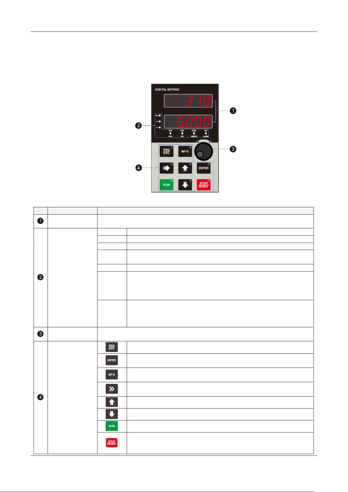
4.1 Instruction of Operation and Display
Diagram 4-1 Operating panel
No.
Name
Function
LED display area
The 5-digit LED display is able to display the set frequency, output frequency, monitoring
data and fault codes.
Unit / Status
Indicator area
Hz
Frequency unit
A
Current unit
V
Voltage unit
STOP/
RUN
OFF indicates that the frequency inverter is in the stop state and ON indicates
that the frequency inverter is in the running state.
FWD/REV
It is Forward/Reversal indicator, ON indicates Reverse rotation.
LOCAL
/REMOTE
It indicates whether the frequency inverter is operated by operation keypad,
terminals or remoter (communication). OFF indicates keypad operation
control state; ON indicates terminals operation control state; Blinking
indicates remote operation control state.
TRIP
/ALARM
Tunning/ Torque Control/Fault indicator
When the indicator is ON, it indicates torque control mode. When the
indicator is blinking slowly, it indicates the auto-tuning state. When the
indicator is blinking quickly, it indicates the fault state.
Encoder knob
Frequency, data or function code increase or decrease; the encoder knob has the
confirmation key function
Operation key area
Programming key: Enter or exit menu level I.
Confirmation key: Enter the menu interfaces level by level, and confirm the
parameter setting.
Multi-function key: Perform function switchover according to the setting of
b9-01
Shift key: Select the displayed parameters in turn in the stop or running
state, and select the digit to be modified when modifying parameters.
Increment key: Increase data or function code.
Decrement key: Decrease data or function code.
Running key: Start the frequency inverter in the keypad control mode.
Stop/Reset key: Stop the frequency inverter when it is in the running state and
perform the reset operation when it is in the fault state. The functions of this
key are restricted by b9-00.

4. Operation and Display EM15-SP User Manual
14
4.2 Function Code Table
Debugging specification:
1. Set A1-00 to turn on photovoltaic mode, or it’ll run in ordinary inverter mode; Set A1-01 to enable MPPT function to
search Vmpp voltage automatically; Otherwise, the default Vmpp voltage needs to be set manually;
2. Target frequency is the maximum frequency limit, and MPPT automatically controls the operating frequency and
searches for the maximum operating frequency;
3. Stability parameters A1-13, A1-14: Adjust to the stable state of bus voltage, output frequency and output current
(normal small fluctuation);
4. Light intensity detection:
5. Other protection functions: dormancy and underload
6. The operation direction of the pump is limited. If there is no water coming out, the motor wiring can be adjusted or
b0.18 can be set to change the direction;
7. Relevant Settings of A1-04, sleeping voltage, etc. should be made according to the configuration of the panel. Default
parameters are suitable for working near 500V DC voltage;
8. Power on automatic operation:
Group A1: PV Special Control Parameters
Code
Parameter Name
Functional description
Default
Property
A1-00
PV mode enable
0: Disabled
1: Enabled
1
★
A1-01
Vmpp voltage Selection
0: Manual setting
1: MPPTAutomatic algorithm tracking
1
★
A1-02
Vmpp voltage value of
manual given
0~100.0%
85.00%
★
A1-03
PV open circuit voltage
selection
0: Automatic detection of shutdown
1: Manual setting
0
★
A1-04
PV open circuit voltage
manual setting value
0.0~1000.0V
500.0V
★
A1-05
MPPT interval
0.1~100.0s
1.0s
★
A1-06
MPPT hysteresis
0.01Hz~5.00Hz
0.10Hz
★
A1-07
MPPT step size
0.01%~10.00%
0.10%
★
A1-08
MPPT voltage upper limit
0.0~100.0%
100.0%
★
A1-09
MPPT voltage lower limit
0.0~100.0%
60.0%
★
A1-10
CVT proportional gain
0.00~20.00
0.50
★
A1-11
CVT integral coefficient
0.00~20.00
0.50
★
A1-12
CVT proportional gain 1
0.00~20.00
1.00
★
A1-13
CVT integral coefficient 1
0.00~20.00
1.00
★
A1-14
CVT switching point
3.0%~15.0%
5.0
★
A1-15
Open circuit reference
voltage
0.0~6553.5V
0.0V
★
A1-16
PV DC current
0.00~655.35A
0.00A
★
A1-17
PV DC current gain
0.0~200.0%
100.0%
★
A1-18
PV DC current bias
-100.00~100.00A
0.00A
★
A1-19
Sleep voltage
0.0~1000.0V
360.0V
★
A1-20
Wake-up voltage
0.0~1000.0V
400.0V
★
A1-21
Wake up time
0~30000s
60s
★
A1-22
Light weak detection
frequency
0.00~100.00Hz
15.00Hz
★

EM15-SP User Manual 4. Operation and Display
15
Code
Parameter Name
Functional description
Default
Property
A1-23
Low light sleep delay
0~30000s
30s
★
A1-24
Light weak wake-up time
0~30000s
60s
★
A1-25
Underload detection current
0.00~300.00A
0.00A
★
A1-26
Underload detection time
0~30000s
60s
★
A1-27
Underload reset delay
0~30000s
300s
★
A1-28
Water full delay time
0~30000s
60s
★
A1-38
Water full reset time
0~30000s
120s
★
A1-39
Water shortage delay time
0~30000s
60s
★
A1-40
Water shortage reset time
0~30000s
600s
★
A1-41
MPPT selection
0: Method 1
1: Method 2
2: Method 3
1
★
Alarm Stop Code
A-LP
Low-voltage sleep
Lower than value of A1-09, will give Low-voltage sleep alarm
A-LS
Light dormancy
Meet the conditions of A1-22/23, give light dormancy alarm
A-LL1
Underload protection
Meet the conditions of A1-25/26, give Underload protection alarm
A-TF
Full protection
Define DI terminal to 52, enable ON
A-LL
Water shortage protection
Define DI terminal to 53, enable ON
Group b0: Basic Function Parameters
Code
Parameter Name
Functional description
Default
Property
b0-01
Motor control mode
0: Sensor-less vector control (SVC)
1/2:V/F control
3: Closed-loop vector control (FVC)
2
★
b0-02
Command source selection
0: Keypad control (LED off)
1: Terminal control (LED on)
2: Communication control (LED blinking)
0
★
b0-03
Main frequency source X
selection
0: Digital setting (Digital setting frequency b0-12,
UP/DOWN modifiable, no-record after power off)
1: Digital setting (Digital setting frequency b0-12,
UP/DOWN modifiable, record after power off)
2: AI1
3: AI2
4: AI3
5: Pulse setting (HDI)
6: Multi-function
7:Built-in PLC
8: PID
9: Communication setting
1
★
b0-04
Auxiliary frequency source
Y selection
The same as b0-03 (Main frequency source X selection)
0
★
b0-05
Selection of auxiliary
frequency Y range
0: Relative to maximum frequency
1: Relative to main frequency X
0
☆
b0-06
Range of auxiliary
frequency Y
0%~150%
100%
☆

4. Operation and Display EM15-SP User Manual
16
Code
Parameter Name
Functional description
Default
Property
b0-07
Frequency source selection
Unit's digit: Frequency source selection.
0: Main frequency source X
1: X and Y calculation (calculation result determined by
ten's digit)
2: Switchover between X and Y
3: Switchover between X and "X and Y calculation"
4: Switchover between Y and "X and Y calculation"
Ten's digit: X and Y calculation relationship
0: X+Y
1: X-Y
2: Maximum of them
3: Minimum of them
0
☆
b0-08
Encoder knob frequency
change unit
0:1Hz
1:0.1Hz
2:0.2Hz
0
☆
b0-09
Binding command source to
frequency source
Unit's digit: Binding keypad command to following
frequency source.
0: No binding
1: Digital setting frequency
2: AI1
3: AI2
4: AI3
5: Pulse setting (HDI)
6: Multi-function
7: Simple PLC
8: PID
9: Communication setting
Ten's digit: Binding terminal command to frequency
source.
0~9, same as unit's digit
Hundred's digit: Binding communication command to
frequency source.
0~9, same as unit's digit
Thousand’s digit: Automatically running binding to
frequency source.
0~9, same as unit's digit
0
☆
b0-10
Record of digital setting
frequency of power failure
0: not record
1:record
1
☆
b0-11
Frequency unit
1: 0.1 Hz
2: 0.01 Hz
2
☆
b0-12
Digital setting frequency
0.00 ~ maximum frequency (b0-13)
50.00 Hz
☆
b0-13
Maximum frequency
50.00~3000.00 Hz
50.00 Hz
☆
b0-14
Source of frequency upper
limit
0: Set by (b0-15)
1: AI1
2: AI2
3: AI3
4: Pulse setting (HDI)
5: Communication setting
0
☆
b0-15
Frequency upper limit
Frequency lower limit (b0-17) ~ maximum frequency
50.00 Hz
☆

EM15-SP User Manual 4. Operation and Display
17
Code
Parameter Name
Functional description
Default
Property
(b0-13)
b0-16
Frequency upper limit
offset
0.00 Hz~ maximum frequency(b0-13)
0.00 Hz
☆
b0-17
Frequency lower limit
0.00 Hz ~frequency upper limit(b0-15)
0.00 Hz
☆
b0-18
Rotation direction
0: Forward direction
1: Reverse direction
0
☆
b0-19
Base frequency for UP/
DOWN modification during
running
0: Running frequency
1: Setting frequency
0
★
b0-20
Acceleration/Deceleration
mode
0: Linear acceleration/ deceleration
1: S-curve acceleration/deceleration A
2: S-curve acceleration/deceleration B
0
☆
b0-21
Acceleration time 1
0.00s~650.00s (b0-25 = 2)
0.0s~6500.0s (b0-25 = 1)
0s~65000s (b0-25 = 0)
Model
dependent
☆
b0-22
Deceleration time 1
0.00s~650.00s (b0-25 = 2)
0.0s~6500.0s (b0-25 = 1)
0s~65000s (b0-25 = 0)
Model
dependent
☆
b0-23
Time proportion of S-curve
start segment
0.0% ~ (100.0% minus b0-24)
30.0%
☆
b0-24
Time proportion of S-curve
end segment
0.0% ~ (100.0% minus b0-23)
30.0%
☆
b0-25
Acceleration/Deceleration
time unit
0:1s
1: 0.1s
2: 0.01s
1
☆
b0-26
Acceleration/Deceleration
time base frequency
0: Maximum frequency (b0-13)
1: Set frequency
2: 100 Hz
0
★
Group b1: Start and Stop Control Parameters
Code
Parameter Name
Functional description
Default
Property
b1-00
Start mode
0: Direct start
1: Rotational speed tracking restart
2: Pre-excited start (AC asynchronous motor)
0
★
b1-01
Rotational speed tracking
mode
0: From frequency at stop
1: From zero speed
2: From maximum frequency
0
★
b1-02
Rotational speed tracking
ratio
1~100
20
★
b1-03
Startup frequency
0.00~10.00 Hz
0.00 Hz
☆
b1-04
Startup frequency holding
time
0.0s~100.0s
0.0s
★
b1-05
Startup DC braking current/
Pre-excited current
0%~100%
0%
★
b1-06
Startup DC braking time/
Pre-excited time
0.0s~100.0s
0.0s
★
b1-07
Stop mode
0: Decelerate to stop
1: free stop
0
☆
b1-08
DC braking initial
0.00 Hz ~ maximum frequency
0.00 Hz
☆
This manual suits for next models
8
Table of contents
Other Emheater Inverter manuals

Popular Inverter manuals by other brands


Silicon Solar
Silicon Solar TPS555-1230 instruction manual

WilTec
WilTec 61897 Operation manual

Brunner
Brunner 0826089N quick start guide

Kohler
Kohler SDMO PERFORM 3000 XL TB UK C5 Instruction and maintenance manual

Sungrow
Sungrow SG60KU-M user manual

Agilent Technologies
Agilent Technologies E8247C PSG CW user guide