STEP AS180 Series User manual

AS180 Series High Performance V/F General Purpose Inverter Operation Manual
AS180 Series High Performance V/F General
Purpose Inverter
Operation Manual
Publishing state: Standard
Product version: V2.02

Shanghai Sigriner STEP Electric Co., Ltd.
AS180 SERIES HIGH PERFORMANCE V/F GENERAL PURPOSE
INVERTER................................................................................................... 1
CHAPTER 1 INVERTER INSTALLATION.........................................- 1 -
INSTALLATION SITE OF THE INVERTER MUST MEET THE FOLLOWING CONDITIONS:.............................- 1-
CHAPTER 2 INVERTER WIRING.......................................................- 3 -
INVERTER AND PERIPHERAL DEVICE CONNECTION ............................................................................- 4-
INVERTER TERMINALS WIRING DIAGRAM..............................................................................................- 6-
MAIN CIRCUIT TERMINALS DESCRIPTION..............................................................................................- 8-
CONTROL CIRCUIT TERMINALS DESCRIPTION....................................................................................- 8-
CHAPTER 3 INVERTER QUICK COMMISSIONING....................- 11 -
1. INVERTER COMMISSIONING STEPS BEFORE POWER UP ................................................................- 11 -
2. INVERTER COMMISSIONING STEPSAFTER POWER UP ...................................................................- 12 -
3. PARAMETER SETTINGS:..................................................................................................................- 12 -
4. SPECIAL FUNCTIONS DESCRIPTION................................................................................................- 14 -
5. INVERTER TEST RUN PROCESS......................................................................................................- 14 -
6. PRECAUTIONS................................................................................................................................- 15 -
CHAPTER 4 FAULT CODES LIST...................................................- 17 -
APPENDIX I OPERATOR................................................................- 23 -
FUNCTIONS OF VARIOUS PARTS OF THE OPERATOR ..........................................................................- 23 -
LED INDICATOR..................................................................................................................................- 23 -
LED DIGITAL TUBE..............................................................................................................................- 23 -
LCD DISPLAY......................................................................................................................................- 23 -
KEYBOARDDESCRIPTION....................................................................................................................- 24 -
OPERATIONS OF LCD OPERATOR......................................................................................................- 24 -
Detailed description for [State Monitoring]...............................................................................- 24 -
Detailed description for [Panel Control] ...................................................................................- 25 -
Operating state of operator........................................................................................................- 26 -
V/F CONTROL QUICK COMMISSIONING...............................................................................................- 29 -
APPENDIX II FUNCTION PARAMETERS TABLE.......................- 30 -
FUNCTION CODE PARAMETER TABLE DESCRIPTION...........................................................................- 30 -
FUNCTION CODE PARAMETERS TABLE ...............................................................................................- 30 -
APPENDIX III EXAMPLES OF CONSTANT PRESSURE WATER
SUPPLY APPLICATION .....................................................................- 59 -
1. ONEDRIVES THREE APPLICATION...................................................................................................- 59 -
2. ONEDRIVES TWO SLEEP PUMP APPLICATION .................................................................................- 63 -

AS180 Series High Performance V/F General Purpose Inverter Operation Manual
Preface
Thank you very much for purchasing Sigriner inverter. To ensure proper installation and use, please read
this operation manual carefully, and fully understand the safety precautions of the product prior to use. It shall be
operated by professional electrical engineers.
The copyright of this inverter operation manual is owned by Shanghai Sigriner STEP Electric Co., Ltd.
Without authorization of Shanghai Sigriner STEP Electric Corporation, no unit or individual is allowed to extract
or copy this manual (software, etc.) in whole or in part, or spread in any form (including data and publication). All
rights reserved.
Shanghai Sigriner STEP Electric Co., Ltd. (hereinafter referred to as “Sigriner”) has reviewed the contents
of this manual and the hardware and software described for consistency. However, there may still be
contradictions and fallacies, and it is impossible to guarantee that they are completely consistent. We will
periodically review the contents covered in this manual and make necessary corrections in future revisions. We
welcome suggestions for improvement. This manual will be supplemented and modified. Keep an eye on our
website for the updated manual. If you have any questions or problems while reading this manual, please
contact Sigriner via the website address and service hotline below. Website :
http://www.stepelectric.com/sigriner.
is a registered trademark of Sigriner.
is a registered trademark of Sigriner.
Warranty Period The warranty period of the product is within 12 months from the date of delivery to your
company or your customers, or within 18 months from the date of leaving factory. It is subject to that up first.
Fault Diagnosis The initial troubleshooting is in principle implemented by the user. However, at the request
of the user, Sigriner can provide paid services. At this time, according to the results of negotiation with the user,
if the faults are caused by Sigriner, the service is provided for free.
Trouble-shooting When it comes to repair and product replacement for the faults occurred, Sigriner can
send technicians to provide free on-site service. However, on the following occasions, services will be paid:

Shanghai Sigriner STEP Electric Co., Ltd.
1. Occasions where faults are caused by improper storage, use or design of users and their customers.
2. Occasions where faults are caused by user’s private transformation to Sigriner products without informing
Sigriner.
3. Occasions where faults are caused by use outside the product specifications of Sigriner.
4. Occasions where faults are caused by natural disasters and fires.
5. Occasions where faults are caused by other reasons for which Sigriner is not liable.
Beyond Guarantee Responsibility
Failure of Sigriner products, which causes inconvenience to the users and their customers and non-Sigriner
product damages, whether within the warranty period or not, is not the liability of Sigriner. Sigriner will not be
liable for any associated losses.
Safety Related Signs Instructions
Wrong use may cause danger and personal casualty.
Wrong use will cause danger and may cause personal mild or severe injury and equipment
damage.
Important Section to be complied with and focused by the user.。
(Customer service center) service hotline: 400-821-0325
Add.: No. 1560, Siyi Road, Jiading District, Shanghai, China
Postal code: 201801
Tel: 021-69926000
Fax: 021-69926010
Website:www.stepelectric.com/sigriner
Danger
Notice

AS180 Series High Performance V/F General Purpose Inverter Operation Manual
- 1 -
Chapter 1 Inverter Installation
Please confirm carefully when unpacking: Whether there is any damage during transportation; whether the
model and specifications on the nameplate of this machine are consistent with the ordering requirements. If
you find that the model does not match or components are missing, please contact the manufacturer or
supplier. For inverters that have been stored for more than one year, the voltage should be slowly boosted
by a regulator during power-on, otherwise there is a risk of electric shock and explosion. When handling,
please focus force on the bottom of the body.
1. Do not lift the operation panel or cover when handling, otherwise there is a
danger of inverter falling and being damaged.
2. When installing, consider the bearing capacity of platform, otherwise there is a
danger of inverter falling and being damaged.
3. It is strictly forbidden to install the inverter in places where water droplets may
splash, otherwise there is danger of damage.
4. It is strictly forbidden to cause metal powder, oil, water, etc. to enter the inverter,
otherwise there is danger of damage and explosion.
5. When the inverter is damaged or parts are incomplete, please do not install and
operate, otherwise there is danger of damage to the inverter.
6. Do not install in a place exposed to direct sunlight, otherwise there is a danger
of overheating and accidents.
1. It must be installed on incombustible materials such as metal, otherwise there is a
danger of fire.
2. There must be no combustibles nearby, otherwise there is a danger of fire.
3. Do not install in an environment containing explosive gases, otherwise there is a
danger of explosion.
Installation site of the inverter must meet the following conditions:
a) A clean site without oil mist, dust, or a fully enclosed cabinet where floats cannot intrude.
b) A site without radioactive materials.
c) A site without hazardous gas, liquid, or with less salinity.
d) Asite with low vibration, the fasteners must have anti-vibration parts, such as spring washers, and the
screws of the inverter must be tightened.
e) When installing the inverter in a closed cabinet, install a cooling fan or cool the air conditioner to keep
the temperature below 40 °C.
f) Vertically install in a well ventilated area.
Figure 1.1. Installation Orientation
Notice
Danger
Vertical installation in the
cabinet: required
Horizontal installation: prohibited
Inverter

Shanghai Sigriner STEP Electric Co., Ltd.
- 2 -
g) The spacing distance requirements for installation of 45 kW and below inverters and the spacing
distance requirements for installation of 55 kW and above inverters are shown in the figure
below.
Fan
exhaust >120mm
>50mm
>50mm
>120mm
Fan
exhaust
>350mm
>100mm
>100mm
>350mm
The spacing distance requirements for installation
of 45 kW and below inverters
The spacing distance requirements for installation
of 55 kW and above inverters are shown in the
figure below.
Figure 1.2 Schematic diagram for installation distance of the inverter
h) When two inverters are installed with one over the other, a deflector should be applied in the
middle, as shown in the figure below.
In
ve
rt
er
In
ve
rt
er
Figure 1.3 Schematic diagram for installation deflector of the inverter
i)When user installs the inverter vertically, the angle between the inverter and horizontal plane
can be between 87°and 90°.
Figure 1.4 Allowable installation angle
87°(Minimum angle)
Horizontal plane
Inverter front
Electric
cabinet

AS180 Series High Performance V/F General Purpose Inverter Operation Manual
- 3 -
Chapter 2 Inverter Wiring
◎Before wiring, please confirm whether the input power is completely disconnected.
Otherwise there is danger of electric shock.
◎Please request professional electrical engineers to perform wiring.
Otherwise there is danger of electric shock.
◎Be sure to ground the ground terminal PE reliably.
Otherwise there is danger of electric shock.
◎Do not touch the terminal directly with your hand. Do not touch the output line of the inverter
with its cover.
Otherwise there is danger of electric shock.
◎Do not connect power supply to the output terminals U/T1, V/T2, W/T3.
Otherwise there is a danger of damage to the inverter.
◎Do not make the terminals ○+1/○+2 and○-short connected.
Otherwise there is a danger of explosion.
◎Check that the voltage of AC main circuit power supply is consistent with the rated voltage of
the inverter.
Otherwise there is a danger of fire and personal injury.
◎Connect the braking resistor correctly according to wiring diagram.
Otherwise there is a danger of fire.
◎The main circuit terminal must be securely connected to the wire or wire crimp terminal.
Otherwise there is a danger of damage to the inverter.
Danger
Danger

Shanghai Sigriner STEP Electric Co., Ltd.
- 4 -
Inverter and Peripheral Device Connection
Figure 2.1 Inverter and Peripheral Device Connection Diagram
Note: The diagram is drawn taking a three-phase power input as an example.
1、Inverter input side
DC reactor: Improve the power factor of power supply at the input side and reduce the high harmonic current; a
built-in DC reactor of the ≥37kW inverters.
AC reactor: Improve the power factor of power supply at the input side and reduce the high harmonic current.
Inverter-specific filter: suppress high-frequency noise interference from the inverter.
变频器
滤波器
接触器
断路器
交流电抗器
滤波器
交流电抗器
M电机
输入侧
噪声滤波器
噪声滤波器
输出侧
制动电阻器
直流电抗器
R
S
T
PE
PE
PE
PE
PE
PE
PE
AS180
熔断器
Fuse
Circuit
breaker
AC reactor
Noise filter
Contactor
DC reactor
Input side
Filter
Noise filter
AC reactor
Output side
Motor
Filter
Inverter
braking resistor

AS180 Series High Performance V/F General Purpose Inverter Operation Manual
- 5 -
2、Inverter output side
Inverter-specific filter: suppress high-frequency noise interference from the inverter.
AC reactor: If the wiring between the inverter and the motor is too long, the high-order harmonic current leakage
will increase due to the influence of the distributed capacitance of the wire, which may cause the inverter to
activate output over-current protection. Therefore, the wiring length between the inverter and the motor should
not exceed 100m. If the wiring length exceeds 100m, the reactor and output filter should be optionally
configured.
Do not connect a capacitor or a surge filter to the output side of the inverter. The inverter outputs high order
harmonics, so connecting the capacitor or surge filter to the output side may overheat and damage the inverter.
Figure 2.2 Inverter output side error connection
3、Braking resistor
Inverters of ≤30kW come with a built-in braking unit as a standard, and an external braking resistor; Inverters
of >30kW feature an optional external braking unit. An external braking resistor can be connected. It is
necessary to fully consider heat dissipation conditions of the braking resistor, and ensure that it is well ventilated.
Wiring length of the braking resistor must not exceed 5m.
4、Grounding
The grounding terminal is preferably a dedicated grounding electrode with a impedance of 10 Ω or less. Do not
share with welding machines or other power equipment. Use the grounding wire specified in the electrical
equipment technical standard, and keep it as short as possible. If the grounding wire is too long, leakage
current of the inverter will make the potential of grounding terminal unstable. It is recommended to use a special
yellow-green grounding wire. See the table below for the grounding wire specifications. When multiple inverters
are grounded, it is recommended to avoid forming loops so as to avoid circuits formed by grounding wires.
Figure 2.3 Grounding method for multiple inverters
Table 2.1 Cross-sectional area of the grounding wire
Cross-sectional area of the wire during
installation S (mm2)
The minimum cross-sectional area of the
corresponding grounding wire Smin (mm2)
S≤16
S
16<S≤35
16
35<S
S/2
V/T2
U/T1 M
W/T3
Shanghai Sigriner STEP Electric Co., Ltd.
- 6 -
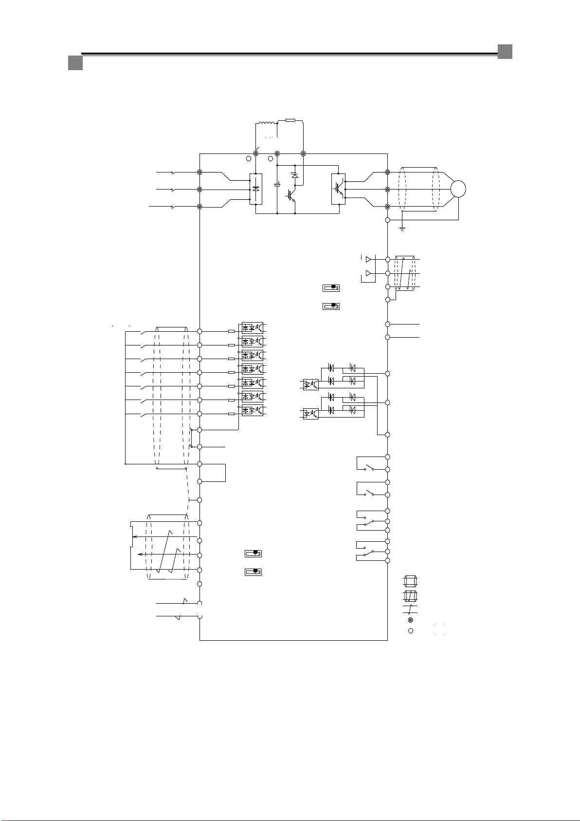
Inverter terminals wiring diagram
Applicable to models (≤30kW) that do not have a built-in DC reactor but have a built-in brake unit.
200V级220VAC
50/60Hz
X0
X1
X2
X3
X4
X5
X6
XV
24(+24V)
XC
XC
V+
A0
A1
V-
PE
Modbus通讯接口
4C
4B
4A
3C
3B
3A
YC
Y1
Y0
0V
M1
M0
A+
B-
可编程多功能输入信号
模拟量输入0
(-10V~+10V或
0~20mA可选)
模拟量输入1
(-10V~+10V或
0~20mA可选)
可编程继电器输出3
可编程继电器输出4
可编程集电极开路输出1
多功能模拟量输出1
多功能模拟量输出0
可编程集电极开路输出0
三相电源
400V级380~460VAC R/L1
S/L2
T/L3
U/T1
V/T2
W/T3 M
0V
屏蔽线
屏蔽双绞线
双绞线
PE
主回路接线端子
控制回路接线端子
+1 B
+2
短路块
制动电阻
可外接直
流电抗器
AS180高性能VF通用变频器
UI
A0/SW4
UI
A1/SW3
拨动开关
P1
P2 PTC保护点
1A
1B
2A
2B 可编程继电器输出2
可编程继电器输出1
UI
M0/SW6
U
M1/SW5
I
拨动开关
Figure 2.4 Schematic diagram for terminals wiring of AS180 inverter (30kW and below)
Note: The input power supply in the figure is given as an example of three-phase power input, and the 400V
level of input phase is 380~460V.
Three-phase power supply
400V level 380~460VAC
200V level 200VAC
Programmable
multi-function input
signal
Analog input 0
(-10V~+10V or
0~20mA optional)
Analog input 1
(-10V~+10V or
0~20mA optional)
Slide switch
Slide switch
AS180 High Performance V/F
General Purpose Inverter
Braking
resistor
External
DC reactor
Short
circuit
block
Multi-function
analog output 0
Multi-function
analog output 1
PTC protection point
Programmable Open
Collector Output 0
Programmable Open
Collector Output 1
Programmable relay
output 1
Programmable relay
output 2
Programmable relay
output 3
Programmable relay
output 4
Shielded wire
STP
Twisted pair
Main circuit
terminal
Control circuit
terminal
Communication interface

AS180 Series High Performance V/F General Purpose Inverter Operation Manual
- 7 -
Applicable to models (>30kW) that have a built-in DC reactor but do not have a built-in brake unit.
200V级220VAC
50/60Hz
X0
X1
X2
X3
X4
X5
X6
XV
24(+24V)
XC
XC
V+
A0
A1
V-
PE
Modbus通讯接口
4C
4B
4A
3C
3B
3A
YC
Y1
Y0
0V
M1
M0
A+
B-
可编程多功能输入信号
模拟量输入0
(-10V~+10V或
0~20mA可选)
模拟量输入1
(-10V~+10V或
0~20mA可选)
可编程继电器输出3
可编程继电器输出4
可编程集电极开路输出1
多功能模拟量输出1
多功能模拟量输出0
可编程集电极开路输出0
三相电源
400V级380~460VAC R/L1
S/L2
T/L3
U/T1
V/T2
W/T3 M
0V
屏蔽线
屏蔽双绞线
双绞线
PE
主回路接线端子
控制回路接线端子
AS450通用矢量型变频器
UI
A0/SW4
UI
A1/SW3
拨动开关
P1
P2 PTC保护点
1A
1B
2A
2B 可编程继电器输出2
可编程继电器输出1
UI
M0/SW6
UI
M1/SW5
拨动开关
-
+
内置直
流电抗器
Figure 2.5 Schematic diagram for terminals wiring of AS180 inverter (30kW and above)
Note: Analog voltage and current optional signals can be input through A0/A1. Input simultaneously
through A0 and A1 can be input at the same time.
The inverter of this specification does not have a brake unit and provides terminals for an external
brake unit.
AS180 High Performance V/F
General Purpose Inverter
Built-in DC
reactor
Three-phase power supply
400V level 380~460VAC
200V level 200VAC
Programmable multi-function
input signal
Analog input 0
(-10V~+10V or
0~20mA optional)
Analog input 1
(-10V~+10V or
0~20mA optional)
Communication interface
Slide switch
Slide switch
Multi-function
analog output 0
Multi-function
analog output 1
PTC protection point
Programmable Open
Collector Output 0
Programmable Open
Collector Output 1
Programmable relay
output 4
Programmable relay
output 3
Programmable relay
output 2
Programmable relay
output 1
Shielded wire
STP
Twisted pair
Main circuit
terminal
Control circuit
terminal
Shanghai Sigriner STEP Electric Co., Ltd.
- 8 -
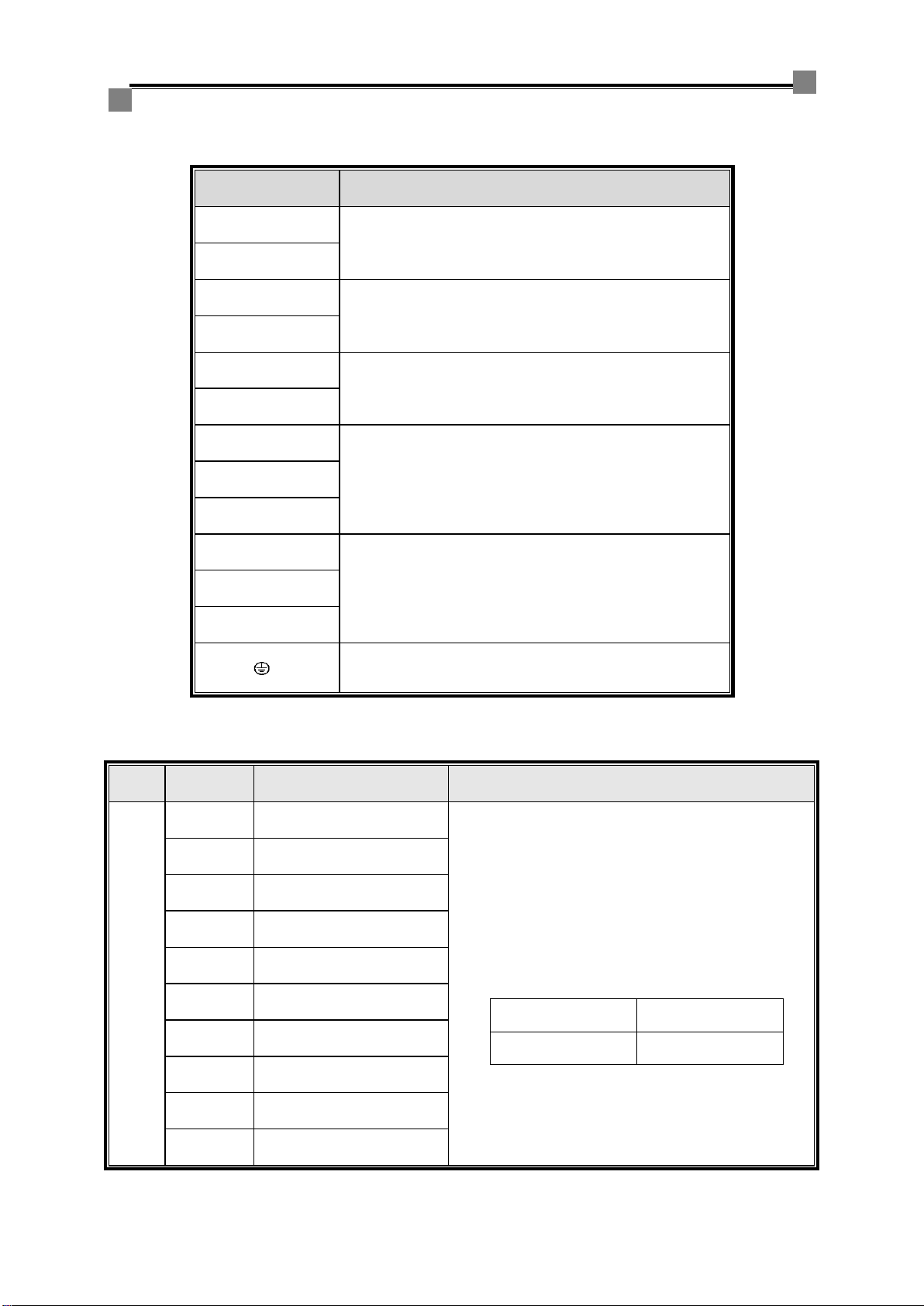
Main circuit terminals description
Table 2.2 Description of functions of the main circuit terminals
Terminal marks
Functions description
○+1
An external DC reactor can be connected, which has been
short connected in the factory
○+2
○+2
External braking resistor connection
B
○+2/○+
DC bus positive and negative output terminals, allowing for
connection of external brake unit or common DC bus
○-
R/L1
Main circuit AC power input, connected to a three-phase
input power supply
S/L2
T/L3
U/T1
Inverter output, connected to a three-phase asynchronous
motor
V/T2
W/T3
Grounding terminal, connected to the protective ground, the
grounding resistance at 400V level cannot be greater than
4Ω
Control circuit terminals description
Table 2.3 Control circuit terminals description
Nam
e
Terminal
marks
Signal name
Remarks
D i g i t a l i n p u t t e r m i n a l
X0
Multi-function input 0
(function code P30.00)
Contact input, the input signal is valid when the
contact is closed. The function can be selected
according to the parameters of the function group (code
P30 ).
Digital input circuit specifications are as follows:
Internal power
supply
+24VDC
Maximum load
current
100mA
X1
Multi-function input 1
(function code P30.01)
X2
Multi-function input 2
(function code P30.02)
X3
Multi-function input 3
(function code P30.03)
X4
Multi-function input 4
(function code P30.04)
X5
Multi-function input 5
(function code P30.05)
X6
Multi-function input 6
(function code P30.06)
24
Internal +24VDC power
output
XV
Input signal common port
XC
Internal 24V power supply 0V

AS180 Series High Performance V/F General Purpose Inverter Operation Manual
- 9 -
Nam
e
Terminal
marks
Signal name
Remarks
Analo
g
input
termi
nal
A0
Multi-function analog input 0
(function code P32.01)
Voltage or current analog input, selected by toggling
switch (SW4, SW3):
Analog voltage input: -10V to +10V or 0 to 10V, Rin>34kΩ
Analog current input: 0~20mA or 4~20mA, Rin=120Ω
Can be used for analog signal input at a
given speed
A1
Multi-function analog input 1
(function code P32.07
(voltage)
V+
+10V power output
+10VDC power supply output for analog input,
maximum allowable current 20mA
V-
-10V power output
-10VDC power supply output for analog input, maximum
allowable current 20mA
0V
Analog input signal reference
ground
Analog input signal reference ground
R e la y o u t p u t te r min a l
1A
1B
Programmable relay output
(Function code P31.00)
Normally open contact
The programmable relay output function can be
selected according to the parameters of the function
code P31 group.
Contact specifications are as follows:
Project
Description
Rated capacity
5A/250VAC
5A/30VDC
Open/close
frequency 120
times / min
Failure rate P level
10mA/5V
Actuation time
below 10ms
2A
2B
Programmable relay output
(Function code P31.01)
Normally open contact
3A
3B
3C
Programmable relay output3
(Function code P31.02)
3A-3B:Normally open
contact
3B-3C:Normally closed
contact
The programmable relay output function can be
selected according to the parameters of the function
code P31 group.
Contact specifications are as follows:
Project
Description
Rated
capacity
Resistive, 4.5A 250VAC/30VDC
Sensitive, 0.4A 250VAC/30VDC
Open/close
frequency
120 times /
min
Failure rate P level
10mA/5V
Actuation
time
below 10ms
4A
4B
4C
Programmable relay output 4
(Function code P31.03)
4A-4B:Normally open
contact
4B-4C:Normally closed
contact
Trans
istor
set
open
outpu
t
termi
nal
Y0
Programmable set open
output 0
(Function code P31.04)
The programmable set open output function can be
selected according to the parameters of the function
code P31 group.
Drive capacity: no more than DC30V, 20mA
Y1
Programmable set open
output 1
(Function code P31.05)
YC
Programmable set open
output common port
Analo
g
outpu
t
termi
nal
M0
Programmable analog output
0
(Function code P33.00)
Voltage or current analog output, selected by toggling
switch (SW6, SW5):
Analog voltage output: -10V to +10V or 0 to 10V, RL≥1kΩ
Analog current output: 0 to 20 mA or 4 to 20 mA, RL ≤ 500
Ω
Can be used for monitor output
M1
Programmable analog output
1
(Function code P33.03)
0V
Analog output signal
reference ground
Analog output signal reference ground
Over
Temp
erature
Protec
tion
P1,P2
PTC function connection port
(Function code P30.07)
Matched temperature sensor model: PT1000
Over temperature protection point: 120 °C
State
indicator
(green) D35
ON: The temperature is normal
OFF: Over temperature protection

Shanghai Sigriner STEP Electric Co., Ltd.
- 10 -
Nam
e
Terminal
marks
Signal name
Remarks
Modbu
s
Com
muni
catio
n
Termin
al
A+
Modbus communication
signal +
Signal terminal for Modbus communication
Commun
ication
status
indicator
Yello
w
(TX)
D36
ON: The IO board is in the
state of sending data to the
bus
OFF: The IO board is in the
state of not sending data
Gre
en
(TX)
D37
ON: The IO board is in the
state of receiving data from
the bus
OFF: The IO board is in the
state of not receiving data
B-
Modbus communication
signal -
+5
Signal power supply +5
Communication signal isolated power supply 5V, 100mA
SC
Signal ground
MODBUS communication signal
ground
Grou
nd
termi
nal
AE
RC ground terminal
Grounding through the RC circuit, the shield can be
grounded through the RC circuit when the communication
cable is too long and the interference is large.
PE
Direct ground terminal
Direct grounding, suitable for situations with good
grounding conditions, analog, communication line shield
layer grounding
Note: The analog signal cable is a twisted pair shielded cable, and the shield layer is properly grounded.
And the distance to the power line is more than 5cm, preferably carry out cross-wiring with the power line,
trying not to keep it parallel to the power line, the shield layer can be connected to the inverter housing.

AS180 Series High Performance V/F General Purpose Inverter Operation Manual
- 11 -
Chapter 3 Inverter Quick Commissioning
1. Inverter commissioning steps before power up
(1) Main circuit terminal wiring and confirmation:
1. The three-phase power input lines are connected to the inverter terminals R/L1, S/L2, and T/L3,
respectively.
2. The three-phase output terminals U/T1, V/T2 and W/T3 of the inverter are respectively connected
to the three-phase stator side windings of the motor.
3. The 30kW and below inverters come with a brake unit. The braking resistor is installed between
the B and ○+2 terminals. For >30kW inverters, to brake circuit, please connect an external brake
unit between the ○+and ○-terminals.
4. For 30 kW and below inverters, if DC reactors are required, please install them between the ○+1
and ○+2 terminals, while removing the short-connected piece between ○+1 and ○+2 terminals.
5. Then confirm if the above connections are secure.
U/T1
V/T2
W/T3
+1 +2
R/L1
S/L2
T/L3
-
B
+-
Figure 3.1 Main circuit terminal wiring diagram
(2). IO board control terminal wiring and confirmation:
1. When the external controller input switching value quantity signal is a dry node, confirm that
terminals 24 and XV are shorted.
Example: Multi-speed control terminal wiring
There are 16 kinds of multi-speed frequency available for selection. The external needs 4 switching
value input terminals for combination. For example, select X3, X4, X5 and X6 terminals. The specific
wiring is that four wires are externally controlled to be connected to X3, X4, X5 and X6, respectively,
and the other corresponding four wires connected to the XC terminal.
2. Switching value relay output terminal, 1A and 1B are normally open points, 1B and 1C are normally
closed points, and so on for other relays.
3. External voltage or current signal is optional for analog input, the external reference signal line is
connected to the OV terminal, and the signal line connected to A0 or A1 terminal (A1 is optional in
current type input);
use the
shielded wire
AS180
inverter IO
board
A0/A1
0V
PE
Analog
input
Upper
controller
Speed reference
0V
Figure 3.2 Analog input terminal wiring diagram
When the potentiometer is selected as the analog input, both terminals of the potentiometer are
connected to V+, and V- (or OV), and the potentiometer terminals are connected to A0 or A1.

Shanghai Sigriner STEP Electric Co., Ltd.
- 12 -
use the
shielded wire AS180 inverter IO
board
V+
A0/A1
V-/OV
PE
Analog voltage
input(-
10V~+10V)
potentio
meter
Figure 3.3 Analog (potentiometer) input terminal wiring diagram
4. Analog output terminal wiring:
use the
shielded wire Upper
controller
0V
PE
Analog
output
AS180 inverter
IO board
M0/M1
0V
V+
Figure 3.4 Analog output terminal wiring diagram
2. Inverter commissioning steps after power up
1. Confirm the rated power P96.00, the rated current P96.01, and the rated voltage P96.03 of the
inverter are the same as the actual parameters on the nameplate.
2. At first on-site commissioning, first perform factory reset. Parameter processing Init = 7 Select Y
to perform factory reset.
3. Monitor status to see if Udc is around 540V.
4. Confirm whether the controlled motor is an asynchronous motor. Parameters on the motor
nameplate include: rated power, rated voltage, rated current, rated frequency, rated speed,
number of motor poles and slip. Write these data into the corresponding parameters of the P20
group.
Slip calculation fs=(synchronous speed - rated speed)*number of motor pole pairs/60
For example, motor nameplate parameters: rated frequency 50Hz, 4 poles, rated speed 1470rpm,
the slip frequency is fs=(1500-1470)*2/60=1Hz.
3. Parameter settings:
1. List of commonly used parameters in commissioning:
Parameter no.
Name
Set value (remarks)
P10.00
Control mode selection
0: VF control 5: High performance VF control
P10.02
Command channel selection
Normal selection: 1
P10.03
Speed channel selection
Normal selection: 1 or 3 or 5 or 15
P11.00
Start mode selection
Default
P12.00
Stop mode selection
0: by inertia 1: slow down
P20.01
Motor 1 rated power
A parameter on motor nameplate
P20.02
Motor 1 rated current
A parameter on motor nameplate

AS180 Series High Performance V/F General Purpose Inverter Operation Manual
- 13 -
Parameter no.
Name
Set value (remarks)
P20.03
Motor 1 rated frequency
A parameter on motor nameplate
P20.04
Motor 1 rated speed
A parameter on motor nameplate
P20.05
Motor 1 rated voltage
A parameter on motor nameplate
P20.06
Motor 1 pole number
A parameter on motor nameplate
P20.07
Motor 1 rated slip
Calculated according to parameters on motor
nameplate
P30.00
Input Di0 function
Default
P30.01
Input Di1 function
Default
P31.00
K1 function
Normal selection: 2 or 3
P31.01
K2 function
Normal selection: 3 or 2
P40.02
Acceleration time
Site request setting
P40.03
Deceleration time
Site request setting
2. If you select P10.03=1 digital for multi-speed setting, you need to set the parameters, such as
select X3, X4, X5, X6, terminal as multi-speed set signal
Parameter no.
Name
Set value
P30.03
Input Di3 function
3
P30.04
Input Di4 function
4
P30.05
Input Di5 function
5
P30.06
Input Di6 function
6
3. If you select P10.03=3 or 5 analog A0/A1 for target speed setting, you need to set the parameters.
Parameter no.
Name
Set value
P32.00
Input AI0 type
0:0~10V 1:-10~+10V 2:0~20mA 3:4~20mA
P32.02
Input AI0 lower limit
General default
P32.03
Input AI0 upper limit
General default
P32.06
Input AI1 type
0:0~10V 1:-10~+10V 2:0~20mA 3: 4~20mA
P32.08
Input AI1 lower limit
General default
P32.09
Input AI1 upper limit
General default
P32.11
Input AI1 limit range
General default value; when P32.06=2 or 3, this
value is set to 20.000mA
Note: When the analog input voltage value displayed on the operator is not equal to the input voltage value,
the A0 or A1 lower limits can be adjusted and upper limits increased, so that the actual voltage value is
equal to the displayed value.

Shanghai Sigriner STEP Electric Co., Ltd.
- 14 -
4. If you select P10.03=15 UP/DOWN for speed setting, you need to set the parameters, such as
selecting input terminal X1 as the UP signal and terminal X3 as the DOWN signal.
Parameter no.
Name
Set value
P30.01
Input Di1 function
31 or 38
P30.03
Input Di3 function
32 or 39
4. Special functions description
1. Selection of function below the lower limit frequency
Parameter no.
Name
Set value
P70.01
Lower frequency limit
Site request setting
P70.22
Selection below lower limit
frequency
0: Run according to the limit frequency 1: Stop
2: Set frequency is 0
Note: In some cases, the running command is always maintained. When the motor speed is lower than
a certain frequency, the inverter output voltage is zero. At this time, set P70.01=0.50Hz (if it is lower than
0.5Hz), P70.22 =1; that is, when the output frequency is lower than 0.5Hz, the inverter stops, and when
output frequency is above 0.5Hz, the inverter is started.
2. Analog input description
When the analog input function is selected as for target speed setting, 10V corresponds to the set speed
reference value P20.13 (maximum frequency of motor 1). For example, when P20.13=50.00Hz, if you
input 10V, set speed is 50Hz, if you input 5V, set speed is 25 Hz, and so on.
3. Analog output description
Analog output is 0~5V, corresponding to 0~100% rated value (such as rated speed, rated current, etc.), if
you want 0~100% rated value (such as rated speed, rated current, etc.), and the corresponding output is
0~10V, you can set the output P33.02 or P33.05.
4. Speed tracking start
To select this function, you need to set P11.00=2, and set the P11.14 parameter value.
Parameter no.
Name
Set value
P11.00
Start mode selection
2
P11.14
Maximum current during
tracking
Setting range 30~100%; set according to loading
conditions
5. Inverter test run process
1. Motor no-load test run
Check if the motor is in no-load state (disconnect from the machine)
For the first test run, the set frequency should not be too large, 5Hz is enough .
Check if the motor running direction is consistent with the set one?
Check if the motor acceleration and deceleration are smooth, with no abnormal sound
During test running, the actual current Irms is approximately 30% of the rated current of
motor
The output voltage value Uout is substantially linear with the current frequency value Vref
2. Motor loaded test run
Check if the motor is connected to mechanical equipment and confirm the safety of motor
and mechanical equipment
When loaded running starts, be ready to press the STOP button (if there is an abnormality)
Check if the load running direction is consistent with the set direction on the inverter?
Check if the motor acceleration and deceleration are smooth during running with load
Check if the actual motor current Irms is too large
Check if there is an abnormal sound or current oscillation when load frequency changes.

AS180 Series High Performance V/F General Purpose Inverter Operation Manual
- 15 -
6. Precautions
1. VF control refers to P10.00 = 0 control mode. If current oscillation occurs, try to adjust P61.06
and P61.07 parameters. See the table below for details.
Parameter no.
Name
Set value
P61.06
U/F control current loop
Max
Generally set to the default value; When P10.00=0
is active, current oscillation occurs, adjust this value
(change 0.2% for each time)
P61.07
U/F control current loop
Min
Generally set to default value; When P10.00=0 is
active, current oscillation occurs, adjust this value
(change 0.2% for each time)
2. High-performance VF control refers to P10.00 = 5 control mode. If the motor with heavy load
fails to start due to over-current, you can try to adjust the following parameters. See the table
below for details.
Parameter no.
Name
Set value
P71.35
SVC1 inertia coefficient
Generally set to default value; When P10.00=5 is
active, motor starts with heavy load, this value can
be increased; do not exceed 200% when setting
P71.36
SVC1 low speed torque
boosting
Generally set to default value; When P10.00=5 is
active, motor starts with heavy load, this value can
be increased; generally set to 150%~200%
3. If it is found that the motor noise is large at running, appropriately increase the PWM carrier
frequency value (P71.14 parameter) under the condition that the inverter does not report fault.

Other STEP Inverter manuals

Popular Inverter manuals by other brands

BlueHive
BlueHive 011-1945-0 instruction manual

SOLIS
SOLIS RHI-5G Series instruction manual

Mitsubishi Electric
Mitsubishi Electric 800 Series instruction manual

Toshiba
Toshiba PCT001Z-E instruction manual

Ryobi
Ryobi RG-1250I Owner's operating manual

Siemens
Siemens SINUMERIK 880 Installation operation & maintenance


Perfect power systems
Perfect power systems EXT Series Installation and operation manual

GivEnergy
GivEnergy Giv-AC3.0 user manual

Alpha Technologies
Alpha Technologies INVERTER 2000 user manual

Srne
Srne HF2420S40-75 user manual

SEW-Eurodrive
SEW-Eurodrive MOVIDRIVE system Compact operating instructions

Ego Paris
Ego Paris EM16 Assembly instructions