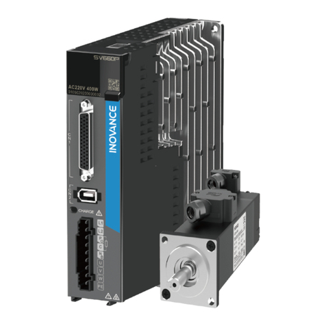
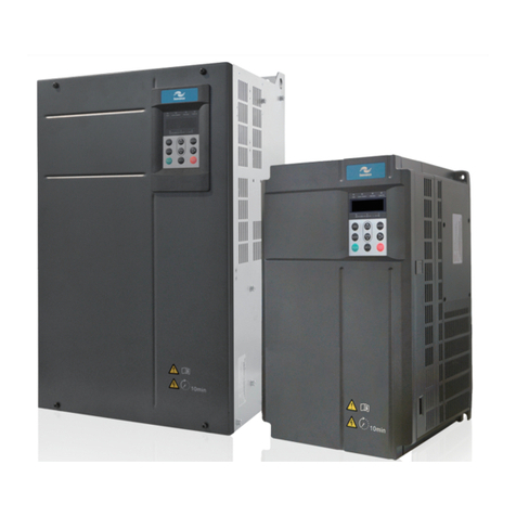
Emheater EM12-Z Series User manual

User ManualEM12-Z Series Servo Drive
EMHEATER
China EM Technology LimitedChina EM Technology LimitedAddress:No.80, Baomin 2 road, Xixiang, Bao'an District,Shenzhen ,ChinaPhone:86-0755-29985851Fax:86-0755-29970305Zip code:518101Website :Http://www.emheater.com
EMHEATER
R

EM12-Z series user manual
1
1. Safety Information and Precautions
In this manual, the notices are graded based on the degree of danger:
Danger
Indicates that failure to comply with the notice will result in severe personal injury or
even death.
Warning
Indicates that failure to comply with the notice will result in personal injury or
property damage.
Read this manual carefully so that you have a thorough understanding. Installation, commissioning or
maintenance may be performed in conjunction with this chapter. EMHEATER will assume no liability or
responsibility for any injury or loss caused by improper operation.
1.1 Safety Information
Before
installation Danger
Do not use damaged or missing components frequency inverter. Failure to
comply will result in personal injury.
Please use the electric motor with upper B insulation class. Failure to comply
will result in personal injury.
During
installation
Danger
Install the frequency inverter on incombustible objects such as metal, and keep it
away from combustible materials. Failure to comply may result in a fire.
Warning
When two frequency inverters are laid in the same
cabinet, arrange the
installation positions properly to ensure the enough cooling effect.
Do not drop wire residue or screw into the frequency inverter. Failure to comply
will result in damage to the frequency inverter.
Wiring
Danger
Wiring must be performed only by qualified personnel under instructions
described in this manual. Failure to comply may result in unexpected accidents.
A circuit breaker must be used to isolate the power supply and the frequency
inverter. Failure to comply may result in a fire.
Ensure that the power supply is cut off before wiring. Failure to comply may
result in electric shock.
Connect the frequency inverter to ground properly by standard. Failure to
comply may result in electric shock.
Warning
Never connect the power supply cables to the output terminals (U, V, W) of the
Frequency inverter. Failure to comply will result in damage to the frequency
inverter.
Make sure that all the connecting wires comply with the requirement of EMC
and the saf
ety standard in the region. Use wire sizes recommended in the
manual. Failure to comply may result in accidents.
Never connect the braking resistor between the DC bus terminals (P+) and (P-).
Failure to comply may result in a fire.
Before
power-on
Check that the following requirements comply with:
The voltage class of the power supply is consistent with the rated voltage class of

EM12-Z series user manual
2
Danger
the frequency inverter. The input terminals (R, S, T) and output terminals (U, V,
W) are properly connected. No short-
circuit exists in the peripheral circuit. The
wiring is fastened. Failure to comply will result in damage to frequency inverter.
Cover the frequency inverter properly before power-on to prevent electric shock.
Before
power-on
Warning
Do not perform the voltage resistance test on any part of the frequency inverter
because such test has been done in the factory. Failure to comply will result in
accidents.
All peripheral devices must be connected properly under the instructions
described in this manual. Failure to comply will result in accidents.
After
power-on
Danger
Do not open the frequency inverter’s cover after power-
on to prevent from
electric shock.
Do not touch the frequency i
nverter with wet hand and its peripheral circuit to
prevent from electric shock.
Do not touch the terminals of the frequency inverter (including the control
terminals). Failure to comply may result in electric shock.
Do not touch the U, V, W terminal or mo
tor connecting terminals when
frequency inverter automatically does safety testing for the external high-voltage
electrical circuit. Failure to comply may result in electric shock.
Warning
Note the danger during the rotary running of motor when check
the parameters.
Failure to comply will result in accidents.
Do not change the factory default settings of the frequency inverter. Failure to
comply will result in damage to the frequency inverter.
During
operation
Danger
Do
not go close to the equipment when selected the restart function. Failure to
comply may result in personal injury.
Do not touch the fan or the discharging resistor to check the temperature. Failure
to comply will result in personal injury.
Signal detection must be performed only by qualified personal during operation
Warning
Avoid objects falling into the frequency inverter when it is running. Failure to
comply will result in damage to frequency inverter.
Do not start/stop the frequency inverter by tur
ning the contactor ON/OFF.
Failure to comply will result in damage to the frequency inverter.
Maintenance
Danger
Do not repair or maintain the frequency inverter at power-
on. Failure to comply
will result in electric shock.
Repair or maintain the frequency inverter only after the charge light on
frequency inverter is powered off. This allows for the residual voltage in the
capacitor to discharge to a safe value. Failure to comply will result in personal
injury.
Repair or mai
ntenance of the frequency inverter may be performed only by
qualified personnel. Failure to comply will result in personal injury or damage to
the frequency inverter.

EM12-Z series user manual
3
2. Product Information
2.1 Designation Rules
Diagram 2-1 Designation rules
2.2 Model parameter comparison table
Model
Power
Capability
(KVA)
Input
Current
(A)
Output
Current
(A)
Adaptable Motor Thermal Power
Consumption
(KW)
(KW) (HP)
Single-phase:220V,50/60Hz
EM12-Z1-d75 1.5 8.2 4 0.75 1 0.030
EM12-Z1-1d5 3 14 7 1.5 2 0.055
EM12-Z1-2d2 4 23 9.6 2.2 3 0.072
Three-phase:220V,50/60Hz
EM12-Z2-d75 3 5 3.8 0.75 1 0.030
EM12-Z2-1d5 4 5.8 5.1 1.5 2 0.055
EM12-Z2-2d2 5.9 10.5 9 2.2 3 0.072
EM12-Z2-004 8.9 14.6 13 3.7 5 0.132
EM12-Z2-5d5 17 26 25 5.5 7.5 0.214
EM12-Z2-7d5 21 35 32 7.5 10 0.288
EM12-Z2-011 30 46.5 45 11 15 0.489
EM12-Z2-015 40 62 60 15 20 0.608
EM12-Z2-018 57 76 75 18.5 25 0.716
EM12-Z2-022 69 92 91 22 30 0.887
EM12-Z2-030 85 113 112 30 40 1.11
EM12-Z2-037 114 157 150 37 50 1.32
EM12-Z2-045 134 180 176 45 60 1.66
EM12-Z2-055 160 214 210 55 75 1.98
EM12-Z2-075 231 307 304 75 100 2.02
Three-phase:380V,50/60Hz
EM12-Z3-d75
3
5
2.1 0.75 1 0.050
EM12-Z3-1d5
4
5.8
3.8 1.5 2 0.066
EM12-Z3-2d2
5.9
10.5
5.1 2.2 3 0.120
EM12-Z3-004
8.9
14.6
9 3.7 5 0.195
EM12-Z3-5d5 11 20.5 13 5.5 7.5 0.262
EM12-Z3-7d5
17
26
17
7.5
10
0.445

EM12-Z series user manual
4
Model
Power
Capability
(KVA)
Input
Current
(A)
Output
Current
(A)
Adaptable Motor
Thermal Power
Consumption
(KW)
(KW) (HP)
EM12-Z3-011
21
35
25
11
15
0.553
EM12-Z3-015 24 38.5/ 32 15 20 0.651
EM12-Z3-018
30
46.5
37
18.5
25
0.807
EM12-Z3-022 40 62 45 22 30 1.01
EM12-Z3-030
57
76
60
30
40
1.20
EM12-Z3-037 69 92 75 37 50 1.51
EM12-Z3-045
85
113
91
45
60
1.80
EM12-Z3-055 114 157 112 55 75 1.84
EM12-Z3-075
134
180
150
75
100
2.08
EM12-Z3-090 160 214 176 90 125 2.55
EM12-Z3-110
192
256
210
110
150
3.06
EM12-Z3-132 231 307 253 132 200 3.61
EM12-Z3-160
250
385
304
160
250
4.42
EM12-Z3-200 280 430 377 200 280 4.87
EM12-Z3-220
355
468
426
220
300
5.51
EM12-Z3-250 396 525 465 250 370 6.21
EM12-Z3-280 445 590 520 280 400 7.03
EM12-Z3-315 500 665 585 315 420 7.81
EM12-Z3-355
565
785
650
355
500
8.51
EM12-Z3-400 630 883 725 400 530 9.23
EM12-Z3-450
650
920
820
450
600
9.52
2.3Product appearance and installation dimension
2.3.1 Product appearance
Diagram 2-3 Product appearance (With potentiometer)

EM12-Z series user manual
5
Diagram 2-4 Appearance and installation dimension (Plastic housing structure)

EM12-Z series user manual
6
2.3.2 Appearance and Installation Hole Dimension (mm)
Model
Appearance and installation dimension(mm)
W
W1
H
H1
D
D1
Φd
Single-phase 220V
EM12-Z1-d75
118 106.5 185 175.5 157 -- Φ4.5
EM12-Z1-1d5
EM12-Z1-2d2
Three-phase 220V
EM12-Z2-d75
118 106.5 185 175.5 157 -- Φ4.5
EM12-Z2-1d5
EM12-Z2-2d2
EM12-Z2-004 160 148 247 235 177 -- Φ5.5
EM12-Z2-5d5
EM12-Z2-7d5 220 205 320 305 198 -- Φ5.5
EM12-Z2-011
EM12-Z2-015 300 220 540 500 240 -- Φ7
EM12-Z2-018
EM12-Z2-022 340 260 580 540 270 -- Φ10
EM12-Z2-030
EM12-Z2-037 410 260 610 575 280 -- Φ12
EM12-Z2-045
EM12-Z2-055 460 320 710 690 335 -- Φ12
EM12-Z2-075
535
360
885
830
370
--
Φ12
Three-phase 380V
EM12-Z3-d75
118 106.5 185 175.5 157 -- Φ4.5
EM12-Z3-1d5
EM12-Z3-2d2
EM12-Z3-004
EM12-Z3-5d5
EM12-Z3-7d5 160 148 247 235 177 -- Φ5.5
EM12-Z3-011
EM12-Z3-015
220 205 320 305 198 -- Φ5.5
EM12-Z3-018
EM12-Z3-022
EM12-Z3-030 300 220 540 500 240 -- Φ7
EM12-Z3-037
EM12-Z3-045 340 260 580 540 270 -- Φ10
EM12-Z3-055
EM12-Z3-075 410 260 610 575 280 -- Φ12
EM12-Z3-090
EM12-Z3-110 460 320 710 690 335 -- Φ12
EM12-Z3-132
EM12-Z3-160 535 360 885 830 370 -- Φ12

EM12-Z series user manual
7
Model
Appearance and installation dimension(mm)
W W1 H H1 D D1 Φd
EM12-Z3-185
EM12-Z3-200
EM12-Z3-220
EM12-Z3-250
650 360 1040 985 415 -- Φ12
EM12-Z3-280
EM12-Z3-315
EM12-Z3-355
815 600 1350 1250 445 -- Φ12
EM12-Z3-400
EM12-Z3-450
2.3.3 Appearance and installation dimension of external keypad (keypad tray)
Diagram 2-7 Appearance and installation dimension of external keypad (keypad tray)

EM12-Z series user manual
8
3.Installation of Frequency Inverter
3.1 Installation environment
1. The place with indoor vents or ventilation devices.
2. The environment temperature shall be -10℃~40℃. If the temperature is over 40℃but less than 50℃, better to
take down the cover of frequency inverter or open the front door of cabinet to facilitate heat dissipation.
3. Try to avoid high temperature and wet place; the humidity shall be less than 90% without frost deposit.
4. Avoid direct sunlight.
5. Keep away from flammable, explosive and corrosive gas and liquid.
6. No dust, floating fiber and metal particles.
7. Install on the place without strongly vibration. And the vibration should be not over 0.6G, Especially pay
attention to far away from the punching machine, etc.
8. Keep away from electromagnetic interference source.
3.2 Installation direction and space
In order to not affect the service life of frequency inverter and reduce its performance, note for its installation
direction and space and correctly fasten it.
Diagram3-1 Ventilating duct installation dimension diagram of frequency inverter
Please install the frequency inverter vertically, to send out the heat upward, and pay attention to direction of
frequency inverter to avoid inversion.
If there are several units of frequency inverter installed, please install them side by side, do not to install up and
down.
3.3 Sketch and Description of Main Circuit Terminals
Terminal symbol Function description
L/R、N/T Single-phase AC power input terminals
R/L1、S/L2、T/L3 Three-phase AC power input terminals
P+、PB Braking resistor connecting
○
+1、
External DC reactor connecting terminals,shorted by bronze before
delivery
○+2
P+、P-/○
-DC power input terminals

EM12-Z series user manual
9
Terminal symbol Function description
Or E/PE Grounding terminal
U/T1、V/T2、W/T3 Three-phase AC power output terminals
3.4 Control Circuit and Main Circuit Terminals Description
3.4.1 Control Circuit and Main Circuit Wiring
Diagram 3-2 Control Circuit and Main Circuit Wiring
Diagram 3-3 EM12 Control Circuit Terminal Sketch

EM12-Z series user manual
10
Terminal
Symbol
Terminal Name Terminals function description
+24V-COM External +24V
power supply
Provide +24 V power supply to external unit. Generally, it provides
power supply to DI/DO terminals and external sensors.Maximum
output current: 200 mA
AI1-GND
Analog input 1
1. Input range: DC 0V~10V/ 0mA~20mA(decided by jumper AI2/AI3
on the control board); AI1: DC -10V~+10V
2. Impedance: 22 kΩ (voltage input), 500 Ω (current input)
AI2-GND
Analog input 2
AI3-GND Analog input 3
DI1
Digital input 1
1. Optical coupling isolation, compatible with dual polarity input
2.Input Impedance: 2.4 kΩ
3. Voltage range for level input: 9V~30 V
DI2
Digital input 2
DI3
Digital input 3
DI4
Digital input 4
DI5
Digital input 5
AO1-GND Analog output 1
Voltage or current output is decided by jumper AO1.
Output voltage range: 0V~10 V
Output current range: 0mA~20 mA
T1/A-T1/B
T2/A-T2/B
NC terminal Contact driving capacity: 250 VAC, 3 A, COSø = 0.4
DC 30 V, 1 A
T1/A-T1/C
T2/A-T2/C
NO terminal
3.5Encoder board terminal wiring and definition

EM12-Z series user manual
11
4. Operation and display
4.1Instruction of operation and display
With the operation panel, the inverter can be used to modify the function parameters, the inverter working status
monitoring and the inverter running control (starting, stopping). The appearance and function are as follows:
Diagram 4-1Operatin panel
1. Description of indicator:
RUN: OFF indicates that the frequency inverter is in the stop state and ON indicates that the frequency inverter is
in the running state.
LOCAL: It indicates whether the frequency inverter is operated by operation keypad, terminals or remoter
(communication). OFF indicates keypad operation control state; ON indicates terminals operation control state;
Blinking indicates remote operation control state.
DIR: It is Forward/Reversal indicator, ON indicates forward rotation.
TRIP: Tunning/ Torque Control/Fault indicator
When the indicator is ON, it indicates torque control mode. When the indicator is blinking slowly, it indicates the
auto-tuning state. When the indicator is blinking quickly, it indicates the fault state.
2. Unit indicator:
Hz: frequency unit; A: Current unit; V: Voltage unit
3. Digital display area:
The 5-digit LED display is able to display the set frequency, output frequency, monitoring data and fault codes.
4. Description of Keys on the Operation panel (keypad)
Key
Name
Function
PRG/ESC Programming Enter or exit menu level I.
ENTER
DATA Confirmation Enter the menu interfaces level by level, and confirm the parameter
setting
▲
Increment
Increase data or function code.
▼
Decrement
Decrease data or function code.
Shift
Select the displayed parameters in turn in the stop or running state, and
select the digit to be modified when modifying parameters.
RUN
RUN
Start the frequency inverter in the operation panel control mode.

4. Operation and display EM12 series user manual
12
Key Name Function
RESET
STOP Stop/Reset
Stop the frequency inverter when it is in the running state and perform
the reset operation when it is in the fault state. The functions of this key
are restricted by b9-00.
MF·K
Multi-function Perform function switchover according to the setting of P9-01

EM12-Zseries user manual
13
Chapter 5. Simple parameter list
Table Symbol Description:
“√” - indicates that the parameter can be changed in the process of stopping and running.
“╳” - indicates that the parameter can be changed in stop mode, can not be changed during running;
“●” - Indicates that the initial parameters related to the drives model
“*” Factory setting, it is not allow setting by user.
Code
Name
Setting range
Default
Property
P0 Basic function parameters
P0-00 GP model display 1: G type(Heavy duty)
2: P type(pumps, fans load duty)Per model ●
P0-01 The first motor control mode
0:VF control
1:Sensorless vector control without PG card
feedback
2: Sensor vector control with PG card
feedback
0 ╳
P0-02 Command mode
0: Keypad ( LED OFF)
1:Terminal command ( LED ON)
2: RS485 communication (LED flash)
0 √
P0-03 Main frequency reference
source X
0: Set by P0-08 of keypad, UP/DOWN
setting not saved after power down.
1: Set by P0-08 of keypad, UP/DOWN
setting memorized power down.
2: Analog AI1
3: Analog AI2
4: Keypad potentiometer
5: PULSE trains frequency reference (DI5)
6: Multiple step command reference
7: Simple PLC
8: PID
9: RS485 communication
0 ╳
P0-04
Auxiliary frequency
reference source Y
As same as P0-03 ( main frequency
reference source X)
0 ╳
P0-05
The auxiliary frequency
source Y range basic
reference when
superposition
0:Relative to the maximum frequency
1:Relative to frequency source X 0 √
P0-06
The auxiliary frequency
source Y range when
superposition
0%~150% 100% √
P0-07 Frequency source selection
when superposition
Unit’s digit:frequency source selection
0: main frequency source
1:Arithmetic result of main and auxiliary
operation (arithmetic relationship operation
depends on ten’s digit)
2: Switchover between main frequency X
source and auxiliary source Y
3: Switchover between main source X and
00 √

EM12-Z series user manual
14
arithmetic operation between of main
source X and auxiliary source Y.
4: Switchover between auxiliary source Y
and arithmetic operation between of main
source X and auxiliary source Y
Ten’s digit : The arithmetic operation
relationship between main and auxiliary.
0: main + auxiliary
1: main – auxiliary
2: Maximumof X and Y
3: Minimum of X and Y
P0-08 Preset frequency 0.00Hz~Maximum(P0-10)50.00Hz √
P0-09 Running direction
0: the same direction
1: the opposite direction
0 √
P0-10 Maximum frequency 50.00Hz~600.00Hz 50.00Hz ╳
P0-11 Upper limit frequency
source
0:P0-12
1:AI1
2:AI2
3:potentiometer of kaypad
4:PULSE trains
5:Rs485 communication
0 ╳
P0-12
Upper limit frequency
source
Lower limit frequency P0-14~Maximum
frequency P0-10
50.00Hz √
P0-13 Upper limit frequency offset 0.00Hz~Maximum frequency P0-10 0.00Hz √
P0-14 Lower limit frequency 0.00Hz~Maximum frequency P0-12 0.00Hz √
P0-15
Carrier frequency
0.5kHz~16.0kHz
Per model
√
P0-16
Carrier frequency auto
adjusting with temperature
0: Not
1: Yes 1 √
P0-17 Acceleration time 1
0.00s~650.00s(P0-19=2)
0.0s~6500.0s(P0-19=1)
0s~65000s(P0-19=0)
Per model √
P0-18 Deceleration time 1
0.00s
~
650.00s(P0-19=2)
0.0s~6500.0s(P0-19=1)
0s~65000s(P0-19=0)
Per model √
P0-19 Unit of acceleration
/deceleration time
0:1s
1:0.1s
2:0.01s
1 ╳
P0-21
The offset of auxiliary
frequency source when
performsuperposition
0.00Hz~Maximum frequency F0-10 0.00Hz √
P0-22 Frequencyresolution
1:0.1Hz
2:0.01Hz
2 ╳
P0-23
Memory selection when
frequency reference is set by
digital
0:Not save 1:save 0 √
P0-24 Motor parameter group
0:Motor parameters group 1
1:Motor parameters group 2
0 ╳
P0-25
The reference frequency of
Acceleration/ deceleration
time
0:Maximum frequency (P0-10)
1: setting frequency
2:100Hz
0 ╳

EM12-Zseries user manual
15
P0-26 UP/DOWN of reference
0: Running frequency
1: Set frequency 0 ╳
P0-27 Frequency source and
command binding
Unit digit: Frequency source is bound by
keypad command
0: No bonding
1: frequency is set by digital
2:AI1
3:AI2
4:potentiometer of keypad
5:PULSE train(DI5)
6:multi-step frequency
7:Simple PLC
8:PID
9:Communication
Ten digit: Frequency source is bound by
terminals
Hundreds digit: Frequency source is
bound by communication
Thousands of digit: Automatic run Binding
frequency source selection
0000 √
P0-28
Serial communication
protocol selection
0:Modbus protocol 0 √
P1 Firstmotor parameters group
P1-00 Motor type
0:general asynchronous motor
1: variable frequency asynchronous motor
3. Permanent magnet synchronous motor
0 ╳
P1-01 Rated power of motor 0.1KW~1000.0KW Per model ╳
P1-02
Rated voltage of motor
1V~2000V
Per model
╳
P1-03 Rated current of motor Inverter power <= 55KW:0.01A~655.35A
Inverter power> 55KW:0.1A~6553.5A Per model ╳
P1-04 Rated frequency of motor 0.01Hz~Maximum frequency Per model ╳
P1-05 Rated speed of motor 1rpm~65535rpm Per model ╳
P1-06 Asyn. Motor Stator
resistance
Inverter power<= 55KW:0.001Ω
~
65.535Ω
Inverter power> 55KW: 0.0001Ω~6.5535Ω
Auto
tuning ╳
P1-07 Asyn. motor rotor resistance
Inverter power<= 55KW:0.001Ω
~
65.535Ω
Inverter power> 55KW : 0.0001Ω~
6.5535Ω
Auto
tuning ╳
P1-08 Asyn. motor Motor leakage
inductance
Inverter power<= 55KW:0.01mH~
655.35mH
Inverter power> 55KW:0.001mH~
65.535mH
Auto
tuning ╳
P1-09 Asyn. motor mutual
inductance
Inverter power<= 55KW:0.1mH~
6553.5mH
Inverter power> 55KW:0.01mH~
655.35mH
Auto
tuning ╳
P1-10 Asyn. otor no-load current Inverter power<= 55KW: 0.01A~F1-03
Inverter power> 55KW:0.1A~F1-03
Auto
tuning ╳
P1-16 Synchronous motor stator
resistance
Inverter power<= 55KW:0.001Ω~65.535Ω
Inverter power> 55KW:0.0001Ω
~
6.5535Ω
Auto tunin
╳

EM12-Z series user manual
16
P1-17 Synchronous motor D-axis
inductance
Inverter power<= 55KW0.01mH
~
655.35mH
Inverter power> 55KW : 0.001mH~
65.535mH
Auto
tuning ╳
P1-18 Synchronous motor Q axis
inductance
Inverter power<= 55KW:0.01mH
~
655.35mH
Inverter power> 55KW : 0.001mH~
65.535mH
Auto
tuning ╳
P1-20
Synchronous motor back
electromotive force 0.1V~6553.5V
Auto
tuning ╳
P1-27 Number of encoder lines 1~65535 1024 ╳
P1-28 Encoder type
0:ABZ incremental encoder
1:UVW incremental encode
2:Rotary transformer
3:Sine and cosine encoders
4:Provincial line UVW encoder
0 ╳
P1-30
ABZ incremental encoder
phase sequence
0:Forward
1:Reverse
0 ╳
P1-31
Encoder installation angle
0.0
~
359.9°
0.0°
╳
P1-32 Reserve 0 0 ╳
P1-33 Reserve 0 0 ╳
P1-34
Number of pole pairs of
rotary transformers
1~65535 1 ╳
P1-36
Speed feedback PG
disconnection
Detection time
0.0:on operation
0.1s~10.0s 0.0 ╳
P1-37 Auto tuning mode selection
0: no operation
1: Asynchronous motor still tunes
2: Asynchronous motor complete tuning
11: Synchronous motor tuning with load
12: Synchronous motor with no-load tuning
0 ╳
P2 group The first motor vector control parameters
P2-00 Speed loop proportional gain 1 1~100 30 √
P2-01
Speed loop integral time 1
0.01s~10.00s
0.50s
√
P2-02 Switching frequency 1 0.00~P2-05 5.00Hz √
P2-03 Speed loop proportional gain 2 1~100 20 √
P2-04 Speed loop integral time 2 0.01s~10.00s 1.00s √
P2-05
Switching frequency 2
P2-02~Maximum frequency
10.00Hz
√
P2-06 Slip compensation coefficient 50%~200% 100% √
P2-07 Speed loop filter time constant 0.000s~0.100s 0.000s √
P2-08
Vector control over excitation
gain
0~200 64 √
P2-09 Upper limit of torque source
selection in speed control mode
0:set by P2-10
1:AI1
2:AI2
3:Potentiometer of keypad
4:PULSE train
5:communication
0 √

EM12-Zseries user manual
17
6:MIN(AI1,AI2)
7:MAX(AI1,AI2)
The full range of 1-7 option is
correspond to P2-10
P2-10
Upper limit of torque digital
setting in speed control mode 0.0%~200.0% 150.0% √
P2-13
Excitation adjustment
proportional gain
0~60000 2000 √
P2-14
Excitation adjustment integral
gain
0~60000 1300 √
P2-15
Torque adjustment proportional
gain 0~60000 2000 √
P2-16 Torque adjustment integral gain 0~60000 1300 √
P2-17 Speed loop integral attribute
Bit: integral separation
0:Disable
1:Valid
0 √
P2-18 Synchronous motor
weakmagnetic mode
0: weak magnetic
1: Direct calculation mode
2: Auto adjustment mode
1 √
P2-19
Synchronous magnetic weak
depth 50%~500% 100% √
P2-20
Maximum weak magnetic
current
1%~300% 50% √
P2-21
Weak magnetic auto adjusting
gain
10%~500% 100% √
P2-22
Weak magnetic integral factor
2~10
2
√
P3 group V/F control parameters
P3-00 VF curve setting
0:Linear V / F curve
1:Multi-point V / F curve
2:Square V / F curve
3: 1.2 power V / F
4: 1.4 power V / F
6: 1.6 power V/F
8: 1.8 power V/f
10: VF completely separation mode 1
11:VF Semi-separated separation mode 2
0 ╳
P3-01 Torque booster 0.0%:(Automatic torque boost)
0.1%~30.0% Per model √
P3-02 Torque boost cut-off frequency 0.00Hz~Maximum frequency 50.00Hz ╳
P3-03
Multipoint VF frequency point
1
0.00Hz~P3-05 0.00Hz ╳
P3-04
Multipoint VF voltage point 1
0.0%
~
100.0%
0.0%
╳
P3-05
Multipoint VF frequency point
2 P3-03~P3-07 0.00Hz ╳
P3-06 Multipoint VF voltage point 2 0.0%~100.0% 0.0% ╳
P3-07
Multipoint VF frequency point
3
P3-05~Motor rated frequency(F1-04) 0.00Hz ╳
P3-08
Multipoint VF voltage point 3
0.0%
~
100.0%
0.0%
╳
P3-09 VF Slip compensation gain 0.0%~200.0% 100.0% √

EM12-Z series user manual
18
coefficient
P3-10 VF over excitation gain 0~200 100 √
P3-11 VF oscillation suppression gain 0~100 50 √
P3-13 VF separate voltage source
0: set by digital
(
F3-14
)
1:AI1
2:AI2
3:Potentiometer of keypad
4:PULSE train(DI5)
5:Multiple speed command
6:Simple PLC
7:PID
8:Communication
Note: 100.0% corresponds to the motor
rated voltage
0 √
P3-14
VF separate voltage digital
setting 0V~Rated motor voltage 0V √
P3-15 acceleration time of VF
separate
0.0s~1000.0s
Note: Indicates the deceleration time
when 0V changes to the motor rated
voltage
0.0s √
P4 group Input terminals
P4-00
DI1 terminals function
selection
0:no operation
1: Forward running or running command
2: Reverse running REV or forward/reverse
running direction selection
(note: when set for 1 or 2 parameter, please
reference to P4-11 function introduction)
3: 3 line control mode
4: Forward Jog(FJOG)
5: Reverse Jog(RJOG)
6: Terminal UP
7: Terminal DOWN
8: Free stop
9: Fault reset(RESET)
10: Run pause
11: External fault normal open input
12: Multiple step terminals 1
13: Multiple step terminals 2
14: Multiple step terminals 3
15: Multiple step terminals 4
16: Acceleration/ deceleration selection
terminals 1
17: Acceleration/ deceleration selection
terminals 2
18: Frequency source switch
19: UP/DOWN setting reset ( terminals or
keypad )
20: Running command terminals switch
21: Acceleration/deceleration forbidden
22: PID pause
23:PLC status reset
24: Swing frequency pause
25: Counter input
26: Counter reset
1 ╳
P4-01
DI2 terminals function
selection
4 ╳
P4-02
DI3 terminals function
selection 9 ╳
P4-03
DI4 terminals function
selection
12 ╳
P4-04
DI5 terminals function
selection
13 ╳
P4-05
Reserve
0
╳
P4-06 Reserve 0 ╳
P4-07 Reserve 0 ╳
P4-08
Reserve
0
╳
P4-09 Reserve 0 ╳

EM12-Zseries user manual
19
27: length counting input
28: length reset
29: Torque control forbidden
30: PULSE train frequency input ( only for DI5
valid)
31: Reserve
32: Starting DC braking
33: External fault normal close input
34: Frequency change enable
35: Change PID direction
36: External parking terminal 1
37: Control commands switchover terminal 2
38: PID integral pause
39: Switcover between frequency source X and
preset frequency
40: Switcover between frequency source Y and
preset frequency
41: Motor selection terminals 1
42: Motor selection terminals 2
43: PID paramater switchover
44: User define fault 1
45: User define fault 2
46: Speed control /Torque control swithover
47: Emergency stop
48:External parking terminal 2
49: DC braking in deceleration
50: current running time res
P4-10 DI filter time 0.000s~1.000s 0.010s √
P4-11 Terminals command
mode
0: Two line control 1
1: Two line control 2
2: 3 line control 1
3: 3 line control 2
0 ╳
P4-12
Terminals UP/DOWN
Change ratio
0.001Hz/s~65.535Hz/s 1.00Hz/s √
P4-13
AI curve 1 minimum
input 0.00V~P4-15 0.00V √
P4-14
AI curve 1 minimum
input corresponding
setting
-100.0%~+100.0% 0.0% √
P4-15 AI curve 1 Max. input P4-13~+10.00V 10.00V √
P4-16
AI curve 1 Max input
corresponding setting
-100.0%~+100.0% 100.0% √
P4-17 AI1 filter time 0.00s~10.00s 0.10s √
P4-18
AI curve 2 minimum
input
0.00V~P4-20 0.00V √
P4-19
AI curve 2 minimum
input corresponding
setting
-100.0%~+100.0% 0.0% √
P4-20
AI curve 2 Max. input
P4-18
~
+10.00V
10.00V
√
P4-21
AI curve 2Max input
corresponding setting -100.0%~+100.0% 100.0% √
P4-22 AI2 filter time 0.00s~10.00s 0.10s √

