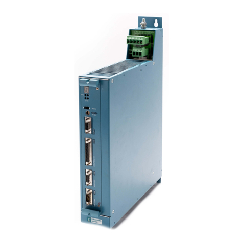
Clinton MINI-TAURUS 990 User manual

SERVICE MANUAL
CLINTON
MODEL 990
MINI-TAURUS
VARIABLE SPEED
DC SERVO MOTOR
NEEDLE POSITIONER THREAD TRIMMER
ML990-1
40-0253-01

SECTION I
PROGRAMMING MODE
There are two ways to go from the operating to the programming mode. Press the button
to go to the first group (SPEEDS). Continue pressing this key to step through the
groups or press the button to go to the last changed parameter.
After changing the parameters press the button to return to the operating mode.
A. HOW TO PROGRAM
1. SPEEDS, TIMERS, COUNTERS
Select the parameter group with the button to the desired parameter
group(exampleSPEEDS).
Select the desired parameter ( example SOFTSTART ) by pressing the button.
Change displayed number with ( increase ) or ( decrease ) button.
2. TOGGLE SWITCHES
Select the parameter group “TOGGLE SWITCHES“ with the button.
Select the desired parameter to be changed with the button.
Toggle the desired parameter with the or button.
B. ACCESS TO HIDDEN PARAMETERS
Step 1: Turn power off.
Step 2: Press the and buttons at the same
time.
Step 3: Turn power on while both buttons are pressed.
Step 4: Release the buttons.
The display shows stars (*****) which are counting down.
Step 5: Press the button before the stars disappear.
Step 6: Select the desiredparameter asusual.
The hidden parameters have stars in front of the group name
Normalparameter:SPEEDS
Hiddenparameter:****SPEEDS
Note: Accessto HIDDEN PARAMETERS is disabledafter power isshut off.
1-1
ML990-2

C. MASTER RESET (Caution:Overridesthe program memory with defaultsettings).
Step 1: Turn power off.
Step 2: Press the , and buttons simultaneously.
Step 3: Turn on power while all three buttons are pressed.
The display alternates between “PUSH SET“ and “FOR RESET".
Step 4: Push the button within 10 cycles.
Thedisplay will read: “PROGRAMMING“.
Note: If the button is not pressed within 10 cycles the program goes to the main
menuwithout executing the MASTERRESET.
ML990-3

SECTION II
EXPLANATION OF PARAMETERS
A. PARAMETERS WITH DIRECT ACCESS
1. SPEEDS (spm,stitchesper minute is the same as R.P.M.)
a. SOFTSTRT (Softstart)
Sets the r.p.m. of the machine while in the soft start option.
(See page 1-3 (3a) and page 1-4 (4c)).
Range: 140 to 2000 r.p.m.
Steps:20 r.p.m.
Defaultsetting:500 r.p.m.
2. TIMERS ( ms = milli seconds )
a. START DEL (Start delay)
This delays the motor from starting in order to allow the presser foot sufficient time to
come completely down before the machine starts sewing. If the presser foot is already
in the down position this setting will not effect the start.
Range: 10 to 500 ms
Steps:10 ms
Default:80 ms
b. VENT DEL (Venturi delay)
This sets the amount of time that the venturi continues to run after the motor has
stopped.
Range: 10 to 2500 ms
Steps:10 ms
Default:350ms
c. WASTErem (Waste Removal)
Sets the amount of time that the venturi is turned off if the waste removal function is
selected.
Range: 10 to 2500 ms
Steps:10 ms
Default:350ms
d. CUTTER
This sets the amount of time that the scissor or guillotine cutter is on.
Range: 50 to 250 ms
Steps:10 ms
Defaultsetting: 80 ms
e. COMPENS. (CUTTERCOMPENSATION)
This parameter is used to compensate for the amount of time needed to fully close a
scissor or guillotine cutter. This parameter needs to be set to the type of cutter being
used so that it will cut accurately at different machine speeds.
Range: 10 to 250 ms
Steps:10 ms
Defaultsetting: 80 ms
2-1
ML990-4

3. COUNTERS
a. SOFT ST (SOFT START)
Sets the number of beginning stitches of a new cycle sewn at “SOFTSTRT“ speed.
(See page 1-2 (1b)).
Range: 1 to 5 stitches
Steps: 1 stitch
Default:3 stitches
b. VENTfrt (Venturi front cut)
This sets the number of stitches sewn with the venturi and chain cutter on once the eye
has been covered at the beginning of the cycle.
Range: 0 to 50 stitches
Steps: 1 stitch
Defaultsetting: 25 stitches
c. VENTend (Venturi end cut)
This sets the number of stitches sewn with the venturi and chain cutter on once the eye
has been uncovered at the end of the cycle.
Range: 1 to 50 stitches
Steps: 1 stitch
Defaultsetting: 30 stitches
d. WASTErem (Wasteremoval)
Sets the number of stitches sewn with the venturi turned on in the seam if the waste
removalfunctionis selected.
Range: 35 to 100 stitches
Steps: 1 stitch
Defaultsetting: 50 stitches
4. TOGGLE SWITCHES (Switches set by software )
a. PF SEAM (Presser foot while in the seam)
This sets the position of the presser foot while sewing in the seam. If "up" is selected the
presser foot will raise every time that the motor stops while in the seam.
Defaultsetting: Down
b. PF EOC ( Presser foot end of cycle)
Sets the position of the presser foot at the end of the cycle.
Defaultsetting: Down
c. SOFTSTRT (SOFT START)
Enables or disables the soft start function.
Default:Off
d. WASTErem (Waste removal)
Enablesor disables the wasteremoval function.
Default:Off
e. POSITION
Sets the needle position while in the seam.
Default:Down
2-2
ML990-5

f. POS. EOC (Position End of Cycle)
Sets the needle position at the end of the cycle.
Default:Up
g. VENTURI
This parameter sets how the chain cutter can be turned on if a cut was missed at the
end of a cycle. If set to "heel bck" the cutter will start by heeling back on the treadle.
If set to "with eye" the cutter will start by breaking the beam of the electric eye.
Default:With eye
B. HIDDEN PARAMETERS
1. **** SPEEDS
a. TRIM / POS
Thisparameter determines the speedof the trim andposition cycle andtheminimum
speedof the machine.
Range: 100 to 400 s.p.m.
Steps:10s.p.m.
Default:220s.p.m.
b. MAXIMUM (Maximum speed). Sets the maximum speed of the machine.
Range: 500 to 9900 r.p.m.
Steps:1000r.p.m.
Default:4200r.p.m.
2. **** MISCEL (Miscellaneous)
a. NEED.dwn (Needledown)
Sets the needle down position. (See TEACH-IN MODE page 3-1)
Range: 0 to 255
Steps: 1
Default:35
b. NEEDLEup (Needleup)
Sets the needle up position. (See TEACH-IN MODE page 3-1)
Range: 0 to 255
Steps: 1
Default:150
c. CLAMP DTY (Clamp duty cycle or percentage of current applied to keep the solenoid
energized). The clamp duty cycle should be set at the minimum value required to keep
the solenoid energized. (a) If the duty cycle value is to low the solenoid will vibrate
(this will cause it to make a chattering noise) and the clamp may drop. (b) If the clamp
duty cycle value is to high the solenoid may get hot and the denergize time will greatly
increase.
Range: 2 to 10
Steps: 1
Default: 4
2-3
ML990-6

3. **** TOGGLE SWITCHES
a. DIRECTION
Sets the direction of the motor either clockwise (++cw) or counterclockwise (--ccw).
Default: --ccw
b. AUTOMODE (Automaticmode)
If set to "AUTO" when material is placed in the machine covering the photo eye and
the treadle is pressed the machine will sew at maximum speed until the photo eye is
uncovered.
Default: man (manual)
c. CYC. STRT (Cycle start)
If selected this parameter will only let the cycle start if the photo eye is covered.
Default: Eye Cov. (Eye Covered)
d. TREADLE
If this parameter is set to;
continue: The new cycle will start depending on the condition of the photo eye
(covered or uncovered) and the setting of the "CYC. STRT" parameter.
ped.neut. (pedal neutral). The new cycle will start only after the pedal has been
returned to the neutral position.
Default: ped. neut
e. SFTY SW (Safety Switch)
This parameter enables or disables the safety switch if one is used.
Default: Off
f. SFTY SW SEW
This parameter sets, whether the safety switch is normally opened or normally
closed, in order for the machine to start.
Default: cls (closed)
2-4
ML990-7A

SECTION III
TEACH-IN MODE
1. SETTING THE NEEDLE-DOWN AND NEEDLE-UP POSITIONS
NOTE:The index signal from the motor must be set prior to setting the needle up and
down positions. ( See systems test section for instruction on setting the index signal ).
a. NEEDLE DOWN
To set the needle down position access the "**** MISC." group of the hidden parameters
then select the "NEED.dwn" parameter. Rotate the hand wheel of the machine until the
needle is in the down position. Press the treadle forward, the machine will make one
revolution then save the needle down position.
b. NEEDLE UP
To set the needle up position access the "**** MISC." group of the hidden parameters
then select the "NEEDLEup" parameter. Rotate the hand wheel of the machine until the
take-up levr is in the top dead center position. Press the treadle foreward, the machine
will make one revolution then save the needle up position.
3-1
ML990-8A

SECTION IV
TEST MODE
A. BUILT-INTEST PROGRAM
A test program is available to test the major functions for proper operation. To access the pro-
gram press the and buttons simultaneously.
The display will read “SYSTEM TEST“ briefly then "PRESS "SET" !!", after which the following
maybe tested:
1.TREADLE
2.EYEANDINDEXSIGNAL
3.ENCODER
4.MOTORBALANCE
1. Treadle Test
Pressthe button until "TEST TREADLE" will be displayed briefly then " NEUTRAL".
a. Move the pedal from neutral to heel 1 then to heel 2.
The display should show each position.
b. Move the pedal forward slowly. As the pedal is moved, a number (0 to 255) will be displayed.
NOTE: This number is proportional to how far the pedal is moved. The lowest number
should be no more than "8" and the highest number greater than "250".
2. Setting the Index Signal
a. Remove the drive belt.
b. Press the button. The display will read "TEST INDEX" briefly then show a broken line
"-----------". If the eye is uncovered the display will show "------Eye------". Rotate the motor by
hand until the display shows "Index-Eye". Rotate the machine by hand until the needle point is
approximately level with the throat plate on it's downward stroke. replace the belt and tighten
with the machine and motor in this position.
3. Encoder Test
CAUTION: Remove the sewing machine belt. The belt has to be removed because the
motor may not develop sufficient torque to turn the machine.
Pressthe button. The display will read "TEST ENCODER" briefly then "PUSH START
(enc)". Press the button the motor will begin to rotate slowly and the display will read
"PLEASE WAIT !!". After 2 or 3 seconds the motor will stop and the display shows the number
of counts. The number should be between 240 and 260 pls.
4-1
ML990-9

3. Motor balance Test
CAUTION: Remove the sewing machine belt.
Press the button. The display will read "CHECK BALANCE" briefly then "PUSH START
(bal)". Press the button the motor will begin to rotate slowly in one direction and then the
other, the display will read "PLEASE WAIT !!". When the motor stops the display will show a
balance number ( 0-255 ). The balance number should be below 10.
NOTE: If the motor is to far out of balance the display may read "DIRECTION FAILED". This
error message will also occur if the motor is unplugged from the control box when the balance is
beingtested.
4-2
ML990-10

SECTION V
CONNECTOR DIAGRAMS
Listed below are the pinouts for the Model 990 control box connectors.
NO. TOTAL PINS CONNECTOR PIN NO. FUNCTION
1 6 SYNCHRONIZER 1
2
3
4
5
6
+5
DOWN SENSOR
UP SENSOR
TRIM SENSOR
GND
LED
2 6 AUX INPUTS 1
2
3
4
5
6
+5
GND
CHASSIS GND
I 1
I 2
I 3
3 4 AUX OUTPUTS 1
2
3
4
+48 V
R1
+48 V
R2
4 2 FOOTLIFT 1
2FOOTLIFT SOL.
+48V
5 9 TRIM, WIPER,
BACKTACK
SOLENOIDS, AND
MANUAL BACKTACK
SW.
1
4
2
5
3
6
7
8
9
WIPER SOL. -
WIPER SOL. +(48V)
TRIMMER SOL. -
TRIMMER SOL. +(48V)
BACKTACK SOL. -
BACKTACK SOL. +(48V)
+ MANUAL BACK
- TACK SWITCH
NOT USED
5-1
ML990-11

5-2
ML990-12
NO. TOTAL PINS CONNECTOR PIN NO. FUNCTION
6 8 ENCODER 1
2
3
4
5
6
7
8
+5V
ENCODER (S1)
ENCODER (S2)
SIG. GND
PHASE C
PHASE B
PHASE A
INDEX
716 LCD DISPLAY 1
2
3
4
5
6
7
8
9
10
11
12
13
14
15
16
EXT1
CHASSIS GND
+5V
GND
D0
D1
D2
D3
D4
D5
D6
D7
CA1
E
ERD
CA0
8 4 AC POWER 220V 3 1
2
3
4
PHASE A
PHASE B
PHASE C
CHASSIS GND
9 4 MOTOR VOLTAGE 1
2
3
4
PHASE A
PHASE B
PHASE C
CHASSIS GND

NO. TOTAL PINS CONNECTOR PIN NO. FUNCTION
612 NOTUSED - -
712 NOTUSED - -
8 8 COMMUTATOR 1
2
3
4
5
6
7
8
+5V
ENCODER (S1)
ENCODER (S2)
SIG.GND
PHASEC
PHASEB
PHASEA
-5V
916 LCDDISPLAY 1
2
3
4
5
6
7
8
9
10
11
12
13
14
15
16
EXT1
CHASSISGND
+5V
GND
D0
D1
D2
D3
D4
D5
D6
D7
CA1
E
ERD
CA0
10 4AC POWER 220V 3 1
2
3
4
PHASEA
PHASEB
PHASEC
CHASSISGND
11 4MOTORVOLTAGE 1
2
3
4
PHASEA
PHASEB
PHASEC
CHASSISGND


Table of contents
Popular Servo Drive manuals by other brands
Danfoss
Danfoss 176F6491 installation instructions
Festo
Festo CMMT-ST-C8-1C-...-S0 Series Original instructions
Triamec
Triamec TSD350-10 Hardware manual
Kingservo
Kingservo KSDG Series manual
Mitsubishi Electric
Mitsubishi Electric TM-RFM instruction manual
Allen-Bradley
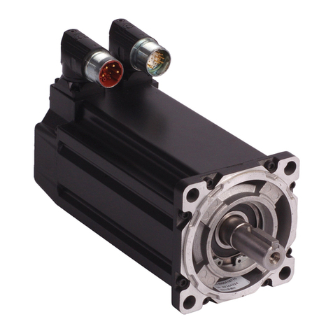
Allen-Bradley MP-Series installation instructions
