EMIS EMIS-BAR 103 User manual

www.emis-kip.ru
EB 100.000.00 OM
01.12.2020
V2.0.15-01
Pressure transmitters
EMIS-BAR
Operation manual
High accuracy
Accuracy does not
depend on process
parameters
Ex-proof application
LCD display
In-built self-check
EMIS CJSC
Russia, Chelyabinsk

EMIS-BAR
OPERATION MANUAL
2
1 DESCRIPTION AND OPERATION
4
1.1 Application
4
1.2 Specification
4
1.3 Explosion protection
11
1.4 Configuration and operation
14
1.5 Pressure transmitter adjustment
15
1.6 Operation via HART protocol
25
1.7 Error log
25
1.8 Supply scope
26
1.9 Marking and sealing
26
1.10 Package
27
2 APPLICATION
28
2.1 Operating features
28
2.2 Mounting requirements
29
2.3 Operation
30
2.4 Connection to HART
31
3 MAINTENANCE AND REPAIR
32
4 CALIBRATION
32
5 LIST OF POSSIBLE FAILURES
32
6 PERSONELL ACTIONS IN CASE OF ACCIDENT, CRITICAL FAILURE OR BREAKDOWN
34
7LIMIT STATE CRITERIA
34
8 STORAGE
34
9 TRANSPORTATION
34
10 RECYCLING
34
11 PRECIOUS MATERIALS CONTENT
34
Appendix A List of reference documents
35
Appendix B Connection schemes
36
Appendix C Order sheet EMIS-BAR pressure transmitters
38
Appendix D Mounting kit order sheet
52
Appendix EDimensions and connection sizes of pressure transmitters
57
Dimensions and connection sizes of flanges
71
Appendix FMounting kit
75
Appendix G Explosion protection scheme
81
Appendix H Installation on a bracket
83
Appendix I List of cable glands
85

EMIS-BAR
OPERATION MANUAL
3
Present Manual is used for studying the structure, operation, operating rules, maintenance and
calibration of the pressure transmitters EMIS-BAR.
This operation manual contains general technical parameters, directions for usage, calibration,
transportation and storage, and other information to ensure correct operation of the pressure transmit-
ter. The design of the transmitter is constantly being improved, so the device you purchased may
have minor differences from the description given in this document which do not affect the perfor-
mance, technical characteristics and usability.
Any use of the trade marks and present manual, partial or full, is prohibited without copyright
holder permission.
Manufacturer has the right to update the product and documents without prior notice if it does
not affect product performance.
Symbols and abbreviations
The following abbreviations are used in this document:
ADC - analog to digital converter;
DAC - digital to analog converter;
CPU - central processing unit;
LCD - liquid crystal display;
SCS - state calibration system;
CS - checksum;
SW - device software;
DDL - Device Description Language for HART. Is used to define and describe the device and
then read device data during digital communication;
DD - Device Description is a PC software written in DDL;
RFI - radio interference filter. Serve to eliminate the influence of electromagnetic interference
on the transmitter readings.

EMIS-BAR
OPERATION MANUAL
4
1DESCRIPTION AND OPERATION
1.1 Application
1.1.1 EMIS-BAR pressure transmitters (hereinafter "transmitters") are designed for continu-
ous measurement of pressure (gauge, vacuum, absolute, hydrostatic and differential (pressure differ-
ence)) and conversion of the measured pressure into a rated DC output signal 4-20 mA overlapped
with digital HART signal, as well as displaying the measured value on the display.
EMIS-BAR pressure transmitters can be used in automatic control, adjustment and operation
systems at various industries.
1.1.2 Transmitters can be operated and adjusted using an inbuilt keyboard or remotely using
HART-compatible device.
1.1.3 Transmitters with HART can transfer information about measuring value in digital form
via the 2-wire connection line along with 4-20 mA current signal. Digital signal can be received and
converted by any HART-compatible device. Digital output is used to connect transmitter with portable
HART communicator or PC via standard serial interface and additional HART modem. The following
operation can be executed: setup transmitter, select main parameters, read measured pressure, etc.
HART-protocol allows two master devices be connected to the system: HART-compatible PC and
portable HART communicator. Transmitter can receive and execute commands of each of the control
devices with different addresses and exchanging data in the time sharing mode.
Measured value is displayed in selected units on the transmitter indicator or HART communi-
cator in measuring mode.
1.1.4 Transmitter meets the requirements of the technical regulations: TR CU 020/2011, TR
CU 032/2013.
1.1.5 Transmitter can be used for both safe and explosive environments.
Ex-proof transmitters comply with the technical regulations TR CU 012/2011.
Ex-proof transmitter intended for use in explosive environment of premises and outdoor instal-
lations according to GOST IEC 60079-14 as given in the chapter 7.3 of the Russian Electrical Code
and other normative documents designed for explosive environments.
Transmitters of Exd and RV configurations have flameproof enclosure "d" under GOST IEC
60079-1-2011, ex-proof design and intended for use in explosive environments hazardous with gas
mixtures and vapours of I, IIB, IIC, IIIB иIIIC categories.
Transmitters of ЕхiaC, ExiaB and RO configurations have explosion protection "intrinsically
safe circuit "i" under GOST 31610.11-2014, with increased explosion protection and intended for use
in explosive environments hazardous with gas mixtures and vapours with oxygen of I, IIB, IIC, IIIB,
IIIC categories.
Transmitters of Exdia and RVia configurations have explosion protection "flameproof enclo-
sure "d" under GOST IEC 60079-1-2011 and "intrinsically safe circuit "i" under GOST 31610.11-
2014, intended for use in explosive environments hazardous with gas mixtures and vapours with oxy-
gen of IIC category. Exdia configuration has protection level "increased flame protection". RVia con-
figuration has protection level "flameproof".
1.1.6 Please specify transmitter symbolic designation when placing order. Use Annex C for
reference.
If transmitter is mentioned in the documents related to other products, the following shall be
specified:
- transmitter symbolic designation;
- technical parameters: TU 26.51.52-080-14145564-2018.
1.1.7 See Annex D for mounting kit order codes. Drawings and mounting kit are shown in the
Annex F.
1.2 Specification
1.2.1 Type of measurement pressure, transmitter model, order codes, full range of pressure meas-
urement, min 𝑃𝑢 𝑚𝑖𝑛 and max 𝑃𝑢 𝑚𝑎𝑥 limit of measurement are specified in the Table 1.2.
1.2.2 Measurement range and upper limit can be adjusted to required values from 𝑃𝑙 𝑚𝑖𝑛 to
𝑃𝑢 𝑚𝑎𝑥, as provided in the Tables 1 and 2.

EMIS-BAR
OPERATION MANUAL
5
1.2.3 Overload pressure for absolute pressure and gauge pressure transmitters is specified in
the Table 1.
1.2.4 Overload working pressure limit for differential and level pressure transmitters is speci-
fied in the Table 2.
Table 1 –Measuring ranges of gauge and absolute pressure transmitters
Type of
measurement
pressure
Transmitter
model
Order code
Full
range
of measurement
Min upper level
𝑃𝑢 𝑚𝑖𝑛
Max upper level
of measurement
𝑃𝑢 𝑚𝑎𝑥
Overload
pressure, Mpa
Range
adjustment
Gauge
pressure
103
(-100…100) kPa
-100…100 kPa
5 kPa
100 kPa
0.6
1:20
(-100…400) kPa
-100…400 kPa
10 kPa
400 kPa
1
1:40
(-0.1…1.6) MPa
-0.1…1.6 MPa
16 kPa
1,6 MPa
3.2
1:100
(-0.1…6.3) MPa
-0.1…6.3 MPa
63 kPa
6,3 MPa
10
1:100
(-0.1…16) MPa
-0.1…16 MPa
160 kPa
16 MPa
25
1:100
(-0.1…40) MPa
-0.1…40 MPa
400 kPa
40 MPa
60
1:100
105
(-100…100) kPa
-100…100 kPa
5kPa
100 kPa
0.6
1:20
(-100…400) kPa
-100…400 kPa
10 kPa
400 kPa
1
1:40
(-0.1…1.6) MPa
-0.1…1.6 MPa
16 kPa
1,6 MPa
3.2
1:100
(-0.1…6.3) MPa
-0.1…6.3MPa
63 kPa
6.3 MPa
10
1:100
(-0.1…16) MPa
-0.1…16 MPa
160 kPa
16 MPa
25
1:100
113
(0…100) kPa
0…100 kPa
10 kPa
100 kPa
0.6
1:10
(0…400) kPa
0…400 kPa
40 kPa
400 kPa
1
1:10
(0…1.6) MPa
0…1.6 MPa
160 kPa
1.6 MPa
3.2
1:10
(0…6.3) MPa
0…6.3 MPa
630 kPa
6.3 MPa
10
1:10
173
174
(-100…100) kPa
-100…100 kPa
5 kPa
100 kPa
0.6
1:20
(-100…400) kPa
-100…400 kPa
20 kPa
400 kPa
1
1:20
(-0.1…1.6) MPa
-0.1…1.6 MPa
80 kPa
1.6 MPa
3.2
1:20
(-0.1…6.3) MPa
-0.1…6.3 MPa
320 kPa
6.3 MPa
10
1:20
(-0.1…16) MPa
-0.1…16 MPa
800 kPa
16 MPa
25
1:20
(-0.1…40) MPa
-0.1…40 MPa
2 MPa
40 MPa
60
1:20
Absolute
pressure
123
(0…25) kPa
0…25 kPa
0.83 kPa
25 kPa
0.6
1:30
(0…130) kPa
0…130 kPa
4.3 kPa
130 kPa
1
1:30
(0…500) kPa
0…500 kPa
16 kPa
500 kPa
3.2
1:30
(0…3) MPa
0…3 MPa
100 kPa
3 MPa
10
1:30
(0…16) MPa
0…16 MPa
600 kPa
16 MPa
25
1:25
(0…40) MPa
0…40 MPa
1.4 MPa
40 MPa
60
1:28

EMIS-BAR
OPERATION MANUAL
6
Table 1 continued
Type of
measurement
pressure
Model
Order code
Full
range
of measurement
Max upper level
of measurement
𝑃𝑢 𝑚𝑖𝑛
Max upper level
of measurement
𝑃𝑢 𝑚𝑎𝑥
Overload
pressure, Mpa
Range
adjustment
Absolute
pressure
133
(0…25) kPa
0…25 kPa
0.83 kPa
25 kPa
3.2
1:30
(0…130) kPa
0…130 kPa
4.3 kPa
130 kPa
3.2
1:30
(0…500) kPa
0…500 kPa
16 kPa
500 kPa
3.2
1:30
(0…3) MPa
0…3 MPa
100 kPa
3 MPa
16
1:30
(0…10) MPa
0…10 MPa
530 kPa
10 MPa
25
1:18
175
176
(0…25) kPa
0…25 kPa
5 kPa
25 kPa
0,6
1:5
(0…130) kPa
0…130 kPa
10 kPa
130 kPa
1
1:13
(0…500) kPa
0…500 kPa
25 kPa
500 kPa
3.2
1:20
(0…3) MPa
0…3 MPa
150 kPa
3 MPa
10
1:20
(0…16) MPa
0…16 MPa
600 kPa
16 MPa
25
1:26
(0…40) MPa
0…40 MPa
1.4 MPa
40 MPa
60
1:28
Table 2 –Measuring ranges of differential and hydrostatic pressure transmitters
Type of
measurement
pressure
Model
Order code
Full
measuring range
Max upper level
of measurement
𝑃𝑢 𝑚𝑖𝑛
Max upper level
of measurement
𝑃𝑢 𝑚𝑎𝑥
Overload working
pressure, MPa
Range adjustment
Differential
pressure
143
(-25…25)kPa
-25…25 kPa
1 kPa
25 kPa
16
1:25
(-60…60)kPa
-60…60 kPa
1 kPa
60 kPa
16
1:60
(-160…160)kPa
-160…160 kPa
1.6 kPa
160 kPa
16
1:100
(-500…500)kPa
-500…500 kPa
5kPa
500 kPa
16
1:100
(-0.5…3)MPa
-0.5…3 MPa
30 kPa
3 MPa
16
1:100

EMIS-BAR
OPERATION MANUAL
7
Table 2 continued
Type of
measurement
pressure
Model
Order code
Full
measuring range
Max upper level
of measurement
𝑃𝑢 𝑚𝑖𝑛
Max upper level
of measurement
𝑃𝑢 𝑚𝑎𝑥
Overload working
pressure, MPa
Range adjustment
Differential
pressure
183
184
185
186
187
188
(-25…25) kPa
-25…25 kPa
2.5 kPa
25 kPa
0.6
1:10
(-60…60) kPa
-60…60 kPa
3 kPa
60 kPa
1
1:20
(-160…160) kPa
-160…160 kPa
8 kPa
160 kPa
3.2
1:20
(-500…500) kPa
-500…500 kPa
25 kPa
500 kPa
10
1:20
(-0,5…3) MPa
-0.5…3 MPa
150 kPa
3 MPa
16
1:20
193
(-2…2) kPa
-2…2 kPa
0.1 kPa
2 kPa
0.2
1:20
Hydrostatic
pressure
163
164
(-10…10) kPa
-10…10 kPa
2 kPa
10 kPa
Depends
on flange
size
See Table.
C.3
1:5
(-25…25) kPa
-25…25 kPa
2.5 kPa
25 kPa
1:10
(-60…60) kPa
-60…60 kPa
2.5 kPa
60 kPa
1:24
(-160…160) kPa
-160…160 kPa
5.3 kPa
160 kPa
1:30
(-500…500) kPa
-500…500 kPa
16 kPa
500 kPa
1:30
(-0,5…3) MPa
-0,5…3 MPa
100kPa
3 MPa
1:30
1.2.5 The limits of the permissible basic reduced error 𝛾for models with an analog output
signal expressed as percentage of the upper limit or output signal measurement range do not exceed the
values shown in the Tables 3-4.
Table 3 - Limits of the permissible basic reduced error for transmitters with analog output sig-
nal
The limits of the permissible basic reduced error depending on the coefficient
of adjustment of the measuring range 𝛾,%
Application based on the
model
r≤10
10 < r ≤ 30
30 < r ≤ 100**
±0.04
±(0.004· r)
-
103, 105, 113, 123, 133,
143
±0.065
±(0.0065·r)
±(0.005·r+0.071)
±0.074
±(0.0074·r)
-
163, 164
±0.1; ±0.15; ±0.2;
±0.25; ±0.4; ±0.5;
±1.0
±(ɣ/10·r)
±(ɣ/10·r+0.071)
103, 105, 113, 123, 133,
143, 163, 164
Note
r - coefficient of adjustment of the measuring range of the pressure transmitter, calculated using the
formula: 𝑟=𝑃в 𝑚𝑎𝑥
𝛥𝑃
where ΔР=Рu -Рl–new measuring range of transmitter.
** r adjustment from 30 to 100 is possible only for models 103, 105 and 143.

EMIS-BAR
OPERATION MANUAL
8
Table 4 - Limits of the permissible basic reduced error γfor transmitters with analog output sig-
nal
The limits of the permissible basic reduced error depending on the
measuring range adjustment coefficient. 𝛾, %
Application based on the
model
r ≤ 5
5 < r ≤ 20
±0.086
±(0.071+0.0029·r)
193
±(0.09+0.01·r)
±(0.09+0.012·r)
173, 174
±0.15; ±0.2; ±0.25; ±0.4; ±0.5; ±1.0
±(0.09+ ɣ/10·r)
±0.15
±(0.09+0.012·r)
175, 176, 183, 184, 185,
186, 187, 188, 193
±0.2; ±0.25; ±0.4; ±0.5; ±1.0
±(0.09+ ɣ/10·r)
1.2.6 The limits of the permissible basic reduced error 𝛾for models with digital output signal
expressed as percentage of the upper limit or output signal measurement range do not exceed the val-
ues shown in the Table 5.
Table 5 - Limits of the permissible basic reduced error for transmitters with digital output signal
Limits of the permissible basic reduced error 𝛾, %
Application based on the
model
±0.04; ±0.065
103, 105, 113, 123, 133,
143
±0.074
163, 164
±0.1; ±0.15; ±0.2; ±0.25; ±0.4; ±0.5; ±1.0
103, 105, 113, 123, 133,
143, 163, 164, 173, 174
±0.086
193
±0.15; ±0.2; ±0.25; ±0.4; ±0.5; ±1.0
175, 176, 183, 184, 185,
186, 187, 188, 193
1.2.7 Output signal variability 𝛾Г, does not exceed absolute limit of the permissible basic re-
duced error |𝛾|.
1.2.8 Output signal ripple in the range from 0,06 to 5Hz does not exceed 0,7|𝛾|.
Analog signal ripple in the range from 5 to 106Hz shall not exceed 0,55% of the measuring
range. Analog signal ripple higher than 106Hz is not rated. Output signal ripple is rated at load re-
sistance of 250 Ohm (in the absence of communication with the transmitter via HART).
Note: signal ripple is rated at minimum averaging time of the measuring results.
1.2.9 Output signal is linear dependent or proportional to square root of the input measuring
value.
1.2.10 The nominal static characteristic of the transmitter with a linearly increasing depend-
ence of the analog output signal on the input measuring value corresponds to:
𝐼=𝐼н+𝐼в− 𝐼н
𝑃в−𝑃н×(𝑃−𝑃н)
(1)
where 𝐼–current value of the output signal, mA;
Р–measured value in stated units;
𝐼н= 4 mA, 𝐼в= 20 mA –upper and lower limits of the output signal, respectively.
𝑃в, 𝑃н- respectively, upper and lower limits of the output signal in stated units.
The nominal static characteristic of the transmitter with a linearly decreasing dependence of the
analog output signal on the input measuring value corresponds to:
𝐼=𝐼в−𝐼в− 𝐼н
𝑃в−𝑃н×(𝑃−𝑃н)
(2)
The nominal static characteristic of the transmitter with the function of converting the input
measured value according to the square root law corresponds to:

EMIS-BAR
OPERATION MANUAL
9
𝐼=𝐼н+(𝐼в− 𝐼н)×√𝑃−𝑃н
𝑃в−𝑃н
(3)
where 𝑃–input measured value - pressure difference in stated units.
1.2.11 General purpose industrial transmitter and ex-proof version with protection type "flame-
proof enclosure" shall be connected to 10.5 to 45VDC supply unit.
1.2.12 Ex-proof version with protection type "intrinsically safe electrical circuit "i" shall be con-
nected to 10.5 to 28VDC supply unit.
1.2.13 Electrical wiring diagrams are given in the Annex B.
1.2.14 Power consumption not exceed 1,0 V-A (0,65 V·A for versions ExiaC, ExiaB, RO, RVia
and Exdia).
1.2.15 The limits of the permissible load resistance (resistance of transmitter and communication
lines) depends on the stated transmitter supply voltage and should not go beyond the boundaries of the
working area shown in Figure 1 in the range from 𝑅𝑚𝑖𝑛 to 𝑅𝑚𝑎𝑥.
Fig.1 - Graph of dependence between the load resistor resistance and transmitter supply voltage
𝑅𝑚𝑎𝑥 are calculated as below:
𝑅𝑚𝑎𝑥 =𝑈−10,5
0,023
(4)
where U - transmitter supply power, V.
𝑅𝑚𝑖𝑛 =0 if HART signal is not available.
𝑅𝑚𝑖𝑛 =230 Ohm if using HART communication.
1.2.16 Transmitter has electronic damping of the output signal, which represents measuring re-
sults averaging time. Time range can be selected from the range: 0.1 s; 0.5 s; 1 s; 2.5 s; 5 s; 10 s; 20 s;
50 s; 100 s. Averaging time of measurement influence output signal detection time.
1.2.17 Response time of the transmitter shall not exceed 100ms.
1.2.18 Saturation current when measured value goes beyond the stated limits:
3.8 mA - measured value lower than stated lower limit;
20.5 mA - measured value higher than stated upper limit.
1.2.19 The transmitters are protected against reverse polarity of the supply voltage.
1.2.20 Ambient temperature range for general industrial transmitters, including LCD versions,
from -60° to +85°С. Ambient temperature range for ex-proof transmitters, including LCD versions, is
specified in the Table 9.

EMIS-BAR
OPERATION MANUAL
10
1.2.21 Additional reduced error ɣtcaused by ambient temperature changes within working
temperature range does not exceed the values given in the Table 6 for each 10°С.
Table 6 - Limits of additional reduced error ɣt
Additional reduced error to the measuring range caused by changes in
ambient temperature ɣt, %
Application based on the
model
with analog output
±(0.023·r+0.02)
103, 105, 113, 123, 133, 143
±(0.04·r+0.04)
163..188
±(0.046·r+0.04)
193
for versions with digital output signal
±0.043
103, 105, 113, 123, 133, 143
±0.08
163..188
±0.086
193
1.2.22 Medium temperature range from - 40° to +120°С for pressure transmitters models 103,
105, 113, 123, 133, 143, 163, 164, 193. For models 173...188 temperature range depends on the oper-
ating temperature of the liquid in capillaries ("Capillaries liquid" in the order line).
1.2.23 The transmitters are resistant to 95 ± 5% relative humidity at +35 ° C and lower temper-
atures with moisture condensation.
1.2.24 In terms of resistance to the effects of environmental factors, pressure transmitters can
be operated in boreal climates location class 1 under GOST 15150.
1.2.25 Transmitter is resistant to external magnetic field up to 400 A/m under GOST Р 50648 (IEC
1000-4-8-93).
1.2.26 Transmitter is resistant to industrial radio interference:
GOST R 51317.4.4 3rd test severity level.
GOST R 51317.4.3 3rd test severity level at 80-1000 MHz
GOST R 51317.4.2 4th test severity level.
GOST R 51317.4.6 2nd and 3rd test severity level with HART test operated under noises.
GOST R 50648 5th test severity level.
GOST R 50649 5th test severity level.
GOST R 50652 5th test severity level.
GOST R 51317.4.5 2nd test severity level "wire-to-wire" interference and 3rd test severity
level "wire-to-ground" interference. Interference resistance - A
1.2.27 The transmitters comply with the emission standards established for class B by
GOST R 51318.11.
1.2.28 Transmitter protection against dust and water comply with IP65, IP66, IP67, IP68 un-
der GOST14254, and depends on selected cable gland or plug adapter according to the Annex I.
1.2.29 Average service life is at least 30 years, provided proper maintenance and normal op-
erating conditions:
- environment temperature plus (23±10)ºС;
- relative humidity from 20 to 95%;
- atmospheric pressure from 84 to 105.7 kPa;
- power supply 24±0,5V DC;
- no external electrical and magnetic fields (except for earth) influence device operation;
- no vibration, shaking, bumps affecting the operation of the transmitter;
- non-corrosive medium.

EMIS-BAR
OPERATION MANUAL
11
1.2.30 Mean time before failure shall not be less than 150000 hours and depends on mainte-
nance as specified in the manual;
1.2.31 Transmitters are resistant to vibrations with frequency 10 to 2000Hz and acceleration
not exceeding 98m/s2, refers to G2 group under GOST R 52931-2008.
1.2.32 Pressure transmitters are earthquake resistant if exposed to earthquakes with an inten-
sity of 9 points on the MSK-64 scale.
1.2.33 Dimensions and connection size of pressure transmitter with mounting kit are show in
the Annex E.
1.2.34 Transmitters are equipped with protection unit (LP code as additional option) against
transient phenomena in communication lines caused by lightning, welding, the operation of powerful
electrical equipment and switching mechanisms.
1.2.35 Transmitters with LCD can be adjusted using inbuilt control functions.
1.2.36 Transmitters without LCD can be adjusted via HART compatible control unit.
1.2.37 Transmitter service life is 15 years provided that transmitter is made of corrosion re-
sistant materials.
1.2.38 For transmitters with remote diaphragm seal bending of capillary lines with a radius of
not less than 5 cm is allowed. The material of the capillaries is 316 stainless steel.
1.2.39 Transmitter body is equipped with ground clamp and marked with earth sign under
GOST 21130.
1.2.40 Transmitter parts materials which contact measuring medium are specified in the
Annex C.
1.2.41 Transmitter weight does not exceed the values specified in the Table 7.
Table 7 - Transmitter weight
Transmitter model
Weight, kg, not more than
103, 123,
1.6
113
1.8
105, 133, 143, 193
3.6
163, 164
3.6 without flanges
173, 174, 175, 176
1.6 without flanges
183, 184, 185, 186, 187, 188
3.6 without flanges
1.3 Explosion protection
1.3.1 Explosion protection "intrinsically safe circuit "i" under GOST 31610-11-2012 is pro-
vided by the following means:
- power supply shall be provided from intrinsically safe unit with output circuits of "ia" level and
electrical parameters complying with GOST 31610.11-2014 for intrinsically safe circuits of electrical
equipment operated in explosive environment;
- connection of external devices to digital, current outputs shall be provided via intrinsically safe
barriers with output circuits of "ia" level and electrical parameters complying with GOST 31610.11-
2014 for intrinsically safe electrical circuits of equipment operated in explosive environment.
- electrical load on active and passive elements of intrinsically circuits shall not exceed 2/3 of the
stated value;
- leakage path, clearance and insulation strength, electrical parameters of circuit boards and con-
nections comply with GOST 31610.11-2014;
- internal capacity and inductance of the electrical circuit do not accumulate energy, explosive
gas mixtures complying with explosive operating conditions;
- insulation of the circuit against the body and between the intrinsically safe circuit and the body
or grounded part of the transmitter withstands the testing voltage not less than 500V AC;

EMIS-BAR
OPERATION MANUAL
12
- current- carrying connections and electronic components are protected against environmental
exposure with IP67 (IP68) enclosure complying with GOST 14254.
For ЕхiaC, ExiaB, Exdia, RO, RVia versions input parameters of supply circuit and output signal
circuits are shown in the Table 8.
Table 8 - Supply circuit input parameters for ЕхiaC, ExiaB, Exdia, RO, RVia versions
Parameter
Parameter value for current circuit
Input voltage range Ui, V
12 to 28
Input current Ii, mA, not exceeding
100
Input power Pi, W, not exceeding
0.7
Internal capacity Ci, nF, not exceeding
30
Internal inductance Li, µH, not exceeding
0.6
1.3.2 Explosion protection "flameproof enclosure "d" under GOST IEC 60079-1-2011 is pro-
vided by the following means:
Electrical elements are covered with ex-proof enclosure to prevent from explosion pres-
sure and transfer of fire to the explosive environment.
flameproof enclosures comply with GOST IEC 60079-1-2011;
flameproof connections comply with GOST IEC 60079-1-2011;
tolerances and length of the planar and cylindrical explosion-proof joints comply with
the GOST IEC 60079-1-2011;
mechanical performance of enclosure complies with GOST 31610.0-2014 (IEC 60079-
0:2011);
warning signs on the cover: "Switch off before open in explosive environment".
Exd transmitters shall be equipped with Ex-proof cable glands and Ex-proof plugs complying
with "d" type of explosion protection for IIC sub-group, environment temperature for T6 version of
transmitter and ingress protection not lower than IP67 under GOST 14254-2015.
1.3.3 Transmitter protection against explosive dust is ensured by "flameproof enclosure "t"
complying with GOST IEC 60079-31-2013.
1.3.4 Ex-proof transmitters have an additional plate with the explosion protection marking in-
dicated in the Table 9.
Table 9 - Ex-proof marking
Ex-proof transmitters
Marking
Exd
1Ex d IIC T4 Gb X Ex tb IIIC 135°C Db
- 60 ≤ ta≤ + 85 °C
1Ex d IIC T5 Gb X Ex tb IIIC 100°C Db
- 60 ≤ ta≤ + 85 °C
1Ex d IIC T6 Gb X Ex tb IIIC 85°C Db
- 60 ≤ ta≤ + 70 °C
ExiaC
0Ex ia IIC T4 Ga X Ex ia IIIC 135°C Da
- 60 ≤ ta≤ + 85 0C
Ui≤ 28 В, li≤ 100 mA, Pi ≤ 0,7 W,
Ci= 30 nF, Li= 0,6 µH
0Ex ia IIC T5 Ga X Ex ia IIIC 100°C Da
- 60 ≤ ta≤ + 85 0C
Ui≤ 28 В, li≤ 100 mA, Pi ≤ 0,7 W,
Ci= 30 nF, Li= 0,6 µH
0Ex ia IIC T6 Ga X Ex ia IIIC 85°C Da
- 60 ≤ ta≤ +70 0C
Ui≤ 28 В, li≤ 100 mA, Pi ≤ 0,7 W,
Ci= 30 nF, Li= 0,6 µH

EMIS-BAR
OPERATION MANUAL
13
ExiaB
0Ex ia IIB T4 Ga X Ex ia IIIB 135°C Da
- 60 ≤ ta≤ + 85 0C
Ui≤ 28 В, li≤ 100 mA, Pi ≤ 0,7 W,
Ci= 30 nF, Li= 0,6 µH
0Ex ia IIB T5 Ga X Ex ia IIIB 95°C Da
- 60 ≤ ta≤ + 85 0C
Ui≤ 28 V, li≤ 100 mA, Pi ≤ 0,7 W, Ci= 30 nF, Li= 0,6 µH
0 Ex ia IIB T6 Ga X Ex ia IIIB 80°C Da
- 60 ≤ ta≤ + 70 0C
Ui≤ 28 V, li≤ 100 mA, Pi ≤ 0,7 W, Ci= 30 nF, Li= 0,6 µH
Exdia
1Ex d ia IIC T4 Gb X
- 60 ≤ ta≤ + 85 °C
Ui≤ 28 V, li≤ 100 mA, Pi ≤ 0,7 W, Ci= 30 nF, Li= 0,6 µH
1Ex d ia IIC T5 Gb X
- 60 ≤ ta≤ + 85 °C
Ui≤ 28 V, li≤ 100 mA, Pi ≤ 0,7 W, Ci= 30 nF, Li= 0,6 µH
-
1Ex d ia IIC T6 Gb X
- 60 ≤ ta≤ + 70 °C
Ui≤ 28 V, li≤ 100 mA, Pi ≤ 0,7 W, Ci= 30 nF, Li= 0,6 µH
RV
РВ Ex d I Mb X
- 60 ≤ ta≤ + 70 °C
RO
РО Ex ia I Ma X
- 60 ≤ ta≤ + 70 °C
RVia
РВ Ex d ia I Mb X
- 60 ≤ ta≤ + 70 °C
The body of RV, RO, RVia ex-proof transmitter versions operated in underground mines and
pits and its overground facilities hazardous with gas and dust are made of stainless steel.
ATTENTION:
during operation it is necessary to take measures of protection against excess temperature of the
transmitter elements due to heating from the measured medium above the value acceptable for the tem-
perature class T6 ... T4;
painted transmitters can present a risk of potential electrostatic charge. Wipe only with wet or
antistatic cloth;
close transmitter cover before switch it on;
the explosion protection is valid for the medium pressure below the maximum level permitted
for that type of transmitter.
EMIS-BAR
OPERATION MANUAL
14
1.4 Configuration and operation
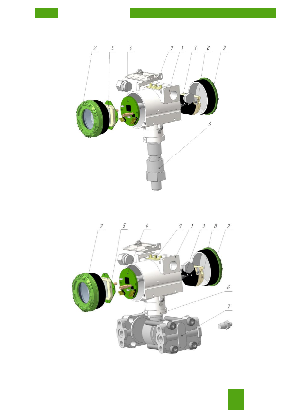
1.4.1 Transmitter structure is shown in the fig.2.
a) Transmitter with in-line mount connection
b) Transmitter with traditional mount connection
Fig.2 - Pressure transmitter structure

EMIS-BAR
OPERATION MANUAL
15
Pressure transmitter consists of pressure sensor and electronic unit (fig.2). Electronic unit is at-
tached to the threaded socket of the pressure sensor. Transmitter includes: electronic board (4), sealed
covers (2), LCD unit (5), RFI filters (3), terminal board (8), adjusting buttons (9).
The difference between the in-line mount and the traditional mount versions is in the design of
the pressure sensor (6). For in-line mount version, the pressure transmitter consists of a housing and a
socket, where the sensor and measuring diaphragm are located. For traditional mount version, the pres-
sure transmitter consists of the sensor with measuring diaphragms located at the positive side (high
pressure side) and the negative side (low pressure), flanges (7) and fasteners.
1.4.2 The transmitter work is based on a piezoresistive method of pressure measurement, which
is based on measuring the voltage difference across the resistances of the bridge circuit of an integrated
sensitive element made of single-crystal silicon under mechanical action. Sensor is fixed on the silicon
lining, which itself fixed on the measuring diaphragm. When the pressure of the working medium
changes, the geometry of the resistances of the Wheatstone bridge and the potential difference at its
outputs change. After double conversion of an analog-digital and digital-analog signal in the electronic
unit, amplification, filtering, modulation, the current signal at the output is proportional to the change in
the pressure of medium.
1.4.3 The structure allows to rotate transmitter for 270° around the common vertical axis, while
the rotation angle is limited to the design of the rotation assembly (fig.3).
After rotation is done, tighten the lock screw to avoid accidental rotation.
270º
Fig.3 - Transmitter rotation angle
1.4.4 LCD can be rotated for 360° with fixation at each 90° for convenient reading. To rotate
transmitter follow the steps below: unscrew two screws, pull up the display, rotate and put it back down,
screw two screws.
1.5 Pressure transmitter adjustment
1.5.1 To adjust the transmitter use the input buttons (fig. 4) located at the transmitter body.
The control unit is installed in the upper part of the housing and allows you to adjust the trans-
mitter in the hazardous area without violating the seal of the transmitter casing.
To access the buttons unscrew two screws in the upper side of the casing and fold back the plas-
tic cover. Use M button to navigate and «↑» and«↓» to change. To save changes in the nonvolatile de-
vice memory simultaneously press «↑» and «↓» buttons. After that Save will appear in the lower line of
the display.
Lock screw

EMIS-BAR
OPERATION MANUAL
16
Figure 4 - Input buttons
Follow the operating rules below:
To configure the device using the keyboard, unlock the input buttons.
The digital parameters of the device are always changed by successively increasing the value,
starting from the lowest digit of the displayed parameter Hold «↑» or «↓» to transfer to next digit. This is
used for rough adjustment within the wide range. For accurate adjustment release button «↑» or «↓»,then
press it again.
Any write commands via HART are disabled while the transmitter is being configured using
the buttons. Reading of measured parameters is allowed.
If more than two minutes have passed since the last press of the enter button, the entered set-
tings are automatically saved and the device enters the display mode.
1.5.2 LCD displays the following:
1 - measured pressure;
2 - selected units, parameter name in configuration mode, errors;
3 - quadratic dependence of the output signal;
4 - menu line and buttons lock mode;
5 - error symbol for "Under lower limit";
6 - measured pressure symbol;
7 - error symbol for "Over upper limit";
8 - communication indicator (blinking means that data are being transferred via HART).
Figure 5 - LCD display
Adjustable parameters are given in the Table 10.
Table 10 - Adjustable parameters
Parameter
Description
Adjustment
via
keyboard
via HART
Lower limit
Setup lower limit with reference pressure applied
(available for non-LCD versions).
+
+
Upper limit
Setup the upper limit of measurement with refer-
ence pressure applied (available for non-LCD ver-
sions).
+
+
Damping time
Setup damping time within stated limits.
+
+
Lower limit
Setup the lower limit without reference pressure.
+
+

EMIS-BAR
OPERATION MANUAL
17
Parameter
Description
Adjustment
via
keyboard
via HART
Upper limit of
measurement
Setup the upper limit without reference pressure.
+
+
Zero point
Setup zero value when no external pressure ap-
plied
+
+
Fixed value of
current
Setup fixed value of current 3,6; 4; 12; 20; 22;
22,8 mA.
+
+
Emergency current
value
Setup emergency current value according to NA-
MUR NE43 recommendations. Selection range:
3,6; 22,0; 22,8 mA.
+
+
Control lock
Keyboard lock and write protection.
+
+
Measuring units
Measuring units selection.
+
+
Pressure value
indication
Pressure indication mode: in stated units, as per-
centage of the measuring range, in current output
signal.
+
+
Output signal mode
Select output signal mode.
+
+
The point of applica-
tion of the quadratic
dependence of the
output signal
Setup quadratic dependence start point within 5 to
15% with step 0,1%.
+
+
Diagnostics function
Launch transmitter self-check.
-
+
Menu language
Available language options: Russian, English.
+
+
Inbuilt clock
Setup inbuilt clock.
-
+
Error log
See error log.
-
+
1.5.3 Menu structure is showed in the Table 11.
Table 11 - Menu structure
Menu
line
Parameter
Indication in Russian
Indication in English
-
Measured value normally displayed
01
Damping time

EMIS-BAR
OPERATION MANUAL
18
Table 11: continued
Menu
line
Parameter
Indication in Russian
Indication in English
02
Setup lower pressure limit in no-
pressure mode
03
Setup upper pressure limit in no-
pressure mode
04
Zero point adjustment
05
Fixed current value
06
Emergency current value
07
Control lock

EMIS-BAR
OPERATION MANUAL
19
Table 11: continued
Menu
line
Parameter
Parameter
Indication in Russian
Indication in English
08
Output signal
mode
Lineary-increasing
Lineary-decreasing
Linear until speci-
fied point, then
square
4mA until specified
point, then square
Linear kinked until
specified point,
then square
09
The point of application of the
quadratic dependence of the output
signal

EMIS-BAR
OPERATION MANUAL
20
Table 11: continued
Menu
line
Parameter
Indication in Russian
Indication in English
10
Pressure value
indication
Pressure
Output current
Percentage of
measuring range
11
Measuring units (Table 12)
12
Menu
language
Russian
English
1.5.4 Adjustment using buttons for LCD version:
01 - Damping time
Follow the steps below to select damping time:
Press "M" button to enter menu line 01 (Table 11).
Press «↑» and «↓» buttons to select required damping time.
Simultaneously press buttons «↑» and «↓»to save changes.
This manual suits for next models
18
Popular Transmitter manuals by other brands

Audio Limited
Audio Limited TX2040 user guide

GE Security
GE Security S700VT installation instructions

Becker
Becker Centronic EasyControl EC545 Assembly and operating instructions

WIKA
WIKA S-20 operating instructions

EnOcean
EnOcean PTM 200C user manual

Sennheiser
Sennheiser E W 300 IEM G2 Instructions for use


