FDS WINP User manual
WINP – Wireless Input User manual
December 2021 - Version EN 1.3
www.fdstiming.com
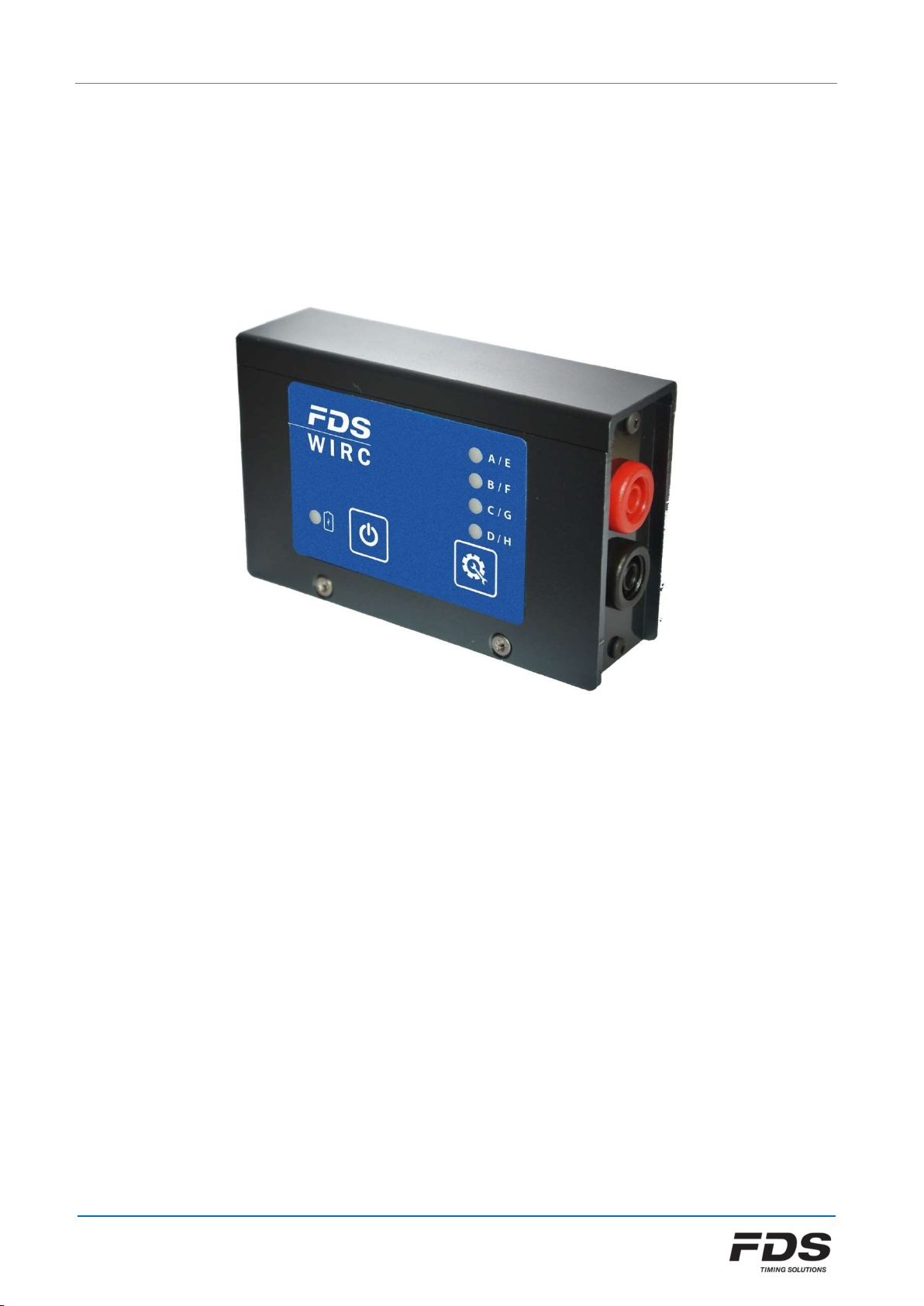
WINP (Wireless Input)
1. Appearance
The transmitter WINP (Wireless Input) will interface most of the existing wired timing devices
(E.g. photocell, start gate) to an FDS wireless setup (TBox-Radio).
WINP – Wireless Input User manual
December 2021 - Version EN 1.3
www.fdstiming.com
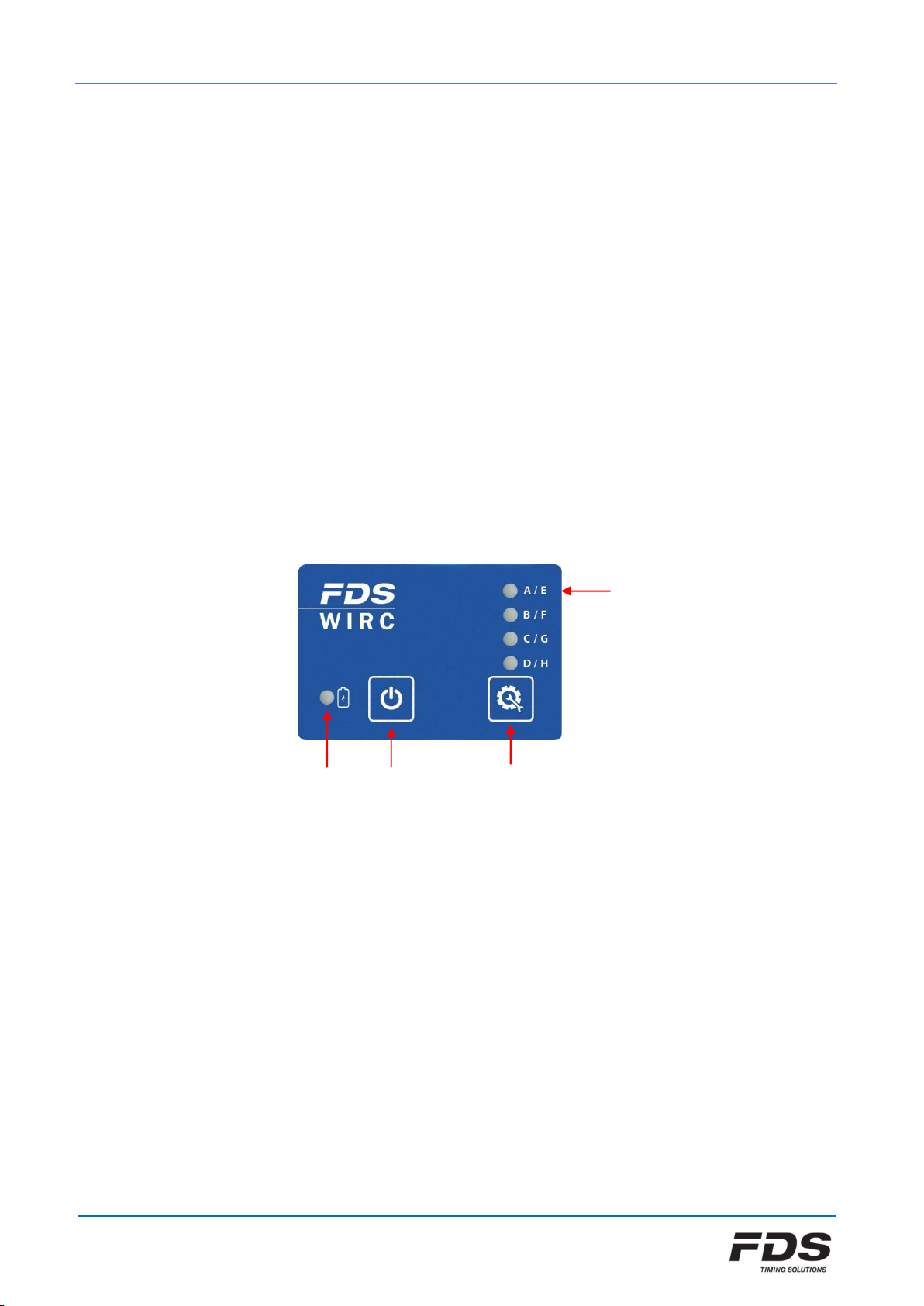
2. Power ON/OFF
The ON/OFF button switch has 2 functions:
1) Battery status
Press and hold the ON/OFF button (front left)
LED green: > 60%
LED yellow: > 30%
LED red: < 30%
2) Switch ON – OFF the WINP
a) Press and hold (1sec. – 2secs.) the ON/OFF button until the battery LED status is Yellow
b) Immediately release the ON/OFF button and quickly repress it (within 1 second) and
hold down until the battery Led status briefly flashes Yellow and then turns to Green.
c) To switch OFF WINP, simply repeat step a and b (until the LED is OFF)
ON/OFF
Button
Status
LED
Setup
Button
LED
Settings

WINP – Wireless Input User manual
December 2021 - Version EN 1.3
www.fdstiming.com
3. Battery status
1) Battery status whilst charging
LED
WINP On/Off USB Battery
Yellow OFF connected Battery Charging
Green OFF connected 100% charged
Yellow Flashing ON connected Battery Charging
Green Flashing ON connected 100% Charged
2) Battery status with device ON and USB disconnected
LED
WINP On/Off USB Battery
Green ON disconnected 60% - 100% charged
Yellow ON disconnected 15% - 60% charged
Red ON disconnected < 15% charged
3) Battery status with device OFF and USB disconnected
Test by briefly pressing ON / OFF button
LED
WINP On/Off USB Battery
Green OFF disconnected 60% - 100% charged
Yellow OFF disconnected 30% - 60% charged
Red OFF disconnected <30% charged
4. Wireless configuration
The transmitter WINP is configured and linked to a TBox-Radio using two Parameters
Group (radio frequency)
Input/ID (TBox Inputs / WINP serial number)
NOTE: TBox-Radio and WINP transmitter must be configured with an identical Group setting

WINP – Wireless Input User manual
December 2021 - Version EN 1.3
www.fdstiming.com
4.1. Groups (radio frequencies) - Europe / India / Russia
6 Groups are available.
Group A, B, C, D:
Wireless Transmission Distance: up to 2000m (clear line of sight)
Each group uses ¼ of the full frequency band
Min locking time of 200ms
Group E, F:
Wireless Transmission Distance: up to 5000m (clear line of sight)
Each group uses the full frequency band
Those groups limit the use of 2 WINP/WIRC only
Min locking time is longer: 500ms
OFF:
The radio transmission function is disabled.
4.2. Groups (radio frequencies) - North America / Japan
8 Groups are available
Group A, B, C, D:
Tested wireless Transmission Distance (clear line of sight)
US : up to 4000m
Japan : up to 1000m
Min locking time of 200ms
Group E, F, G, H:
Tested wireless Transmission Distance (clear line of sight)
US : up to 6000m
Japan : up to 1500m
Those groups limit the use of 2 WINP/WIRC only,
Min locking time is longer: 500ms
OFF:
The radio transmission function is disabled.

WINP – Wireless Input User manual
December 2021 - Version EN 1.3
www.fdstiming.com
To configure your desired Group, press the Setup button
The current Group selected is indicated by the LED array (A, B, C & D)
Release and press the number of times you want to change the setting.
Group LED A LED B LED C LED D
A GREEN
B GREEN GREEN
C GREEN GREEN GREEN
D GREEN GREEN GREEN GREEN
E YELLOW
F YELLOW YELLOW
G (*) YELLOW YELLOW YELLOW
H (*) YELLOW YELLOW YELLOW YELLOW
OFF RED RED RED RED
(*) only available for North America and Japan
4.3. TBox-Radio Input (WINP Pairing)
Each WINP/WIRC has a unique ID (serial number) that can be paired with a TBox-Radio input
(A-D).
Pairing can be performed on a TBox using the “TBox-Setup” application (no need to power
ON WIRC/WINP). Pairing can also be performed manually without any application. In this
case, both TBox-Radio and WINP/WIRC have to be powered and the following procedure
executed.
1) On the TBox-Radio, enter the pairing mode by pressing the Setup button for 3 sec
until a long beep sounds and LED A flash yellow.
2) Select then the desired input (A, B, C or D) by performing short press on the same
button.
3) Finally enter the pairing mode on the WINP/WIRC by pressing the Setup button for
3 second.
When pairing is completed, LEDs A to D of the TBox flash yellow and both TBox and
WINP/WIRC resume normal operation.
To exit manually the pairing mode on either TBox or WINP/WIRC, just press the Setup button
for 3 second until a long beep sound.
NOTE: In case an IOS or PC application is used to configure the radio inputs on a TBox, do
not use the same WIRC/WINP serial number for more than one input.

WINP – Wireless Input User manual
December 2021 - Version EN 1.3
www.fdstiming.com
5. Radio communication
Any messages which did not receive an ACK form the TBox-Radio will be resend several times.
The WIRC/WINP indicates each time an impulse is transmitted or re-transmitted, by flashing its
A/E LED.
Green flash on A/E LED means that pulse transmission is successfully completed.
Yellow flash on A/E LED means the last message did not received any ACK.
Red flash on A/E LED means no that no ACK has been received from the TBox-Radio after all
attempts (impulse might be lost).
The ACK feature provides the user with a basic level of testing the positioning and
communication between TBox-Radio and WIRC/WINP.
Many attempts (yellow or red flashes) may indicate that the communication is not very stable. A
change of position of the WIRC/WINP or the TBox-Radio (maybe just the antennas) may improve
the communication.
Radio transmissions cannot be 100% guaranteed. An unfavourable environment, lack of line
of sight, interference or an improper installation might lead to the loss of data.
FDS cannot be held responsible for any of the above.
6. Wired connection
The jack output (Pin1) is equipped with an optocoupler which support up to 16V.
The signal received on the main input is digitally filtered and transmitted to this output with a
few microseconds delay.
The RS232 input allows communication with other device such as our RCID (RFID-TAG detector)
1: Input
2: NC
3: GND

WINP – Wireless Input User manual
December 2021 - Version EN 1.3
www.fdstiming.com
7. USB
The Mini-USB connector has various functions including:
External power supply and battery charging
Configure the WINP photocell options /parameters
Update the Firmware
Hardware reset in the unlikely event of a frozen WINP
(using the app “WIRC/WINP Setup & Reset”)
8. How to update the WINP firmware
Updating the firmware is relatively simple. The software “FdsFirmwareUpdate” is required
a) Install the program “FdsFirmwareUpdate” on your computer
b) Connect the USB cable to your PC and WINP
c) Run the program “FdsFirmwareUpdate”
d) Select the COM Port
e) Select the update file (.bin)
f) Press Start on the program (do not unplug the device during update)
g) The WINP transmitter will be updated
h) Once the update is complete, remove USB cable and switch ON the WINP transmitter
9. Technical specifications
Frequencies & Power :
Europe
India
Russia
North America
Japan (TBox-41 only)
869.4 - 869.65 MHz 100mW
865 - 867 MHz 100mW
868.7 - 869.2 MHZ 100mW
920 - 924 MHz 100mW
922 - 927 MHz 20mW
Radio impulse precision 1/10’000 sec
Min locking time
(between two detections)
200ms for Groups A-D
500ms for Groups E-H
Operating temperature: -20°C to 60°C
Battery charge possible only between 0°C and 45°C
External power input USB compatible (5V +/- 5%) up to 1A
Battery LiPo 1700mAh
Autonomy @20°C 150 hours radio ON
Dimension 93x58x27mm
Weight 200gr

WINP – Wireless Input User manual
December 2021 - Version EN 1.3
www.fdstiming.com
10. Copyright and Declaration
This manual has been compiled with great care and the information it contains has been
thoroughly verified. The text was correct at the time of printing, however the content can
change without notice. FDS accepts no liability for damage resulting directly or indirectly from
faults, incompleteness or discrepancies between this manual and the product described.
The sale of products, services of goods governed under this publication are covered by FDS’s
standard Terms and Conditions of Sales and this product publication is provided solely for
informational purposes. This publication is to be used for the standard model of the product of
the type given above.
Trademarks: All hardware and software product names used in this document are likely to be
registered trademarks and must be treated accordingly.
FDS-TIMING Sàrl
Rue du Nord 123
2300 La Chaux-De-Fonds
Switzerland
www.fdstiming.com
Table of contents


