WIKA S-20 User manual
Operating instructions
Betriebsanleitung
Mode d'emploi
Manual de instrucciones
GB
D
F
E
Pressure transmitter model S-20
Druckmessumformer Typ S-20
Pressure transmitter model S-20
Transmisor de presión modelo S-20
Transmetteur de pression type S-20

2 WIKA operating instructions pressure transmitter, model S-20
GB
D
14043170.01 04/2013 GB/D/F/E
F
E
Operating instructions model S-20 Page 3 - 24
Betriebsanleitung Typ S-20 Seite 25 - 48
Mode d'emploi type S-20 Page 49 - 70
Manual de instrucciones modelo S-20 Página 71 - 93
© 2013 WIKA Alexander Wiegand SE & Co. KG
All rights reserved. / Alle Rechte vorbehalten.
WIKA® is a registered trademark in various countries.
WIKA® ist eine geschützte Marke in verschiedenen Ländern.
Prior to starting any work, read the operating instructions!
Keep for later use!
Vor Beginn aller Arbeiten Betriebsanleitung lesen!
Zum späteren Gebrauch aufbewahren!
Lire le mode d'emploi avant de commencer toute opération !
A conserver pour une utilisation ultérieure !
¡Leer el manual de instrucciones antes de comenzar cualquier trabajo!
¡Guardar el manual para una eventual consulta!

3WIKA operating instructions pressure transmitter, model S-20
14043170.01 04/2013 GB/D/F/E
GB
Contents
Contents
1. General information 4
2. Safety 6
3. Specications 9
4. Design and function 13
5. Transport, packaging and storage 14
6. Commissioning, operation 15
7. Zero point adjustment 20
8. Maintenance and cleaning 21
9. Faults 22
10. Dismounting, return and disposal 23
Appendix 1: EC Declaration of conformity model S-20 47
Declarations of conformity can be found online at www.wika.com.

4 WIKA operating instructions pressure transmitter, model S-20
14043170.01 04/2013 GB/D/F/E
GB
1. General information
1. General information
■
The pressure transmitter described in the operating instructions has been designed and manufactured using state-
of-the-art technology.
All components are subject to stringent quality and environmental criteria during
production. Our management systems are certied to ISO 9001 and ISO 14001.
■
These operating instructions contain important information on handling the instrument. Working safely requires that
all safety instructions and work instructions are observed.
■
Observe the relevant local accident prevention regulations and general safety regulations for the instrument's range
of use.
■
The operating instructions are part of the product and must be kept in the immediate vicinity of the instrument and
readily accessible to skilled personnel at any time.
■
Skilled personnel must have carefully read and understood the operating instructions prior to beginning any work.
■
The manufacturer's liability is void in the event of any damage caused by using the product contrary to its intended
use, non-compliance with these operating instructions, assignment of insuciently qualied skilled personnel or
unauthorised modications to the instrument.
■
The general terms and conditions contained in the sales documentation shall apply.
■
Subject to technical modications.
■
Further information:
- Internet address: www.wika.de / www.wika.com
- Relevant data sheet: PE 81.61
- Application consultant: Tel.: (+49) 9372/132-8976
Fax: (+49) 9372/132-8008976
E-mail: [email protected]
5WIKA operating instructions pressure transmitter, model S-20
14043170.01 04/2013 GB/D/F/E
GB
Explanation of symbols
WARNING!
... indicates a potentially dangerous situation that can result in serious injury or death, if not avoided.
CAUTION!
... indicates a potentially dangerous situation that can result in light injuries or damage to the equipment or
the environment, if not avoided.
Information
... points out useful tips, recommendations and information for ecient and trouble-free operation.
WARNING!
... indicates a potentially dangerous situation that can result in burns, caused by hot surfaces or liquids, if
not avoided.
Abbreviations
2-wire The two connection lines are used for the voltage supply.
The measurement signal also provides the supply current.
3-wire Two connection lines are used for the power supply.
One connection line is used for the measurement signal.
UBPositive power supply terminal
0V Negative power supply terminal
S+Positive output terminal
1. General information

6 WIKA operating instructions pressure transmitter, model S-20
14043170.01 04/2013 GB/D/F/E
GB
2. Safety
WARNING!
Before installation, commissioning and operation, ensure that the appropriate pressure transmitter has been
selected in terms of measuring range, design and specic measuring conditions.
Non-observance can result in serious injury and/or damage to the equipment.
WARNING!
■
Open the connections only after the system has been depressurised.
■
Observe the working conditions in accordance with chapter 3 "Specications".
Further important safety instructions can be found in the individual chapters of these operating instructions.
2.1 Intended use
The pressure transmitter is used to convert pressure into an electrical signal.
With hydrogen applications, use is only permitted when a medium and ambient temperature of 30 °C
is not exceeded.
For applications with direct contact with foodstus this pressure transmitter is not suitable.
The instrument has been designed and built solely for the intended use described here, and may only be used
accordingly.
The technical specications contained in these operating instructions must be observed. Improper handling or opera-
tion of the pressure transmitter outside of its technical specications requires the instrument to be taken out of service
immediately and inspected by an authorised WIKA service engineer.
The manufacturer shall not be liable for claims of any type based on operation contrary to the intended use.
2. Safety
7WIKA operating instructions pressure transmitter, model S-20
14043170.01 04/2013 GB/D/F/E
GB
2.2 Personnel qualication
WARNING!
Risk of injury should qualication be insucient!
Improper handling can result in considerable injury and damage to equipment.
The activities described in these operating instructions may only be carried out by skilled personnel who
have the qualications described below.
Skilled personnel
Skilled personnel are understood to be personnel who, based on their technical training, knowledge of measurement
and control technology and on their experience and knowledge of country-specic regulations, current standards and
directives, are capable of carrying out the work described and independently recognising potential hazards.
Special operating conditions require further appropriate knowledge, e.g. of aggressive media.
2.3 Special hazards
WARNING!
For hazardous media such as oxygen, acetylene, ammable or toxic gases or liquids, and refrigeration
plants, compressors, etc., in addition to all standard regulations, the appropriate existing codes or
regulations must also be followed.
WARNING!
Residual media in dismounted pressure transmitters can result in a risk to persons, the environment and
equipment.
Take sucient precautionary measures.
2. Safety

8 WIKA operating instructions pressure transmitter, model S-20
14043170.01 04/2013 GB/D/F/E
GB
If the serial number becomes illegible due to mechanical damage or overpainting, traceability will no longer be
possible.
Explanation of symbols
CE, Communauté Européenne
Instruments bearing this mark comply with the relevant European directives.
2. Safety
2.4 Labelling / safety marks
Product label
Model
P# product number
S# serial number
Measuring range
Output signal
Power supply
Pin assignment see explanation of symbols

9WIKA operating instructions pressure transmitter, model S-20
14043170.01 04/2013 GB/D/F/E
GB
3. Specications
3. Specications
Permissible temperature ranges
Medium Ambient Version
-30 ... +100 °C -30 ... +100 °C -
-40 ... +125 °C -40 ... +125 °C -
-40 ... +150 °C -40 ... +125 °C 1) with cooling element
-40 ... +200 °C -40 ... +125 °C 1) with cooling element
-20 ... +60 °C -20 ... +60 °C Oxygen applications
1) Derating curve and formula
Depending on the choice of sealing on the process connection and the electrical connection, there may be limitations
in the medium and the ambient temperatures.
Ambient temperature [°C]
Medium temperature [°C]
Maximum permissible ambient temperature
Tamb (Tmed < 125 °C) = 125 °C
Tamb (Tmed ≥ 125 °C) = -0.62 x Tmed + 202 °C
Tamb = Ambient temperature [°C]
Tmed = Medium temperature [°C]
Maximum permissible medium temperature
Tmed (Tamb < 80 °C) = 200 °C
Tmed (Tamb ≥ 80 °C) = -1.61 x Tamb + 326 °C

10 WIKA operating instructions pressure transmitter, model S-20
14043170.01 04/2013 GB/D/F/E
GB
3. Specications
Electrical connection maximum permissible temperature
Angular connector DIN 175301-803 A -30 ... +100 °C
Angular connector DIN 175301-803 C -30 ... +100 °C
Circular connector M12 x 1 (4-pin) -30 ... +100 °C
Circular connector M12 x 1 (4-pin, metallic) -40 ... +125 °C (cULus: +85 °C)
Bayonet connector (6-pin) -40 ... +125 °C
Field case -25 ... +100 °C
Heavy-duty connector -40 ... +125 °C
Cable outlet IP 67 -30 ... +100 °C
Cable outlet ½ NPT conduit -30 ... +100 °C (cULus: +90 °C)
Cable outlet IP 68 -30 ... +125 °C (cULus: +90 °C)
Cable outlet IP 68, FEP -40 ... +125 °C (cULus: +105 °C)
Cable outlet IP 69K -30 ... +125 °C (cULus: +90 °C)
Climate class
Storage: 1K3 (per EN 60721-3-1)
Transport: 2K2 (per EN 60721-3-2)
Operation: 4K4H (per EN 60721-3-4, without condensation or icing)
Vibration resistance (per IEC 60068-2-6)
20 g, 10 ... 2,000 Hz, (40 g, 10 ... 2,000 Hz for heavy-duty connector)
For instruments with cooling elements a limited vibration resistance applies 10 g (10 ... 2,000 Hz)
Continuous vibration resistance (per IEC 60068-2-6)
10 g
Shock resistance (per IEC 60068-2-27)
100 g, 6 ms (500 g, 1 ms for heavy-duty connector)
Free-fall test (following IEC 60721-3-2)
Individual packaging: 1.5 m
Multiple packaging: 0.5 m
PE bag: 0.5 m

11WIKA operating instructions pressure transmitter, model S-20
14043170.01 04/2013 GB/D/F/E
GB
3. Specications
Vacuum tightness
Yes
Overpressure limit
The overpressure limit is based on the sensor element used. Depending on the selected process connection and
sealing, restrictions in overpressure safety can result. A higher overpressure limit will result in a higher temperature
error.
Measuring range < 10 bar/150 psi ≥ 10 bar/150 psi
3 times (standard) 2 times 1) (standard)
5 times 3 times 2) 3)
1) Restriction: max. 60 bar/870 psi with absolute pressure
2) Only possible for relative pressure measuring ranges ≤ 400 bar or 5,800 psi
3) Only possible for absolute pressure measuring ranges < 16 bar or 220 psi
Process connection Maximum overpressure limit
G ⅛ B 800 bar
G ¼ B, G ¼ B female, G ⅜ B 1,400 bar
G ½ B 1,800 bar (1.4404), 3,200 bar (1.4542)
G ¼ A, G ½ A, M14 x 1.5, M12 x 1.5 600 bar
M20 x 1.5 1,800 bar (1.4404)
3,300 bar (1.4542)
7/16-20 UNF BOSS 600 bar
7/16-20 UNF J514 sealing cone 74° 1,100 bar
9/16-18 UNF BOSS 600 bar
⅛ NPT 1,100 bar
¼ NPT, ¼ NPT female 1,500 bar
½ NPT 1,500 bar (1.4404), 2,800 bar (1.4542)
PT ¼ 1,600 bar
PT ½ 1,500 bar
PT ⅜ 1,400 bar
R ¼ 1,600 bar
R ½ 1,500 bar
R ⅜ 1,400 bar (1.4404), 2,840 bar (1.4542)
All process connections in combination with a cooling element have a maximum overpressure limit of 400 bar.

12 WIKA operating instructions pressure transmitter, model S-20
14043170.01 04/2013 GB/D/F/E
GB
3. Specications
Ingress protection
Electrical connection Ingress protection
Angular connector DIN 175301-803 A IP 65
Angular connector DIN 175301-803 C IP 65
Circular connector M12 x 1 (4-pin) IP 67
Circular connector M12 x 1 (4-pin, metallic) IP 67
Bayonet connector (6-pin) IP 67
Field case IP 6K9K
Heavy-duty connector IP 68
Cable outlet IP 67 IP 67
Cable outlet ½ NPT conduit IP 67
Cable outlet IP 68 IP 68
Cable outlet IP 68, FEP IP 68
Cable outlet IP 6K9K IP 6K9K
Electrical protective measures
The electrical protective measures are not valid for ratiometric output signals.
■
Short-circuit resistance: S+ vs. U-
■
Reverse polarity protection: U+ vs. U-
■
Resistance to overvoltage: DC 40 V (cULus: DC 35 V)
■
Insulation voltage: DC 750 V, not suitable as electric shock protection
CE conformity
■
EMC directive: 2004/108/EC, EN 61326 emission (group 1, class B) and interference immunity
(industrial application)
■
Pressure equipment directive: 97/23/EC
EM eld
30 V/m (80 ... 1,000 MHz)
RoHS conformity
RoHS-compliant

13WIKA operating instructions pressure transmitter, model S-20
14043170.01 04/2013 GB/D/F/E
GB
3. Specications / 4. Design and function
For special model numbers, e.g. S-20000, please note the specications stated on the delivery note.
For further specications see WIKA data sheet PE 81.61 and the order documentation.
4. Design and function
4.1 Description
The prevailing pressure is measured at the sensor element through the deformation of a diaphragm. By supplying
power, this deformation of the diaphragm is converted into an electrical signal. The output signal from the pressure
transmitter is amplied and standardised. The output signal is proportional to the measured pressure.
4.2 Scope of delivery
Cross-check scope of delivery with delivery note.
14 WIKA operating instructions pressure transmitter, model S-20
14043170.01 04/2013 GB/D/F/E
GB
5. Transport, packaging and storage
5.1 Transport
Check the pressure transmitter for any damage that may have been caused during transportation.
Obvious damage must be reported immediately.
5.2 Packaging
Do not remove packaging until just before mounting.
Keep the packaging as it will provide optimum protection during transport (e.g. change in installation site, sending for
repair).
5.3 Storage
Permissible conditions at the place of storage:
■
Storage temperature: -40 ... +70 °C
■
Humidity: 67 % relative humidity (no condensation)
Avoid exposure to the following factors:
■
Direct sunlight or proximity to hot objects
■
Mechanical vibration, mechanical shock (putting it down hard)
■
Soot, vapour, dust and corrosive gases
■
Humid or wet environment
■
Potentially explosive environments, ammable atmospheres
Store the pressure transmitter in its original packaging in a location that fulls the conditions listed above.
WARNING!
Before storing the instrument (following operation), remove any residual media. This is of particular
importance if the medium is hazardous to health, e.g. caustic, toxic, carcinogenic, radioactive, etc.
5. Transport, packaging and storage
15WIKA operating instructions pressure transmitter, model S-20
14043170.01 04/2013 GB/D/F/E
GB
6. Commissioning, operation
6.1 Mechanical mounting
Only use original accessories. For accessories see data sheet PE 81.61.
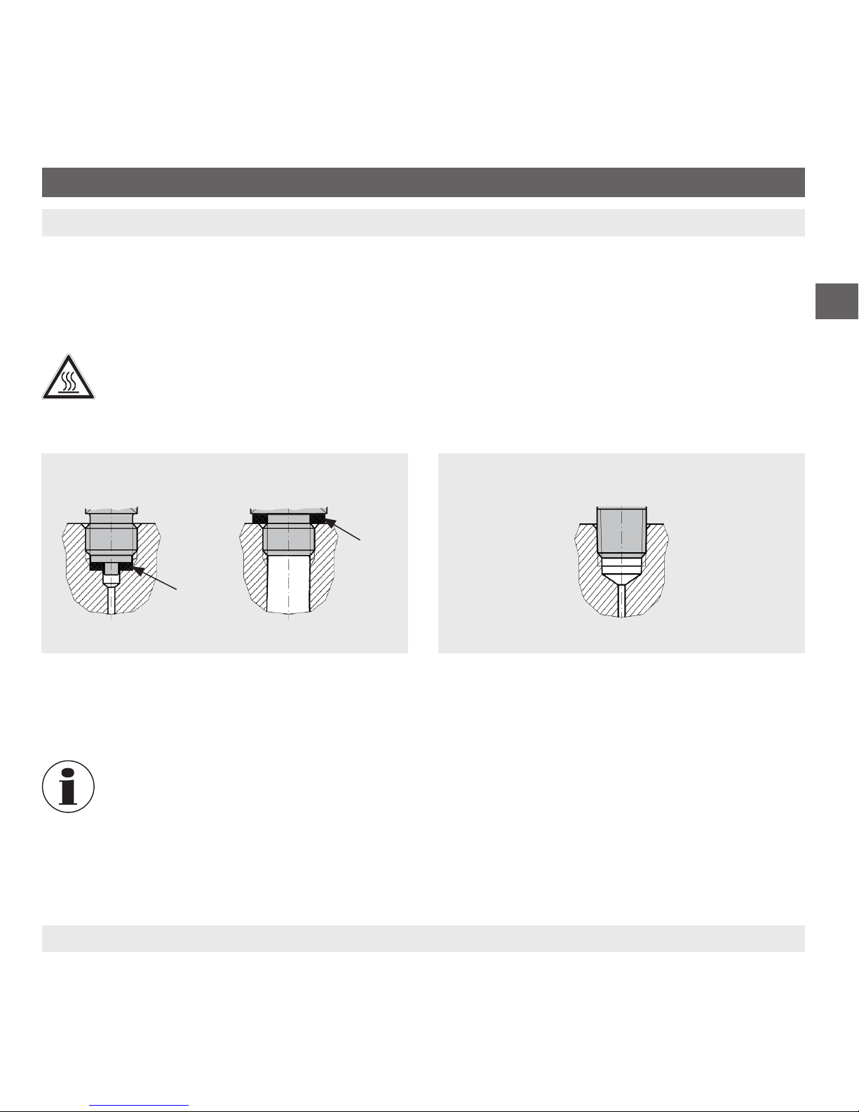
6.1.1 Sealing the process connection
WARNING!
Risk of burns!
The cooling element can be hot as a result of previous use. Allow the cooling element to cool beforehand.
The sealing faces at the instrument have to be undamaged and clean.
6. Commissioning, operation
Correct sealing of the process connections with parallel
threads at the sealing face must be made using suita-
ble at gaskets, sealing rings or WIKA prole sealings.
For sealing process connections with tapered threads,
the sealing must be made in the threads using additional
sealing material, e.g. PTFE tape (EN 837-2).
For further information on seals see WIKA data sheet AC 09.08 or at www.wika.com.
per EN 837 per DIN 3852-E NPT, R and PT
Parallel threads Tapered threads
16 WIKA operating instructions pressure transmitter, model S-20
14043170.01 04/2013 GB/D/F/E
GB
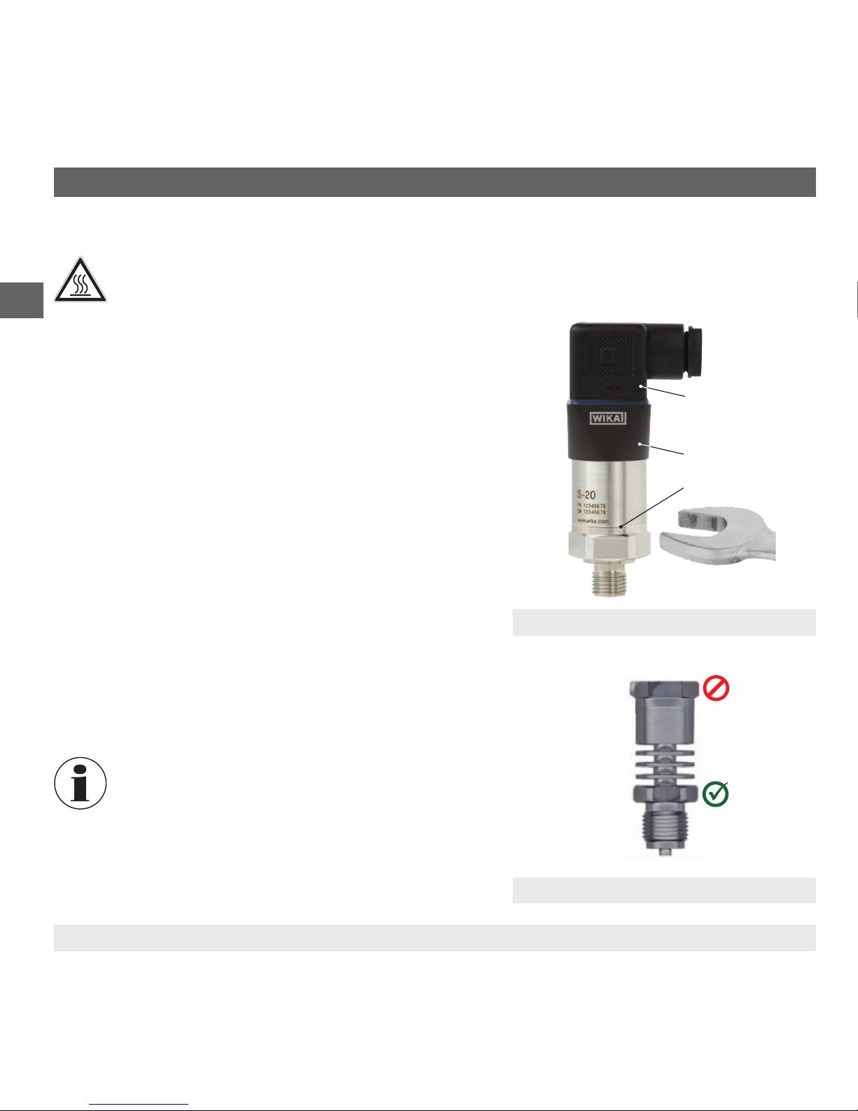
6.1.2 Installing the instrument
WARNING!
Risk of burns!
The cooling element can be hot as a result of previous use. Allow the cooling element to cool beforehand.
■
When screwing the instrument in, the force required to do
this must not be applied through the case or the cap ring, but
only through the spanner ats provided for this purpose and
using a suitable tool.
When there is a cooling element, the lower hexagon should
be used for tightening (see gure a "Mounting cooling
element")
The correct torque depends on the dimensions of the
process connection and the gasket used (form/material).
■
When screwing in, do not cross the threads.
■
For heat dissipation, the cooling element must not be
insulated.
■
If the instrument is mounted upside down, it must be ensured
that no water can collect on the electrical connection and on
the cap ring. Water can block the pressure compensation
diaphragm.
For information on tapped holes and welding sockets,
see Technical information IN 00.14 at www.wika.com.
6. Commissioning, operation
Spanner ats
Cap ring
Model S-20 without cooling element
Mounting a cooling element
Electrical
connection

17WIKA operating instructions pressure transmitter, model S-20
14043170.01 04/2013 GB/D/F/E
GB
6. Commissioning, operation
6.2 Electrical mounting
Only use original accessories. For accessories see data sheet PE 81.61.
WARNING!
The instrument shield does not act as a protective conductor for protection of personnel, rather as a
functional ground in order to shield the instrument from electromagnetic elds.
6.2.1 Connection assembly
■
For instruments with ratiometric output signals, a shielded cable must be used. The cable shield must be grounded,
if the cable is longer than 30 m or leaves the building.
■
Use a cable with suitable characteristics for the particular operating conditions.
■
For cable variants, strain relief must be employed.
■
Cable with ventilation tubes must be vented to atmosphere.
■
The instrument must be earthed via the process connection!
■
Select a cable diameter that matches the cable gland of the plug. Make sure that the cable gland of the mounted
plug has a tight t and that the seals are present and undamaged. Tighten the threaded connection and check that
the seal is correctly seated, in order to ensure a tight seal.
■
For cable outlets, make sure that no moisture enters at the cable end.
Specications for the assembly congurations of the mating connectors
Mating connectors for electrical connection Wire cross-section Cable diameter
Angular connector DIN 175301-803 A max. 1.5 mm26 ... 8 mm
Angular connector DIN 175301-803 C max. 0.75 mm24.5 ... 6 mm
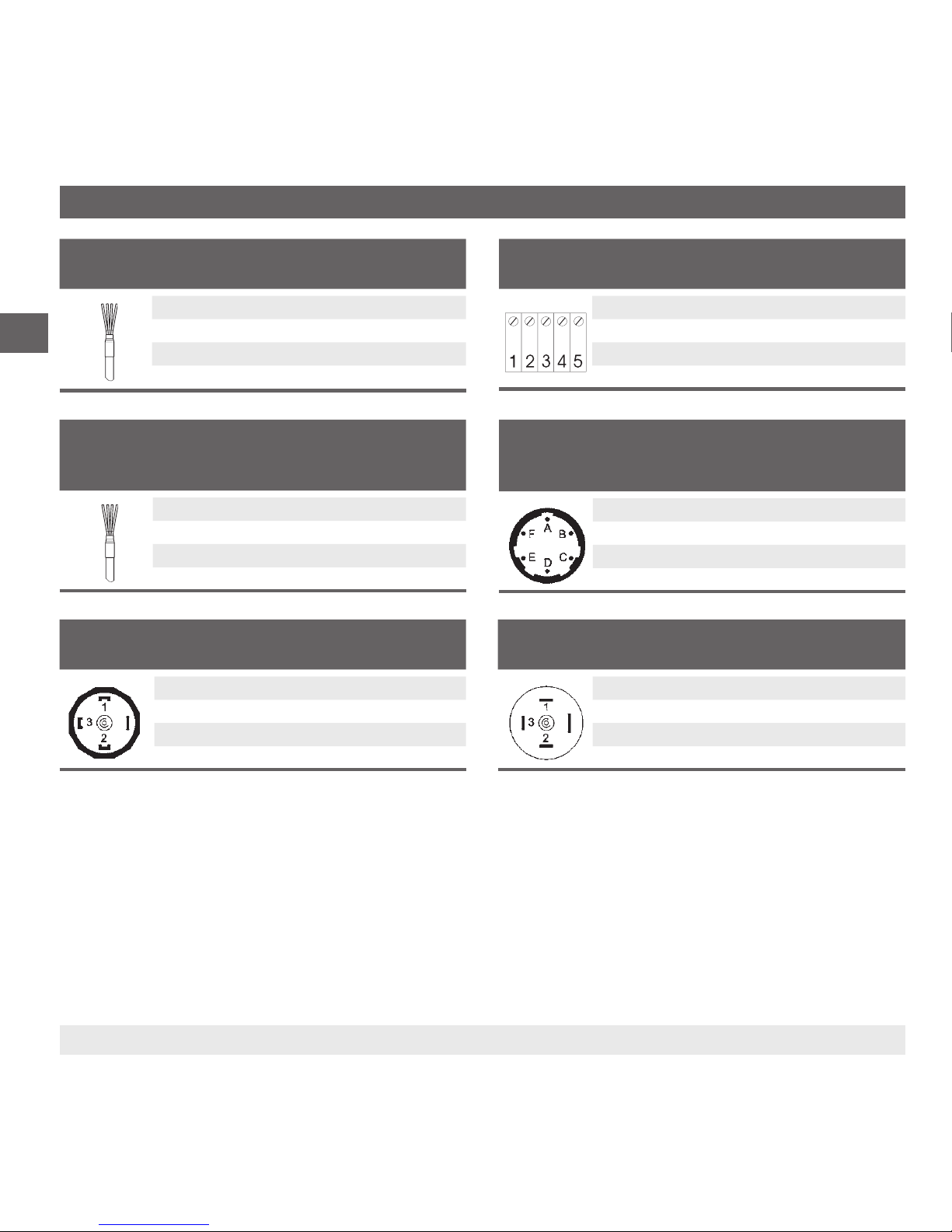
6.2.2 Pin assignment
Heavy-duty connector
2-wire 3-wire
U+1 1
U-2 2
S+- 3
Shield Case Case
Circular connector M12 x 1 (4-pin)
2-wire 3-wire
U+1 1
U-3 3
S+- 4
Shield Case Case
18 WIKA operating instructions pressure transmitter, model S-20
14043170.01 04/2013 GB/D/F/E
GB
6. Commissioning, operation
6.2.3 Setting up a voltage supply
The voltage supply is made via a power supply unit or a control unit which provides the energy limitation.
The power supply for the pressure transmitter must be made via an energy-limited electrical circuit in accordance with
section 9.3 of UL/EN/IEC 61010-1, or an LPS to UL/EN/IEC 60950-1, or class 2 in accordance with UL1310/UL1585
(NEC or CEC). The power supply must be suitable for operation above 2,000 m should the pressure transmitter be
used at this altitude.
Angular connector DIN 175301-803 A
2-wire 3-wire
U+1 1
U-2 2
S+- 3
Shield 4 4
Angular connector DIN 175301-803 C
2-wire 3-wire
U+1 1
U-2 2
S+- 3
Shield 4 4
Bayonet connector (6-pin)
2-wire 3-wire
U+A A
U-B B
S+- C
Shield Case Case
Field case
2-wire 3-wire
U+1 1
U-2 2
S+- 3
Shield 5 5
Cable outlet incl. mating connector with moulded
cable
2-wire 3-wire
U+brown (BN) brown (BN)
U-blue (BU) blue (BU)
S+- black (BK)
Shield grey (GY) grey (GY)
Cable outlet (US code)
2-wire 3-wire
U+red (RD) red (RD)
U-
black (BK)
black (BK)
S+- white (WH)
Shield grey (GY) grey (GY)

19WIKA operating instructions pressure transmitter, model S-20
14043170.01 04/2013 GB/D/F/E
GB
6. Commissioning, operation
The permissible power supply depends on the corresponding output signal.
With cULus approval: max. DC 35 V (DC 32 V with heavy-duty connector)
Output signal Power supply
4 ... 20 mA DC 8 ... 36 V (DC 12 ... 36 V with optional settling time of 1 ms)
20 ... 4 mA DC 8 ... 36 V
DC 0 ... 10 V DC 12 ... 36 V
DC 0 ... 5 V DC 8 ... 36 V
DC 1 ... 5 V DC 8 ... 36 V
DC 0.5 ... 4.5 V DC 8 ... 36 V
DC 1 ... 6 V DC 9 ... 36 V
DC 10 ... 0 V DC 12 ... 36 V
DC 0.5 ... 4.5 V DC 5 V ±10 %
Output signal Load in Ω
Current output ≤ (power supply - 7.5 V) / 0.023 A
≤ (power supply - 11.5 V) / 0.023 A (with optional settling time of 1 ms)
Voltage output > maximum output voltage / 1 mA
Ratiometric output > 4.5 kΩ
Dissipation loss
■
Current output: 828 mW (22 mW/K derating of the dissipation loss with ambient temperatures ≥ 100 °C)
■
Voltage output: 432 mW
Current supply
■
Current output: Current signal, max. 25 mA
■
Voltage output: max. 12 mA

20 WIKA operating instructions pressure transmitter, model S-20
14043170.01 04/2013 GB/D/F/E
GB
7. Zero point adjustment
7. Zero point adjustment
1
2
120° → ±0,05%
max. ±10%
±0,05%
±0,05%
±0,05%
–
+
3
4
1 2
3 4
Other manuals for S-20
1
Table of contents
Languages:
Other WIKA Transmitter manuals


