EMP Tek VT-40.2 User manual

INTEGRATED HYBRID TUBE AMPLIFIER
Model VT-40.2
HYBRID TUBE AMPLIFIER
OW N ER’S M A N UA L

Safety Instructions
e lightning ash with the arrowhead symbol within an equilateral triangle is
intended to alert the user to the presence of un-insulated “dangerous voltage”
within the product enclosure that may be of sucient magnitude to constitute a
risk of shock to persons.
The exclamation point within an equilateral triangle is intended to alert the user
to the presence of important operating and maintenance (servicing) instructions
in the literature accompanying the product.
When using your amplier basic safety precautions should always be followed to reduce
the risk of re, electric shock, and injury.
1. Do not open the amplier, attempt any modications or repairs. ere are extremely
high voltages present and any servicing must be referred to EMP Tek or an authorized
qualied technician.
2. Opening the amplier will void the warranty.
3. To prevent shock or re hazard, never permit moisture or any liquid to get into the
amplier. If an accidental spill occurs, immediately shut o the power, unplug its
AC power cord and seek a qualied technician for repair.
4. To reduce the risk of electric shock, do not remove the cover (or back). No user
serviceable parts inside of amplier.
5. All safety instructions should be read before this amplier is operated. Please retain
these safety instructions for future reference. All warnings on the amplier and in
this manual should be adhered to.
6. e amplier should be placed so its location or position provides proper ventilation
on all sides of the amplier on a solid surface.
6. e amplier should only be connected to a power supply type described in this
manual or as marked on the amplier.
7. Power supply cords should be routed so they will not be pinched or walked on.
8. e amplier should never be exposed to any liquids of any kind or objects lled
with liquids (vases or plants).
1
Introduction
Congratulations on your purchase of the EMP Tek VT-40.2 integrated hybrid tube
amplier! Your amplier is the result of many years of research and development.
is manual contains setup recommendations and specications for the amplier. It
is highly recommended you thoroughly read through the material contained in this
manual before connecting your amplier. is will ensure you have an understanding of
how to properly setup, operate and maintain your amplier for optimum performance
and maximum enjoyment.
2
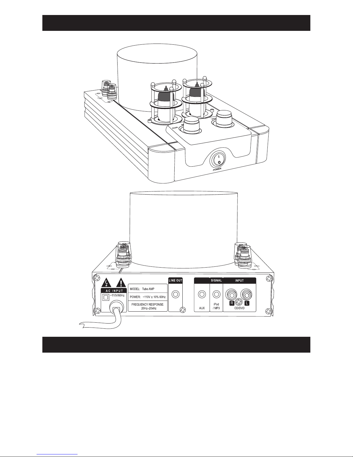
VT-40.2 Integrated Tube Amplier
Front View
Back View
Maintenance and Cleaning
To maintain the amplier's appearance, it is recommended use of a dry or slightly-
damp so cloth to keep the exterior of the amplier free from dust, lint or dirt. When
cleaning the amplier, make sure the amplier is turned o.
WARNING: DO NOT apply a damp cloth to the vacuum tubes when they are warm
or hot. Damage to the vacuum tubes will result.

Vacuum Tubes
Most of the maintenance on your amplier will involve the vacuum tubes. e tubes
used in the VT40.2 are type 6N3. e tubes have a lifespan up to approximately 5 years
of outstanding performance depending on usage. Tube wear is gradual and usually goes
unnoticed until new replacements are installed. Worn tubes tend to sound at with
reduced punch, clarity and high end. Symptoms of failing vacuum tubes may include:
• Any intermittent noise
• Excessive hum
• Excessive white noise
• Inability to get a clean sound
• Loss of power
If the outer plates of a tube begin to glow brightly, this tube has shorted. Turn o the
amplier and replace the tubes, preferably with a matched set. It is okay in an emergency
to replace only one tube, but both tubes should be replaced with a matched set. ese
tubes have been tested and matched according to their power and performance
characteristics. A matched set of power tubes will signicantly lower audible hum and
increase power output and clarity in sound.
Replace Tubes By:
1. Turn o power at switch.
2. Unplug amplier from the power source.
3. Using a glove or clean dry cloth, carefully remove the tubes
from their sockets by pulling them straight up.
4. Insert a new set of tubes using a glove or dry cloth.
NOTE: New tubes can be purchased from EMP Tek at www.emptek.com
3
Features
• Classic tube pre-amplier design principals reduce odd-order harmonic distortion.
• Tubes provide a “sweet” pure and accurate sound.
• Connections for Subwoofer, iPod/MP3, CD/DVD and an additional Auxiliary component.
• 40 Watts per channel output easily drives most speakers.
• High quality machined aluminum case looks beautiful and aids in heat dissipation.
• Blue highlighted vacuum tubes in stylish protective cages for added visual elegance.
• High quality binding posts for secure connections of up to 12-gauge wire.
• Hand-painted and polished beautiful front accent panel.
• Power supply housing machined of solid aluminum, black anodized.
• Stable rubber feet add style and vibration damping.

Choose a location where air can circulate freely around the amplier. Do not cover
the amplier.
Amplier Location
4
Attaching Speaker Wires
When using a banana jack to attach speaker wires to the binding post terminals, loosen
the top as shown in step 1, and then insert the speaker wire into the banana jack as
shown in step 2. Next insert the banana jack into the binding posts on the amplier
into the hole provided in the top of the terminal, and then tighten down the screw as
shown in step 3 until secure. Repeat for the other speaker wire(s) as necessary.
If not using a banana jack, simply loosen the binding nut to allow the hole in the side
of the terminal to become exposed as shown in step 1. Strip ¼-inch of the insulation
from the end of the speaker wire and insert the exposed wire end into the now exposed
hole in the side of the terminal as shown in step 2. Tighten the binding nut by turning
the nut clockwise until the speaker wire is secured as shown in step 3. Repeat for the
other speaker wire(s) as necessary.

TOP VIEW
FRONT SIDE VIEW
FRONT AND TOP PANELS
Power: e power on/o switch is located on the front face of the amplier.
Volume: e volume can be adjusted using the knob on the top of the amplier. Make
sure the volume is set at a low setting when initially setting up the amplier.
Mode: Using the Mode knob on the top of the amplier you can select from either
AUX, MP3 or CD/DVD inputs.
Le Speaker Connection: Connection for the le speaker
Right Speaker Connection: Connection for the right speaker
Using the Amplier
5
6
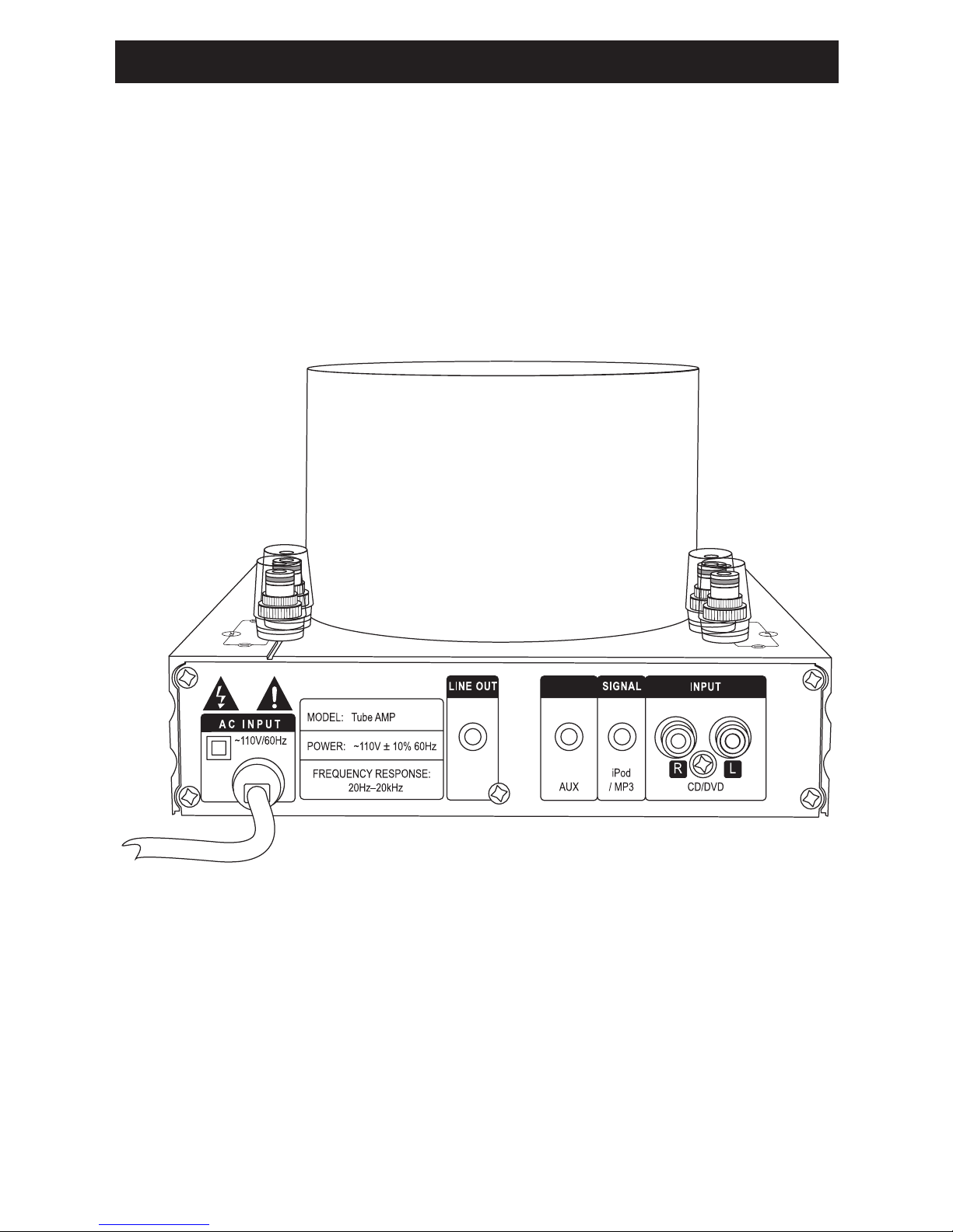
BACK VIEW
Using the Amplier (continued)
BACK PANEL
Variable Line Out: Headphones or to another amplier or powered subwoofer
AUX: Stereo input for any device with line out
iPod/MP3: Stereo input for an iPod or MP3 player
Input: Stereo input for a CD/DVD or any device with a low-level stereo line out

Specications
*iPod is a registered trademark of Apple Inc.
7
Model
Amplier Type:
AC Input:
Power Output:
Frequency Response:
Distortion (THD):
S/N Ratio
Pass Band:
Signal Input (Analog):
Line Level Input Sensitivity:
Dimensions:
Weight:
Warranty:
VT-40.2
Integrated Tube Hybrid
110V±10%/60Hz
40 Watts Per Channel @ 8 Ohms
60 Watts Per Channel @ 4 Ohms
20Hz–20kHz
<2%
>80dB
10Hz–100kHz
– AUX (1/8-inch jack)
– iPod*/MP3 (1/8-inch jack)
– R/L (CD/DVD) (RCA jacks)
450mV
6-5/8" W x 4-1/2" H x 10-1/4" D
(168mm W x 114mm H x 260mm D)
8 lbs. (3.63 Kg)
1 Year

Troubleshooting
e following chart should help isolate some common problems you may encounter
with your amplier. Some are obvious problems you can remedy, but remember,
THERE ARE NO USER SERVICEABLE PARTS INSIDE THE AMPLIFIER. If you
cannot identify the cause of the problem using the chart, and are in need of repair,
return the amplier to an EMP Tek authorized service facility.
8
Situation
Amplier does not
come on when power
switch is on.
No sound coming from
speakers, no audible hum
from amplier.
Amplier channels shut
down while the amplier
is powered on.
Distorted sound.
Probable Cause
Power is not connected.
No source voltage.
Speaker output wire not
connected.
Volume control is turned
to the lowest setting.
Blown fuse
Amplier is overheating,
protection circuit has
engaged to avoid damage
to the amplier.
Worn tubes
Solution
Ensure power cord is
plugged in.
Verify power source with
something you know
works.
Check all input and
output connections are
secure.
Increase volume control.
Ensure the tubes are
properly seated in their
sockets.
Ensure power cord is
seated securely.
Contact Emp Tek
customer support (www.
support@emptek.com)
for instructions on how
to replace the fuse.
Turn amplier o for at
least 20 minutes, circuit
will reset aer cool down.
Replace tubes (6N3)

Warranty
Engineered Music Products “EMP Tek” warrants the VT-40.2 integrated tube ampli-
er (the "Product") to be free from original manufacturing defects in materials and
workmanship for one (1) year from date of purchase from an authorized EMP Tek
reseller. is warranty extends only to the original consumer purchaser. EMP Tek does
not warrant goods used in industrial applications. is warranty does not cover any
expenses incurred in any removal or re-installation of the product.
If the product should prove defective within the warranty period, contact EMP Tek
for a return authorization number prior to returning the product by prepaid delivery
to EMP Tek, along with the original sales invoice or other proof of purchase, which
establishes eligibility for warranty service. EMP Tek will, at its option, replace or repair
the product free of charge and return the product by prepaid delivery. is warranty
does not apply to any product which has been damaged, misused, altered, neglected or
repaired by anyone other than an EMP Tek authorized service facility.
Any implied warranties including tness for use and merchantability are limited in
duration to the period of the express warranties set forth above, and no person is
authorized to assume for EMP Tek any other liability in connection with the sale of
the product. EMP Tek expressly disclaims liability for any incidental and consequential
damages caused by the product or the result of failure of this product. e remedies
provided under this warranty are exclusive and in lieu of all others.
is warranty gives specic legal rights. In addition, there may be other legal rights
arising from the sale of the product, which vary from state to state. Some states do not
allow the exclusion or limitation of incidental or consequential damages, so the above
limitation or exclusion may not apply in some areas.
Extended warranty available at www.emptek.com/extendwarranty.php
9


382 Marshall Way, Layton, Utah • USA • 84041
Toll Free: (801) 991-1308 • Fax: (801) 543-3300
www.emptek.com
It is EMP Tek policy to continuously incorporate improvements into products; all specications are subject to change without notice.
Copyright © 2010 EMP Tek. All Rights Reserved.
Table of contents


