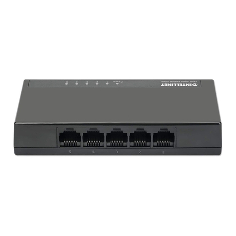
EMS5 EMS5-8MA User manual

EMS5-8MA-SWITCH
8 port 10/100/1000 Gigabit
Green Network
Managed Switch
User’s Guide

I
COPYRIGHT
All
rights
reserved.
No
part
of
this
publication
may
be
reproduced,
stored
in
a
retrieval
system,
or
transmitted
in
any
form
or
by
any
means,
whether
electronic,
mechanical,
photo
copying, recording
or
otherwise,
without
the
prior
written
permission
of
the
publisher.
FCC WARNING
This
equipment
has
been
tested
and
found
to
comply
with
the
limits
for
a
class
B
device, pursuant
to
part
15
of
FCC
rules.
These
limits
are
designed
to
provide
reasonable
protection against
harmful
interference
in
a
commercial
installation.
This
equipment
generates,
uses
and can
radiate
radio
frequency
energy
and,
if
not
installed
and
used
in
accordance
with
the instructions,
may
cause
harmful
interference
to
radio
communication.
Operation
of
this equipment
in
a
residential
area
is
likely
to
cause
harmful
interference,
in
which
case,
the
user will
be
required
to
correct
the
interference
at
the
user’s
own
expense.
CE
This
is
a
Class
B
product.
In
a
domestic
environment,
this
product
may
cause
radio
interference
in
which
case
the
user
may
be
required
to
take
adequate
measures.
Take
special
care
to
read
and
understand
all
the
content
in
the
warning
boxes:
Warning

II
TABLE OF CONTENTS
FCC WARNING...........................................................................I
1.INTRODUCTION .......................................................................................................................................... 1
2.Key Features.................................................................................................................................................1
3.Getting Started ..............................................................................................................................................2
3.1 Connect To EMS5-8MA-SWITCH Web pages..............................................................................2
3.2 Menu Description...............................................................................................................................3
3.3 Switch Panel Description .................................................................................................................4
4. Function Description ...................................................................................................................................4
4.1 System ................................................................................................................................................4
4.1.1 Information ..............................................................................................................................4
4.1.2 IP Setting.................................................................................................................................4
4.1.3 User Account...........................................................................................................................6
4.1.4 Port Setting .............................................................................................................................6
4.2 Configuration...................................................................................................................................... 7
4.2.1 VLAN........................................................................................................................................ 7
4.2.1.1 Static VLAN..................................................................................................................7
4.2.1.2 VLAN Setting...............................................................................................................8
4.2.1.3 Admin VLAN(option)...................................................................................................9
4.2.2 QOS........................................................................................................................................10
4.2.2.1 Port-based Priority.................................................................................................10
4.2.2.1 Queue Weight.......................................................................................................... 10
4.2.3 Service VLAN ....................................................................................................................... 11
4.2.3.1 TPID setting.............................................................................................................. 11
4.2.3.2 Uplink Port Setting.................................................................................................12
4.2.3.3 Static Service VLAN...............................................................................................12
4.2.4 IGMP......................................................................................................................................13
4.2.5 Trunk Group Setting.............................................................................................................14
4.2.6 Loop Prevention...................................................................................................................15
4.2.7 Port-based Mirroring............................................................................................................ 16
4.2.8 Port Isolation......................................................................................................................... 17
4.2.9 Bandwidth Control................................................................................................................18
4.2.10 Jumbo Frame .....................................................................................................................19
4.2.11 MAC Constraint..................................................................................................................20
4.2.12 Green Ethernet................................................................................................................... 21
4.2.13 EEE......................................................................................................................................22
4.2.14 SNMP...................................................................................................................................23
4.2.15 Provision(option)................................................................................................................23
4.3 Security.............................................................................................................................................24
4.3.1 MAC Address........................................................................................................................24

III
4.3.1.1 MAC Search .............................................................................................................24
4.3.1.2 Static MAC................................................................................................................25
4.3.2 Storm Control........................................................................................................................ 26
4.4 Monitoring......................................................................................................................................... 27
4.4.1 Port Statistics........................................................................................................................27
4.4.2 Cable Diagnostic.................................................................................................................. 28
4.5 Tools ..................................................................................................................................................29
4.5.1 Firmware Upgrade...............................................................................................................29
4.5.2 Configuration Backup..........................................................................................................29
4.5.3 Reset......................................................................................................................................30
4.5.4 Save.......................................................................................................................................30
4.5.5 Reboot ................................................................................................................................... 30
5. Contact Information
.................................................................................................................................. 38

1
1.INTRODUCTION
This Layer 2 Gigabit Managed Switch is a perfect solution for young and dynamic Offices with small
network user groups. bridge that efficiently extends 10/100/1000 Ethernet circuits to user side Networking,
LAN side for Internet and Intranet access. The document is user guide for EMS5-8MA-SWITCH Green
Network Managed Switch. The EMS5-8MA-SWITCH acts as a web server to accept http connection request
and replies web pages so that user can get configuration or change configuration to EMS5-8MA-SWITCH by
web access.
2.Key Features
8 LAN gigabit non-blocking Managed switch.
Each port supports full duplex 10/100/1000M connectivity (half duplex only supported in 10/100 mode)
Full-duplex and half-duplex operation with IEEE 802.3x flow control and backpressure.
Support 9K bytes jumbo packet length forwarding at wire speed.
Support RJ45 Cable Test Function.
Support IEEE 802.1Q VLAN.
Support Loop Prevention configuration.
Support Quality of Service (QoS).
Support RFC MIB Counter.
Support Stacking VLAN and Port Isolation.
Support IEEE 802.1ad Stacking VLAN.
Support IEEE 802.3ad Link aggregation port group.
Broadcast/Multicast/Unknown Uni/Multicast storm control protects system from attack by hackers.
Support Green Ethernet features.(Link-On Cable Length Power Saving, Link-Down Power Saving)
Support EEE 802.3az

2
3.Getting Started
3.1 Connect To EMS5-8MA-SWITCH Web pages
Connect the EMS5-8MA-SWITCH through http service, Typping the IP in the URL of browser. We suggest
using Mozilla Firefox(3.6 above) , Firefox to access the web of EMS5-8MA-SWITCH. In the first, the
default IP is static IP setting.
192.168.172.2 and the net-mask is 255.255.255.0. Please configure the IP and net-mask of your host
correctly to access the EMS5-8MA-SWITCH web pages.
If you connect to EMS5-8MA-SWITCH successfully, you will see an authentication dialog. Please enter
“admin” @ username and “12345” at password to login.
Figure: 3.1
After you login in the web page successfully, you will see the Product information page. This page show
some information of this EMS5-8MA-SWITCH device. The upper frame is the front panel frame, which

3
shows the connection situation of each port. If a port is linked up, the corresponding port on the front panel
will be green, such as LAN2 port on Figure 3.1
3.2 Menu Description
The left panel shows the configuration that user can access through web pages. Some configuration web
pages are hidden by the group label. To expand the group label, click the plus sign on the left side of group
label.
Figure: 3.2

4
3.3 Switch Panel Description
The top panel shows the Switch connect status for operator can access through web pages and know the
Switch status.
Panel had three type define,
3.3.1 “Green.” mean normal connector
3.3.2 ”Black” mean disconnect
3.3.3 “Yellow” mean Loop port Provision block port
Figure: 3.3
4. Function Description
User can configure EMS5-8MA-SWITCH through web pages, such as VLAN entry, IP setting. In this section,
configuration that user can access through web pages will be introduced.
4.1 System
4.1.1 Information
This page shows the EMS5-8MA-SWITCH configuration such as Ethernet Address, IP address and firmware
version.
Figure: 4.1.1
4.1.2 IP Setting
This page shows IP configuration. User can set static IP address, or enable DHCP client function to get IP.

5
Figure: 4.1.2
Note:
a.)The Default IPAddress Setting is Static IP setting.

6
4.1.3 User Account
This page shows username and password configuration. User can change username and password in this
page.
Figure: 4.1.3
Note:
a.)The Default Login User: admin
b.)The Default Password : 12345
4.1.4 Port Setting
This page shows link status, speed, duplex, and flow control ability of all ports. User can change port ability
of switch in this page.
Figure: 4.1.4

7
4.2 Configuration
4.2.1 VLAN
4.2.1.1 Static VLAN
This page shows information of static VLAN entries. User can add/remove static VLAN entries in this page.
Figure: 4.2.1
Parameter
Description
Member
The Port is a member of the specified VLAN and the frames of this VLAN can
be switched through this port, but the tagging information in the frame header
is not modified by the Switch.
Untagged
The port is an untagged port (as defined in 802.1Q) that is participating in the
VLAN. In such an untagged port the Switch will strip off the 802.1Q tag from
the incoming and outgoing frames if they are tagged in such a way. This is
used for sending frames to non-802.1Q-compliant devices.
Tagged
The port is a tagged port (as defined in 802.1Q) andis participating in the
VLAN. The Switch will put the VLAN information of the port –including VID
and Priority –into the header of the untagged frames coming in or transmitted
from the port. The tagged VLAN information in the frames can later be used
by other 802.1Q-compliant devices for forwarding decisions.
Not Member
The port is not participating in the VLAN as identified by the selected VID(VLAN ID).
Note:
a.) Default VLAN with VIS being “1” cann’t be removed.

8
4.2.1.2 VLAN Setting
This page shows VLAN port information. User can assign PVID, tag egress mode, accepted frame type of
each port.
Figure: 4.2.2
Parameter
Description
PVID
Default PVID=1, User can assign new PVID for setting.
Set the VLAN ID. The limit is 1 to 4095. The VLAN ID is assigned to all
untagged frames received on this port.
Mode
(Tag Egress mode)
Tag Egress mode, accepted frame type of each port.
Original: - Output frame will follow VLAN untag setting.
Keep-format: - Output frame will keep original(VLAN or Un-Tag) format.
Priority-tag: - Output frame will be priority tag(Output frame is tagged with
VID=0).

9
4.2.1.3 Admin VLAN(option)
This page showsAdministrator VLAN for CPU port. User can assign PVID, tag, accepted
management frame to CPU port.
Figure: 4.2.3
Note:
a.) Enable Admin VLAN will be apply to SNMP, Web, and ping etc. service.

10
4.2.2 QOS
4.2.2.1 Port-based Priority
This page shows port-based priority of each port. User can configure port priority with 4 priority level
of each port.
Figure: 4.2.4
4.2.2.1 Queue Weight
This page shows the priority to queue mapping. User can set the sixteen priority to queue mapping
of each priority.
Figure: 4.2.5

11
4.2.3 Service VLAN
4.2.3.1 TPID setting
Tag protocol identifier (TPID). With the IEEE standard 802.1ad, double-tagging can be useful for
Internet service providers, allowing them to use VLANs internally while mixing traffic from clients that
are already VLAN-tagged. The outer (next to source MAC and representing ISP VLAN) S-VLAN Tag
(service VLAN tag) comes first, followed by the inner C-VLAN Tag (customer tag). In such cases,
802.1ad specifies a TPID of 0x88a8 for service-provider outer S-VLAN Tag.
Figure: 4.2.6
The device determines whether a received frame carries a service provider VLAN tag (S-VLAN Tag)
or a customer VLAN tag (C-VLAN Tag) by checking the TPID value. After receiving a frame, the
device compares the configured TPID value with the value of the TPID field in the frame. If the two
match, the frame carries the corresponding VLAN tag.
Figure: 4.2.7

12
4.2.3.2 Uplink Port Setting
This page shows the device uplink port setting for handling Q-in-Q tag. User can set which port is
working for uplink port function.
Figure: 4.2.8
4.2.3.3 Static Service VLAN
This page shows information of Service VLAN entries. User can add/remove Service VLAN entries
in this page.
Figure: 4.2.9

13
4.2.4 IGMP
The IGMP menu is used for configuring IGMP snooping. IGMP means "Internet Group Management
Protocol". It is a protocol through which hosts can register with their local router for multicast services. If
there is more than one multicast router on a given sub- network, one of the routers is elected and assumes
the responsibility of keeping track of group membership.
Figure: 4.2.10

14
4.2.5 Trunk Group Setting
Port Trunking defines anetwork link aggregation and trunking method which specifies how to create a
single high-speed logical link that combines several physical links. Use the Trunk Configuration page shown
above to create trunk groups. The Switch supports amaximum of one trunk groups for 1000Mbps ports.
Each trunk group in groups may be comprised of up to four ports, selected from any combination of
1000Mbps ports.
Figure: 4.2.11

15
4.2.6 Loop Prevention
The EMS5-8MA-SWITCH supports loop prevention function that can detect and relieve a loop situation of
Ethernet network topology. As long as loop condition is detected, the switch blocks the port automatically and
starts to blink the port Link/Act LED to indicate which port has been blocked to relieve a loop. When a loop
condition disappears, the port Link/Act LED returns to normal port property state automatically.
Figure: 4.2.12

16
4.2.7 Port-based Mirroring
Set the port mirroring option to monitor data being transmitted through a specific port.
Figure: 4.2.13
Note:
Parameter
Description
Mirror Direction
Select appropriate mode
Disable: –Mirror mode is disabled
RX: –Monitor only incoming traffic
TX: –Monitor only outgoing traffic
Both: –Monitor both incoming and outgoing traffic
Mirroring Port
Select the port which will do the monitoring.
Mirrored Port List
Select the port that needs to be monitored.
Table of contents
Popular Switch manuals by other brands
Matrix Switch Corporation
Matrix Switch Corporation MSC-XV1616L product manual
SMC Networks
SMC Networks IS1000 Series quick start guide
Philips
Philips UID8460/10 installation instructions
Dell
Dell Wyse R Class manual
CTS
CTS FOS-3124-BAT-II Series user guide
Ihse
Ihse Draco tera enterprise 480 Series Quick setup
