EMTOP SBC930 User manual
SBC930
Evaluation Board
User Manual
Version 0.0 – Oct.21, 2019


Embedded Solutions Specialist
Website:www.emtop-tech.com Product Wiki: www.emtop-tech.com/wiki
Table of Contents
CHAPTER 1 PRODUCT OVERVIEW.......................................................................................... 1
1.1 INTRODUCTION.................................................................................................................... 1
1.2 RESOURCES DOWNLOAD...................................................................................................1
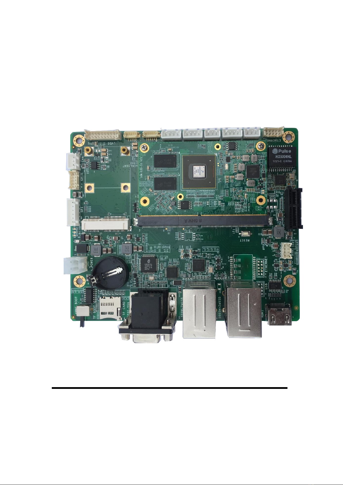
1.3 HARDWARE OVERVIEW.......................................................................................................2
1.2.1 SOM-930-33............................................................................................. 2
1.2.2 Extension Board.......................................................................................3
CHAPTER 2 HARDWARE SYSTEM............................................................................................5
2.1 CORE BOARD......................................................................................................................5
2.2 INTRODUCTION TO PERIPHERALS.......................................................................................5
2.3 HARDWARE INTERFACES.................................................................................................... 7
CHAPTER 3 DETAIL OF INTERFACE........................................................................................ 9
3.1 Connector of LVDS interface J7............................................................ 9
3.2 Backlight connector J5..........................................................................12
3.3 Touch interface J6..................................................................................14
3.4 USB For Touch CON2...........................................................................16
3.5 RS232 connector CON6.......................................................................18
3.6 RS232 connector CON4.......................................................................20
3.7 UART connector CON5........................................................................ 22
3.8 Fan connector CON11.......................................................................... 24
3.9 Reset key S2.......................................................................................... 26
3.10 10/100/1000M ethernet connector J21(not install default)............. 27
3.11 PCIe Connector CON8......................................................................... 30
3.12 Optional USB connector J19............................................................... 32
3.13 HDMI connector J17............................................................................. 34
3.14 USB Double and 10/100/1000Mbps Ethernet Connector J2......... 35
3.15 Internal USB connector J18.................................................................37

Embedded Solutions Specialist
Website:www.emtop-tech.com Product Wiki: www.emtop-tech.com/wiki
3.16 Internal 10/100/1000Mbps Ethernet connector J20........................ 39
3.17 USB Double and 10/100mbps connector J8.....................................42
3.18 DB9 and VGA double connector J11..................................................43
3.19 TF Connector CON1............................................................................. 45
3.20 Boot Select Switch S1...........................................................................46
3.21 Power Connector J1..............................................................................48
3.22 SPI Connector CON10......................................................................... 50
3.23 GPIO Connector J12.............................................................................52
3.24 CAN Connector CON7..........................................................................54
3.25 CR2032 Battery Connector JP10....................................................... 56
3.26 mSATA Connector CN1........................................................................ 57
3.27 PCI connector JP1.................................................................................59
CHAPTER 4 QUICK START........................................................................................................61
4.1 FUSE SYSTEM IMAGE INTO MICROSD CARD..................................................................61
4.2 BOOT FROM MICROSD CARD......................................................................................... 63
4.3 FUSE EMMC IMAGE.........................................................................................................65
4.4 BOOT FROM EMMC......................................................................................................... 66
4.5 BOOT LOGO.................................................................................................................... 66
4.5.1 Replace U-BOOT LOGO......................................................................66
4.5.2 Replace Linux LOGO............................................................................66
4.6 SET DISPLAY DEVICE.......................................................................................................67
CHAPTER 5 FUNCITON TEST................................................................................................... 68
5.1 LED TEST......................................................................................................................... 68
5.2 RTC TEST.........................................................................................................................68
5.3 EEPROM TEST................................................................................................................69
5.4 EMMC TEST..................................................................................................................... 70
5.5 LVDS TEST.......................................................................................................................70
5.6 LVDS BACKLIGHT TEST................................................................................................... 70
Embedded Solutions Specialist
Website:www.emtop-tech.com Product Wiki: www.emtop-tech.com/wiki
5.7 CAPACITIVE TOUCHSCREEN TEST....................................................................................70
5.8 VGA TEST.........................................................................................................................70
5.9 HDMI TEST.......................................................................................................................71
5.10 UART TEST...................................................................................................................... 71
5.11 NETWORK TEST................................................................................................................ 71
5.12 PCIETEST........................................................................................................................ 72
5.13 CANBUS TEST................................................................................................................. 73
5.14 USB HOST TEST.............................................................................................................. 73
5.15 SATA TEST....................................................................................................................... 74
CHAPTER 6 SYSTEM BUILDING.............................................................................................. 75
6.1 SETUP BUILDING ENVIRONMENT..................................................................................... 75
6.2 BUILD U-BOOT................................................................................................................. 75
6.2.1 Build U-Boot for MicroSD Boot............................................................75
6.2.2 Build U-Boot for eMMC Boot............................................................... 76
6.2.3 Update U-Boot Image........................................................................... 76
6.3 BUILD KERNEL..................................................................................................................76
TECHNICAL SUPPORT AND WARRANTY.............................................................................78

Embedded Solutions Specialist
Website:www.emtop-tech.com Product Wiki: www.emtop-tech.com/wiki
Chapter 1 Product Overview
1.1 Introduction
For a small form-factor 82*50mm, the core board SOM-930-33 is a small form-factor that
based on NXP’s iMX6Q/D series SOC. The core board integrates 4*256Mbyte DDR3
SDRAM and a 4~32GB eMMC, employ a 314 Pins gold finger mouth to spread out rich
interfaces from the SOC.
The base board named SBC930 which is design as an expansion board to carry the
SOM-930-33. The flexible design allows the fast and easy way of realizing and upgrading
the core baord’s capabilities. In additional to those features offered by SOM-930-33, the
SBC8600B features 3 serial ports (including 2 RS232 and 1 TTL), 6 USB Host, 3 Ethernet
ports, 1xCAN, VGA, HDMI Out, 1 channel LVDS Out, Touch screen, and more other
peripherals.
1.2 Resources Download
You can access to our remote server to download the hardware and software resources
through 2 ways below:
①Open web browser (Firefox is recommended), input the following url:
http://svn.emtop-tech.com/svn/svnrepos/SBC930/
If the browser reports a warning like " Potential Security Risk Ahead ", please choose the
Advanced.. option and "Accept the Risk and Continue".
Access Authorization:
User Name : SBC930
Password : Please contact with sales@emtop-tech.com
Embedded Solutions Specialist
Website:www.emtop-tech.com Product Wiki: www.emtop-tech.com/wiki
②Run svn command under Linux operating system, such as Debian and Ubuntu:
svn co svn://47.113.100.69/SBC930
Note:
If the command not found, please install svn tools : apt-get update && apt-get install -y
subversion
The svn program will ask for access authorization:
User Name : SBC930
Password : Please contact with sales@emtop-tech.com
1.3 Hardware Overview
The following sections list out all the hardware features of the two parts of SBC930
respectively.
1.2.1 SOM-930-33
Electric Features
Working Temperature: 0 °C~ 70°C for commercial, -45 °C~70 °C for
inductrial with cool system
Working Humidity: 20% ~ 90%, Non-Condensing
Dimesions: 82mm x 50mm
Input Voltage: 4.2V
Processor
1GHz ARM Cortex™-A9 64-Bit RISC Microprocessor with TrustZone
NEON MPE coprocessor
32KB/32KB of L1 Instruction/Data Cache with Single-Error Detection
(parity)
1MB of L2 Cache with Error Correcting Code (ECC)
Memories

Embedded Solutions Specialist
Website:www.emtop-tech.com Product Wiki: www.emtop-tech.com/wiki
4GB ~ 32GB eMMC
4*256MB DDR3 SDRAM
Expansion Interfaces and Signals Routed to Pins
314 Pins gold finger mouth
A TFT LCD Interface (Support LCDs with 24-bpp parallel RGB interface)
One USB2.0 High-Speed Host and one USB OTG Interfaces
For UART Interfaces
A SPI Interface
One 10/100 /1000Mb/s Ethernet
A I2S interface
Three IIC Signals
One 4-line SD/MMC card interfaces
One 8 bits MMC interface
One MIPI camera interface
One parallel camera interface
One HDMI output interface
Two channel LVDS interface
One two line PCIe interface
One SATA interface
1.2.2 Extension Board
Electric Features
Working Temperature: 0 °C~ 70°C
Working Humidity: 20% ~ 90%, Non-Condensing
Dimesions: 150m x 125m
Input Voltage: 12V/2A
Audio/Video Interfaces
Single channel LVDS output support up to 1366*768@60Hz
Embedded Solutions Specialist
Website:www.emtop-tech.com Product Wiki: www.emtop-tech.com/wiki
1x HDMI output support up to 1920*1080@60Hz
1x VGA output
Data Transfer Interface
1x 10/100/1000Mbps Ethernet Interface , which is limited to 470Mbps due to
internal bus throughput limitations of CPU
1x CAN Interface ( FlexCAN)
1x USB 2.0 High-Speed OTG Ports with Integrated PHY (480Mbps, Mini
USB Interface)
6x USB 2.0 High-Speed HOST Ports with Integrated PHY (480Mbps,USB-A
Interfaces)
1x USB 2.0 Host Ports for touch screen
1x I2C tuch screen interface
1x TF Slot (SD/MMC compatible, 3.3V logic level)
Serial Interfaces
UART0, 3-Line RS232 Level, DB9 Debugging Serial Interface
UART2, 3-Line RS232 Level, DB9 General-Purpose Serial Interface
UART3, 3-Line TTL Level, DIP Interface
8x GPIO Interfaces
1x mSATA interface
1x PCIe interface
1x Backlight output
Input Interfaces and others
A Reset Button

Embedded Solutions Specialist
Website:www.emtop-tech.com Product Wiki: www.emtop-tech.com/wiki
Chapter 2 Hardware System
2.1 Core Board
2.1.1 Instroduction to Core Board
SOM-930-33 is a high performances core board base on iMX6 with 314 pins gold finger.
Measuring only 82 x 50mm, the small form-factor core board integrates all the requirements
for driving the iMX6DQ, such as 1GB DDR4, eMMC and power management. These make
the designer simplify to design their product, save time for their development cycle.
SOM-930-33 core board is design to used in medical equipment, industrial control, locomotive
control, data center and so on. SOM-930-33 include 2 USB2.0 high speed interface(1 USB
OTG and 1 USB Host)、2 SDIO、10 bit parallel Camera interface、MIPI 2Lanes Camera
interface、1 GBE、1 I2S、1 SATA high speed interface、2 SPI interface、1 PCIe high speed
interface、4 UART interface、2 CAN MAC、1 HDMI 1.4a output、2 channel LVDS output、24Bits
LCD Parallel output、2 I2C interface、1 SPDIF interface(no driver)and 12 GPIOs.
2.2 Introduction to Peripherals
2.2.1 7 port USB HUB FE2.1
The FE2.1 is a highly integrated, high quality, high performance, low power consumption,
yet low overall cost solution for USB 2.0 High Speed 7-Port Hub. It adopts Multiple
Transaction Translator (MTT) architecture to explore the maximum possible throughput.
Six, instead of two, non-periodic transaction buffers are used to minimize potential traffic
jamming. The whole design is based on state-machine-control to reduce the response
delay time; no micro controller is used in this chip.
2.2.2 USB to Ethernet LAN9500
The LAN950x is a high performances solution for USB to 10/100 Ethernet port bridging.
With applications ranging from embedded systems, set-top boxes, and PVRs, to USB port

Embedded Solutions Specialist
Website:www.emtop-tech.com Product Wiki: www.emtop-tech.com/wiki
replicators, USB to Ethernet dongles, and test instrumentation, the device is targeted as a
high performance, low cost USB/Ethernet connectivity solution.
The LAN950x contains an integrated 10/100 Ethernet PHY, USB PHY, Hi-Speed USB 2.0
device controller, 10/100 Ethernet MAC, TAP controller, EEPROM controller, and a FIFO
controller with a total of 30 KB of internal packet buffering. Two KB of buffer memory are
allocated to the Transaction Layer Interface (TLI), while 28 KB are allocated to the
FIFO Controller (FCT).
2.2.3 RS232 Transceivers SP3232
The SP3222E/3232E series is an RS-232 transceiver solution intended for portable or
handheld applications such as notebook or palmtop computers. The SP3222E/3232E
series has a high-efficiency, charge-pump power supply that requires only 0.1µF
capacitors in 3.3V operation. This charge pump allows the SP3222E/3232E series to
deliver true RS-232 performance from a single power supply ranging from +3.3V to +5.0V.
The SP3222E/3232E are 2-driver/2-receiver devices. This series is ideal for portable or
hand-held applications such as notebook or palmtop computers. The ESD tolerance of the
SP3222E/3232E devices are over ±15kV for both Human Body Model and IEC1000-4-2
Air discharge test methods. The SP3222E device has a low-power shutdown mode where
the devices' driver outputs and charge pumps are disabled. During shutdown, the supply
current falls to less than 1µA.
2.2.4 RGB to VGA Convertor CH7026B-TF
The CH7025/CH7026 is a device targeting handheld and similar consumer systems which
accept digital input signal. CH7025/CH7026 encodes and transmits data through 10-bit
DACs. The device is able to encode the video signals and generate synchronization
signals SDTV format for NTSC and PAL standards and HDTV format for 480p,576p,720p
and 1080i. Analog RGB output and composite SYNC signal are also supported. The
device accepts different data formats including RGB and YCbCr (e.g. RGB565, RGB666,
RGB888, ITU656 like YCbCr, etc.). Both interlaced and noninterlaced input data formats


Embedded Solutions Specialist
Website:www.emtop-tech.com Product Wiki: www.emtop-tech.com/wiki
3)20Pin 2.00mm LVDS Connector mark Pin 1 with triangle, pin sequence is as follow
J7
Pin
Name
Level
CPU
BALL
Default
State
Input/Output
Note
1
PWR_LVDS
Default 3.3V output
2
PWR_LVDS
3
GND
4
GND
5
LVDS0_TX0_N
U2
Output
6
LVDS0_TX0_P
U1
Output
7
GND
8
LVDS0_TX1_N
U4
Output
9
LVDS0_TX1_P
U3
Output

Embedded Solutions Specialist
Website:www.emtop-tech.com Product Wiki: www.emtop-tech.com/wiki
10
GND
11
LVDS0_TX2_N
V2
Output
12
LVDS0_TX2_P
V1
Output
13
GND
14
LVDS0_CLK_N
V4
Output
15
LVDS0_CLK_P
V3
Output
16
GND
17
LVDS0_TX3_N
W2
Output
18
LVDS0_TX3_P
W1
Output
19
BIT_SEL
Output
Optional output pull
up to LVDS_PWR or
pull down, Default
pull down
20
BIT_SEL
0V
Output
Optional output pull
up to LVDS_PWR or
pull down, Default
pull down
4)The specifications for 20Pin 2.00mm LVDS connector are as follows:


Embedded Solutions Specialist
Website:www.emtop-tech.com Product Wiki: www.emtop-tech.com/wiki
3)5Pin Wafer Connector mark Pin 1 with triangle, pin sequence is as follow:
J5
Pin
Name
Level
CPU
BALL
Default
State
Input/Output
Note
1
12V OUT
12V Output
2
GND
3
BKL_EN
3.3V
M23
PU(100K)
Input
4
BKL_PWM
3.3V
T4
PU(100K)
Input
5
NC
4)5Pin 1.25mm WaferThe specifications for are as follows:


Embedded Solutions Specialist
Website:www.emtop-tech.com Product Wiki: www.emtop-tech.com/wiki
3)6Pin wafer connector mark Pin 1 with triangle, pin sequence is as follow:
J6
Pin
Name
Level
CPU
BALL
Default
State
Input/Output
Note
1
3.3V OUT
3.3V output
2
I2C0_SCL
3.3V
N5
PU(100K)
Input
3
I2C0_SDA
3.3V
N6
PU(100K)
Input
4
CTP_INT
3.3V
F14
PU(100K)
Input
5
GND
6
CTP_RST
3.3V
E14
PU(100K)
Input
Table of contents


