ENDEVCO 7310A User manual

IM7310A Rev A
April 7th, 2020
7310A
Angular Rate Sensor
IM7310A
Instruction manual

IM7310A Rev A 2
April 7th, 2020
SAFETY CONSIDERATIONS
Model 7310A Angular Rate Sensor Is declared to fully comply with EU Council Directives:
LowVoltage Directive, 2014/35/EU - Compliant
EMC Directive, 2014/30/EU - Compliant
RoHS Directive, 2011/65/EU and2015/863(RoHS3)- Compliant
The Product listed above is manufactured byEndevco, Inc. and is declared to comply with the noted Product Safety and
Environmental Standards when installed and operated in accordance with the Manufacturer’s instructions provided.
The product is declared to comply by design, testing and 3rd party evaluation (when necessary). The certification
program management, product safety testing, EMC testing and evaluations were provided by Endevco, Inc. or an
Outsourced 3rd Party Provider. RoHS compliance declared by evaluation of product and materials used and exemptions
granted to test instruments. The product is eligible to bear and display the CE mark. All safety and EMC standards
listed beloware the latest revision in force at the time and date tests and evaluations were conducted.
EMC standards
EN 55011, Class A conducted and radiated RF emissions
EN 61000-3-2 Harmonic currentemissions EN 61000-3-3 Voltage fluctuations and flicker
EN 61000-4-2 Electrostatic discharge immunity EN 61000-4-3 Radiated electromagnetic field immunity
EN 61000-4-4 Fast transient burst immunity EN 61000-4-6 Conducted RF immunity
EN 61000-4-11 Voltage dips, short interrupts and variations
Safetystandard
EN/IEC 61010-1; Safety requirements for electrical equipment for measurement, control, and laboratory use - Part 1
This manual contains information and warnings that must be followed to ensure safety of personnel and the safe
operation of the product.
Warnings:
Switch off all power to equipment before connecting or disconnecting the product. Failure to do so may cause
damage to the product.
Any adjustment, maintenance or repair, other than detailed within this manual, must be carried out by trained service
personnel.
If it is suspected that the correct operation of the equipment is threatened, impaired or otherwise, it must be made
safe and free from further operation until the threat has been removed.
To return unwanted product for disposal, please contact your local Endevco representative.

IM7310A Rev A 3
April 7th, 2020
1.0 Table of Contents
1.0 Table of Contents..........................................................................................................................................................................3
2.0 Product Description ......................................................................................................................................................................4
3.0 Materials Required .......................................................................................................................................................................4
4.0 Pre-installation Check-up..............................................................................................................................................................4
5.0 Mounting ......................................................................................................................................................................................4
5.1. Mounting Surface.....................................................................................................................................................................5
5.2. Screw Mount ............................................................................................................................................................................5
5.3. Adhesive Mount .......................................................................................................................................................................6
5.4. Cable.........................................................................................................................................................................................6
5.5. Electrical Connection................................................................................................................................................................6
5.6. Triaxial Mount ..........................................................................................................................................................................6
5.7. 6DoF Mount..............................................................................................................................................................................7
6.0 Electrical Precautions....................................................................................................................................................................8
6.1. Excitation Voltage.....................................................................................................................................................................8
6.2. Signal Leads ..............................................................................................................................................................................8
6.3. Grounding.................................................................................................................................................................................8
6.4. Signal Conditioning...................................................................................................................................................................8
7.0 Recalibration.................................................................................................................................................................................9
8.0 Questions......................................................................................................................................................................................9

IM7310A Rev A 4
April 7th, 2020
2.0 Product Description
The ENDEVCO Model 7310A is an angular rate sensor that utilizes unique silicon MEMS gyroscope technologies with custom
electronics and packaging and provides reliable sensing performance even under excessive shock and vibration
environments. This angular rate sensor is designed specifically for automotive safety testing and other system designs
requiring accurate measurement of angular velocity. As is the practice with all instrumentation, certain electrical
precautions should be followed with pre-installation check-up, mounting and recalibration.
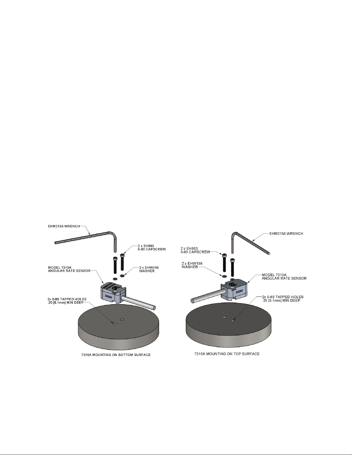
3.0 Materials Required
All the materials used in the mounting of the Model 7310A angular rate sensor are supplied with the unit in the shipping
container. These materials, as shown in Figure 1, include:
(1) Allen wrench for 0-80 screws- Endevco P/N EHM2156 (1pc)
(2) 0-80 x 3/8 inch Socket Head Cap Screws- Endevco P/N EH863 (2pc)
(3) Size 0, Flat Washers- Endevco P/N EHW196 (2pc)
For triaxial angular rate measurements, or Six Degrees of Freedom (6DoF) measurements, the user should consider the
Model 7930 Triax & Six Degrees of Freedom Mounting Block which is available as an optional accessory.
4.0 Pre-installation Check-up
Before installation of the angular rate sensor, it should be checked to insure proper operation. A simple Output Voltage
test can be conducted with minimal test equipment. Place the unit on the flat surface of a vibration-free table top, apply
the specified excitation voltage to the angular rate sensor (see data sheet for proper wiring hook-up) and measure the
output with a voltage meter. Allow the unit to warm-up for one minute before the output voltage measurement.
The output voltage should be measured on the three tests listed in Table 1. The voltage of +OUT(Green) and –OUT(WHITE)
with respect to GND(Black) should fall in range of +2.3V ~ +2.6V, and the voltage of +OUT(Green) with respect to –
OUT(White) should be within -100mV ~ +100mV.
Table 1. Output Voltae test for sensor check-out
If this initial check does not give a proper reading, which indicates a possible malfunction, and the reason for the erroneous
reading cannot be found, please contact mailto:sales@endevco.com for troubleshooting or return.
5.0 Mounting
When mounting the Model 7310A angular rate sensor, it is best to utilize the proper techniques and tools listed to ensure
optimum performance. For triaxial angular rate measurements and 6DoF measurements, the Model 7930 Triaxial
Mounting Block is available - see paragraph 5.6 and 5.7 below.
Connection
Voltage
+OUT(Green) with respect to GND(Black)
+2.3V ~ +2.6V
-OUT(White) with respect to GND(Black)
+2.3V ~ +2.6V
+OUT(Green) with respect to –OUT(White)
-100mV ~ +100mV
IM7310A Rev A 5
April 7th, 2020
5.1. Mounting Surface
The mounting surface should be clean and free of burrs. Two #0-80 tapped holes, 0.2 inch minimum depth should be
spaced 0.3 inches (7.62 mm) apart. A 32 micro inch rms surface finish with flatness of 0.0001 inches is
recommended for the area that will contact the angular rate sensor. The rotational axis of the unit is perpendicular
to the mounting surface, so the angular alignment of the two mounting holes is not critical. The location of the
mounting holes is not critical either, the angular rate sensor can be mounted at the center or close to the edge of the
mounting surface of the rotational substrate.
5.2. Screw Mount
To screw mount Model 7310A to mounting surface, use the supplied mounting washers (EHX196, 18-8 CRES),
mounting screws (EH863, 0-80 x 3/8’’, alloy steel, black oxide finish) and Allen wrench (EHM2156, alloy steel, black
oxide finish) as shown in Figure 1.
Remove the unit from the shipping container. Place the unit on the mounting surface and align the mounting holes.
Slide the washers over the screws. Using the supplied wrench or a torque wrench, tighten the screws to 4 lbf-in (0.45
Nm). This is roughly equivalent to finger tight with the supplied wrench.
The Model 7310A angular rate sensor can be mounted on either the bottom surface of the sensor, as shown in Figure
1(a), or the top surface of the sensor, as shown in Figure 1(b). The rotation arrow mark printed on the top and
bottom surface of the angular rate sensor indicates the positive rotation direction. When mounted on bottom
surface, the angular rate sensor outputs a positive voltage in response to a clockwise rotation. When mounted on
top surface, the angular rate sensor outputs a positive voltage to an anti-clockwise rotation.
FIGURE 1 (Left) Screw Mount of Model 7310A Angular Rate Sensor (on sensor bottom)
(Right) Screw Mount of Model 7310A Angular Rate Sensor (on sensor top)

IM7310A Rev A 6
April 7th, 2020
5.3. Adhesive Mount
Model 7310A angular rate sensor can be mounted by adhesives too. Adhesion of epoxies to the hard anodized case is
excellent, but thermal mismatch to the mounting surface can degrade the joint and cause undulating surface. A
compliant adhesive, such as Dow Corning 3145 RTV, is recommended. Use care to maintain flatness of the unit
during curing to reduce angular rate measurement errors. To remove adhesive-mount sensor from the mounting
surface, apply acetone or other dissolving agent to the adhesive layer using a cotton tip, wait for epoxy to be partly
dissolved before gently removing the sensor by hand or tools. Do not apply excessive strain on the sensor body
during removal of the sensor, especially when the sensor is mounted on the top surface.
5.4. Cable
As practical, tie down the cable within 2 to 3 inches (4 to 6 cm) of the unit. Whipping of the cable during rotation,
vibration and shock will strain the cable unnecessarily at the unit. The cable jacket is silicone, so care should be taken
to avoid cutting or tearing the jacket. The cable is rated for 257°F (125°C) continuous service.
5.5. Electrical Connection
Connect the unit to the signal conditioner using the following lead designation:
Red - Excitation +
Green - Output +
White - Output -
Black - Ground (Excitation -)
Endevco Model 136 3-channel signal conditioner is an optional accessory and is recommended to be used with
Model 7310A.
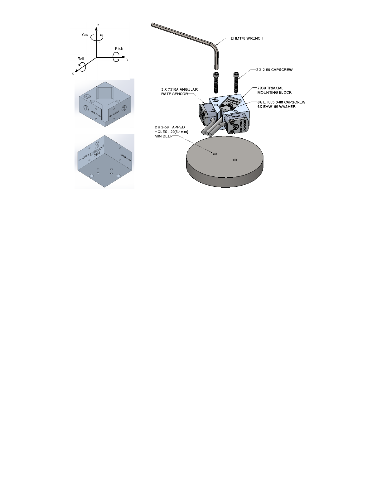
5.6. Triaxial Mount
For triaxial angular rate measurements, the Model 7930 Triax & Six Degrees of Freedom Mounting Block is attached
to the mounting surface with two 2-56 x 5/8 inch socket head cap screws as shown in Figure 2, with subsequent
attachment of the 3pc Model 7310A angular rate sensors per steps 5.2 through 5.5 above. To achieve optimum
mechanical coupling and accurate measurement of angular velocity, the three 7310A units should be mounted to the
three primary mounting surfaces marked of the 7930 block, corresponding to the three perpendicular axes of
rotation (Yaw, Pitch and Roll, top left of Figure 2). Same as the single unit installation in step 5.2, in triaxial
installation the 3pc 7310A units can be mounted on either the top or the bottom surface of the sensor depending on
the positive direction of rotation in the specific application. The Allen wrench (EHM178, alloy steel, black oxide finish)
and the 2pc 2-56 socket cap screws (EH572, 2-25 x 5/8’’, CRES) are supplied as mounting accessories in the shipping
container of the 7930 mounting block.
IM7310A Rev A 7
April 7th, 2020
FIGURE 2. (Top Left) Three Axes of Rotation. (Bottom Left) 7930 Triax & 6DoF Mounting Block
(Right) Installation of 3pc Model 7310A Angular Rate Sensor onto
Model 7930 Triax & 6 Degrees of Freedom Mounting Block
5.7. 6DoF Mount
The Model 7930 mounting block features Six Degree-of-Freedom (6DoF) measurement capability consisting of three
axes of linear acceleration and three axes of angular velocity. 6DoF measurement is important in applications such as
automotive safety testing, aerospace testing and other testing in harsh shock and vibration environments requiring
accurate measurement of a combination of linear and angular motions. For 6DoF measurement, 3pc Model 7310A
angular rate sensors and 3pc 7264 accelerometers are installed to the 7930 mounting block with 0-80 socket head
screws and washers per steps 5.2 to 5.5, as shown in Figure 3. Same as the triaxial installation in step 5.6, the three
angular rate sensors should be installed to the three primary mounting surfaces marked of the 7930 mounting
block, and they can be mounted on either the top or the bottom surface of the sensor depending on the positive
direction of rotation in the specific application. The three accelerometers are installed on the other three surfaces of
the mounting block, measuring linear accelerations along X/Y/Z axis as in the top left figure of Figure 2. The 7930
mounting block is installed to the mounting structure on surface of the block with two 2-56 x 5/8 inch socket head
cap screws. Please ensure the two 0-80 screws for mounting the angular rate sensor in slot of surface of the block
are tightened properly and they do not interfere with the mounting structure surface when the mounting block is
installed to the mounting structure. The EHM178 wrench and 2pc 2-56 socket cap screws are supplied as mounting
accessories in the shipping container of the 7930 mounting block.
Model 7930 mounting block is made of hard anodized aluminum. Drawings and 3D model of the 7930 mounting
block are available per request.

IM7310A Rev A 8
April 7th, 2020
FIGURE 3. (Left) Installation of 3pc Model 7310A Angular Rate Sensor and 3pc Model 7264
Accelerometer onto Model 7930 Triax & 6DoF Mounting Block
(Right) Bottom View of the 6DoF Installation
6.0 Electrical Precautions
6.1. Excitation Voltage
The Model 7310A angular rate sensor has an internal voltage regulator, so excitation from +5Vdc to +16Vdc is
adequate. A low noise power supply is recommended and care should be taken to minimize pickup on the cabling to
the accelerometer. The maximum current drain over the entire operating range is 6 mA. It’s recommended to use
Endevco Model 136 3-channel signal conditioner to provide power and signal processing functions to Model 7310A
angular rate sensor and Model 7264 accelerometer.
6.2. Signal Leads
The green and white signal leads are differential. The green lead has a varying output, while the white lead is fixed at
a reference voltage of approximately +2.5 Vdc. Although the output is high level, at ±2 Vdc, the usual precautions of
using twisted pair, shielded instrumentation cable should be taken to avoid noise pickup on the signal leads.
6.3. Grounding
The case of the model 7310A angular rate sensor is not attached to circuit ground, and the cable shield is not
attached to the case or to circuit ground. The recommended grounding scheme is to ground the cable shield at the
power supply ground and to no other point to avoid ground loops.
6.4. Signal Conditioning
The model 7310A angular rate sensor has a high level differential output of ±2 Vdc, biased at +2.5 Volts. The zero
rotation reading, or Zero Measurand Output (ZMO), is 0 volts ± 100 mV. When the angular rate sensor is subjected
to angular rate greater than the full range, the output of the unit will electrically clip, with a recovery time of < 10
µseconds.

IM7310A Rev A 9
April 7th, 2020
7.0 Recalibration
Sensitivity and Zero Measurand Output calibration should be performed at 6 to 12 month intervals, depending on usage.
Ordinarily, recalibration need be performed only at 12 month intervals if it is known that the angular rate sensor has not been
used beyond its rated specifications. If the unit is used under severe environments, it may be desirable to use shorter
calibration intervals.
Contact Endevco for local calibration facility information or return the 7310A unit to Endevco for recalibration. Endevco
maintains an angular rate recalibration service with A2LA traceability in the United States.
Dirty units may be wiped clean using a damp cloth and a solvent such as acetone.
8.0 Questions
If you have any questions regarding the use of this or any Endevco sensors, please contact mailto:sales@endevco.com or
go to our website https://endevco.com/ for information of Endevco Application Engineering in North America and your
local sales representatives.
Table of contents
Popular Accessories manuals by other brands

MK Electric
MK Electric K4019 Installation and commissioning instructions

Digi
Digi XBee Smart Plug Hardware setup guide

Sandstrom
Sandstrom S622UPP14 instruction manual

Spectrum Technologies
Spectrum Technologies WatchDog product manual

Honeywell
Honeywell C7110A1010 installation instructions

PCB Piezotronics
PCB Piezotronics IMI SENSORS HT640 B Series Installation and operating manual


