ENDEVCO ISOTRON 4416C User manual

IM4416C, Page
1
®
Instruction Manual
4416C ISOTRON® Signal Conditioner
REV: A

IM4416C, Page
2
®
SAFETY CONSIDERATIONS
This equipment has been designed and tested in accordance with the following standards:
EN61326-1:2013 Electrical equipment for measurement, control and laboratory use –
Group1, Class B (Emissions)
EN61326-1:2013 Electrical equipment for measurement, control and laboratory use –
Industrial Environment (Immunity)
CFR 47, Class A Code of Federal Regulations: Pt 15, Subpart B
This equipment is not designed to be used in potentially explosive environments. It should not be
used in the presence of flammable liquids or gases.
This manual contains information and warnings that must be followed to ensure safety of personnel
and the safe operation of the equipment.
Warnings:
Switch off all power to equipment before making or breaking a connection. Failure to do so may
cause damage to the equipment.
Any adjustment, maintenance or repair, other than detailed within this manual, must be carried out
by trained service personnel.
If it is suspected that the correct operation of the equipment is threatened, impaired or otherwise,
it must be made safe and free from further operation until the threat has been removed.
RoHAS Compliant 2011/65/EU
Waste Electronic and Electronic Equipment Directive: 2012/19/EU
This product complies with the WEEE Directive (2012/19/EU) marking requirement. The affixed
product label (below) indicates that you must not dispose this electrical/electronic product in
domestic household waste.
To return unwanted product for disposal, please contact your local MSS Representative.

IM4416C, Page
3
®
Table of Contents
1.
BASIC INFORMATION 5
2.
DETAILED DESCRIPTION 5
2.1 Input 5
2.1.1 Connection 5
2.1.2 Status 5
2.2 Output 6
2.2.1 Connection 6
2.2.2 Gain 6
2.2.3 Filter 6
2.3 Power 6
2.3.1 Turn On 7
2.3.2 Low Battery Indicator 7
2.3.3 Battery Charge Indicator 7
3.
OPERATION 7
3.1 Transducer Connection 7
3.3 Gain Setting 8
3.4 Filter Selection 8
3.5 Battery Charging 8
4.
MAINTENANCE, CALIBRATION AND REPAIR 9
4.1.1 Equipment Required: 9
4.1.2 Instructions 9
4.2 Repair 10
4.3 Battery Replacement 10
4.3.1 Procedure 10

IM4416C, Page
4
®
5.
OPTIONS AND ACCESSORIES 13
5.1 Included Accessories 13
5.2 Options 13
6.
COMPLIANCE 13

IM4416C, Page
5
®
1. Basic Information
The Model 4416C ISOTRON® Signal Conditioner is a portable/desk top low-noise
signal Conditioner for use with integral electronics piezoelectric (IEPE) transducers
or piezoelectric (PE) transducers when used with a remote charge converter
(RCC). The unit provides the two wire constant current supply to the
transducer/remote charge converter and signal amplification/filtering. Signal
amplification (gain) is selectable as x1, x10 or x100 and the fixed frequency cut-
off filter is selectable as IN or OUT. The unit is powered from an internal Lithium
Ion (Li-ion) battery that can be recharged using the supplied charger. Led
indicators are used to show the status of the battery, gain range selected, filter in,
input status and battery charge.
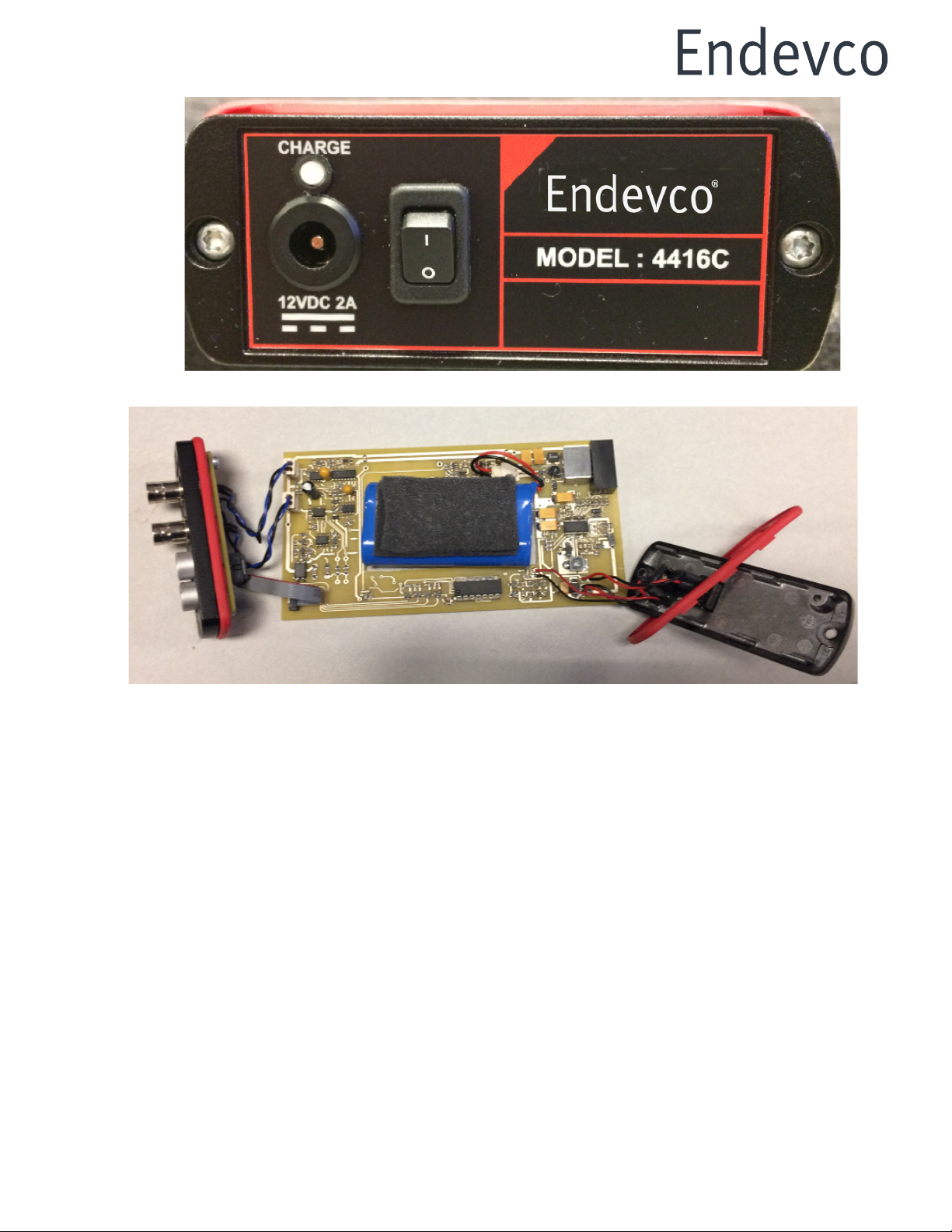
Photo 1. Front Panel
2. Detailed Description
2.1 Input
2.1.1 Connection
The 4416C supports transducers with integral electronics, i.e. ISOTRON®
and IEPE and also Piezoelectric (PE) types with the use of a remote charge
converter (RCC). Input connector is a standard BNC located on the front
panel with one side connected to signal ground. Power to the
transducer/RCC is available at the input socket in the form of a constant
current of 4.7mA with a compliance voltage of 24V dc.
2.1.2 Status
An indicator on the front panel shows the status of the input – if a transducer
is connected and functioning correctly the indicator will be “green”. If a fault
condition exists, the indicator will be “Red”. A fault condition exists when

IM4416C, Page
6
®
either the input is open circuit, i.e. no transducer connected, or if the input
is short circuit, i.e. a cable fault. During turn on, both green and red
conditions are cycled before the steady state is reached.
2.2 Output
2.2.1 Connection
The output connector is a standard BNC located on the front panel with
one side connected to signal ground. The case of the unit is also connected
to signal ground. If a connection to earth is required it should be made
through via the output connector to associated instrumentation.
2.2.2 Gain
Three levels of amplification (gain) are provided and selectable on the front
panel. The selected gain level is shown by the associated indicator.
2.2.3 Filter
A low pass filter is provided in the form of a second order Sallen Key. With
the filter indicator on, the filter is selected IN.
2.3 Power
Power for the Conditioner comes from an internal Li-ion cell pack, and a
supplied external universal power adapter. The power adapter functions as
a charger for the internal battery, but also will power the Conditioner, while
the battery is being charged. Battery charge and discharge are managed
by internal circuitry to provide a safe and effective environment for the
battery to operate. It is recommended that the charger be disconnected
once charging has stopped to maximize battery life.
Photo 2. Rear Panel
Warning! Only use the power adapter supplied with the 4416C for charging
otherwise internal damage may occur!

IM4416C, Page
7
®
2.3.1 Turn On
The conditioner is turned on and off by a switch on the rear panel. To turn
on, press the “1” and to turn off, press “0”. When turned on the Conditioner
will cycle through the front panel indicators lighting the gain indicators in
turn and lighting the filter indicator.
2.3.2 Low Battery Indicator
The battery Low indicator is on the front panel and will be “Red” when the
battery reaches a pre-determined level. At this point it is recommended that
the charger be connected. If the charger is not connected at this point the
unit will continue to function until a second predetermined battery level is
reached. At this point all power is turned off and no further operation is
possible. The battery must be recharged before reuse, or connected to
the charger and used while charging.
2.3.3 Battery Charge Indicator
The battery charge indicator is mounted above the charger socket on the
rear panel. While charging is in progress the indicator will be “green”. When
charging is complete the indicator is extinguished.
3. Operation
For optimum performance, it is recommended that the unit be fully charged
before using it the first time. Note: Ensure the Conditioner is turned off
before making any connecting to the 4416C. Once connections have been
made, the unit can be turned on with the switch located on the rear panel.
The unit will then cycle the front panel gain and filter indicators to verify all
are working.
3.1 Transducer Connection
The transducer/RCC is connected to the Input socket. A constant current
supply powers the transducer /RCC. When powered on, the
transducer/RCC will set a bias voltage at the input of the 4416C of
approximately 12Vdc (dependent on the transducer). The 4416C monitors
the dc bias to be within a pre-set range of 8V to 16 VDC. If the bias is within
the range the status indicator is turned Green and the system is ready to
use. If the bias is out of range, the status indicator is turned Red – an alert
condition exists. (This does not mean a sensor is bad, just verify the bias
voltage is acceptable.) Note: Some transducers can take 1 – 2 minutes
before the bias settles into range, and some Low Frequency RCC’s can
take as long as 5 minutes to reach their operating point.

IM4416C, Page
8
®
3.2 Output Connection
Measuring Instrumentation, i.e. data acquisition, data logger etc., should
be connected to the output socket using coaxial cables. Load impedance
should be no lower than 100kΩ to meet all specifications. Ideally, the
4416C should be placed near the measuring instrumentation to minimize
the effect of cable capacitance loading.
3.3 Gain Setting
Depressing the “Gain” switch cycles through the gain ranges of x1, x10 and
x100. The gain range selected is shown by the indicator above the range
turning Green. The gain together with the transducer sensitivity determines
the acceleration range available from the system and the output sensitivity,
i.e. for an accelerometer with a sensitivity of 10mV/g pk, and the maximum
output of the 4416C being 10V pk:
Gain = 1 Range = 1000g Output sensitivity = 10mV/g
Gain = 10 Range = 100g Output sensitivity = 100mV/g
Gain = 100 Range = 10g Output sensitivity = 1000mV/g
3.4 Filter Selection
A second order low pass filter is selected by depressing the filter switch.
This toggles the filter in and out. With the indicator Green, the filter is
selected IN. The Standard filter provides attenuation of -5% at
approximately 10kHz, and -3dB at 30 kHz for gains of 1 and 10, or 18kHz
for gain of 100. The filter maybe used to reduce the effects of HF noise
and aliasing in data acquisition systems.
3.5 Battery Charging
Ensure that both the Charger and Conditioner are turned OFF before
connecting. Plug the Charger connector into the socket on the rear panel
of the Conditioner. Turn on the charger. Charging is accomplished in two
stages:
Stage 1 – Fast Charge Mode
“Fast Charge Mode”, covers both constant current and constant voltage
modes and charges the battery to approximately 85% of its capacity in
approximately 3 hours. Once 85% capacity has been achieved, the
charging will automatically switch into “Stage 2”.
Stage 2 – Trickle Charge Mode
“Trickle Charge Mode” will deliver sufficient charge to top up the battery to
100% of its capacity in approximately 45 minutes.

IM4416C, Page
9
®
Once 100% capacity has been achieved the charge indicator will
extinguish. In the event of a fault with the battery charging circuit, or the
battery pack itself, the charge indicator will be “Red”. In this event, please
contact your local representative to arrange for the repair of the
Conditioner. Note: For any repair, return the charger with the unit to insure
all components are performing properly – the charger could be the problem
source.
The charging times are approximate and will vary depending on initial
battery charge state and temperature. If the Conditioner is turned on while
being charged, the power from the charger will be shared between
operation and charging with the priority given to its operation.
To conserve battery life, it is recommended that once the battery is fully
charged, the charger is disconnected.
4. Maintenance, Calibration and Repair
If the unit is suspected of not working or malfunctioning it can be checked
by use of the following circuit. This circuit should also be used when
performing a calibration of the unit.
1.1 Check Out Procedure
4.1.1 Equipment Required:
Signal Generator, static free mat, DMM and Oscilloscope
4.1.2 Instructions
• Ensure the battery is fully charged.
• Connect the circuit above to the input of the 4416C.
• Set the signal generator for 70mV rms at a frequency of 100Hz.
• Turn on the 4416C and select a gain of 1. Allow 5 minutes to stabilize.
• Measure with the DMM across the 2.5kΩ resistor for a voltage of
approximately 12V dc.
• Verify on the oscilloscope that an undistorted sine wave of approximately
100mV pk is displayed.

IM4416C, Page
10
®
• Select a gain of 10. Verify the signal on the oscilloscope is undistorted and
approximately 1V pk in amplitude.
• Select a gain of 100. Verify the signal on the oscilloscope is undistorted
and approximately 10V pk in amplitude.
• To verify the output noise, replace the signal generator with a short circuit.
• If any of the above conditions are not met, the unit should be considered
faulty and requires repair.
4.2 Repair
In the event that the Conditioner requires repair please contact your local
Sales Representative or distributor who will advise on the returns
procedure. Note: Return the charger with the Conditioner whenever repair
is required. The charger could be the source of the problem.
4.3 Battery Replacement
Battery life is > 300 cycles, which under typical operating conditions should
exceed 3 years. Should the battery need to be replaced please contact
your local Sales Representative or distributor who will advise on the returns
procedure.
The internal battery of the Model 4416C is located centrally within the case.
Replacement of the battery requires minimal skill but the greatest of care.
The following describes how to replace the internal battery.
Parts Required: Replacement Battery – Part Number EHM2107
Tools Required: Torx T10 Driver, Small sharp implement
4.3.1 Procedure
a. Using the small sharp implement, gently pry out and remove the plastic
screw covers located on the front panel, shown removed on the left side
and at the red circle on the right side of the front panel in Photo 3 below.
Do not discard the plastic covers.
b. Remove the two screws securing the front panel using the T10 TORX
driver. Gently pull the front panel away from the body – there are short
connecting wires behind the panel. Note: The gasket remains with the
panel.
c. In a similar manner, remove the two screws securing the rear panel using
the T10 TORX driver. Gently pull the front panel away from the body – there
are short connecting wires behind the panel, shown in Photo 4. Do not
discard the covers. (The wire connections can be disconnected if
preferred, but less stress on the cables is better.)
d. Gently rotate the rear panel at an angle, allowing it to be flat, to easily pass
through the case by pushing from the rear, extracting the entire assembly
from the front. The entire assembly and battery will slide out with the circuit

IM4416C, Page
11
®
board. A gasket goes with each panel. Place the entire circuit board
assembly on a static free surface, to prevent potential static damage to
components. See Photo 5.
e. Unplug the battery from the socket on the circuit board. See photo 5.
f. Locate the new battery and connect it to the socket on the circuit board.
g. Gently ease the rear panel and one gasket first, into the case, followed by
the circuit board and battery into the case, compressing the battery foam.
Note: The circuit board is located in the lower channel in the case, just
below the two mounting screw holes. See Photo 6.
h. Replace and secure the rear panel.
i. Replace and secure the front panel.
j. Replace all plastic screw covers.
k. Place the unit on charge.
l. Dispose of the original battery responsibly or return it to MSS for disposal.
Photo 3
IM4416C, Page
12
®
Photo 4
Photo 5

IM4416C, Page
13
®
Photo 6
5. Options and Accessories
5.1 Included Accessories
QSG4416C Quick Start Guide included
IM4416C Instruction Manual (Download from Endevco.com
website)
EHM2107 Universal power supply, with adaptors for USA, UK,
EURO, Japan and Australia
5.2 Options
EJ21 10-32 to BNC adapter
EHM2106 Replacement Battery
EHM2107 Replacement Universal power adapter
6. Compliance
6.1 ROHS to 2011/65/EU;
6.2 CE to EN61326-1:2013; CFR47 Pt 15 B Class A.
Table of contents
Popular Media Converter manuals by other brands


Extron electronics
Extron electronics Two InpuT VIdeo Scaler IN1502 Brochure & specs

National Instruments
National Instruments GPIB-422CV user manual

Cross Technologies
Cross Technologies 3116-22-23 instruction manual

Transition Networks
Transition Networks TR-CF-01 user guide

Atlona
Atlona AT-HDR-M2C installation guide

Z3 Technology
Z3 Technology Z3-HE4K-01-SW-02 User instructions


