Endress+Hauser RLN42 User manual

Products Solutions Services
Operating Instructions
RLN42
Two-channel NAMUR isolating amplifier with universal
power supply and relay signal output
BA02065K/09/EN/01.20
71526790
2020-12-17

Table of contents RLN42
2 Endress+Hauser
Table of contents
1 About this document ................ 3
1.1 Document function ..................... 3
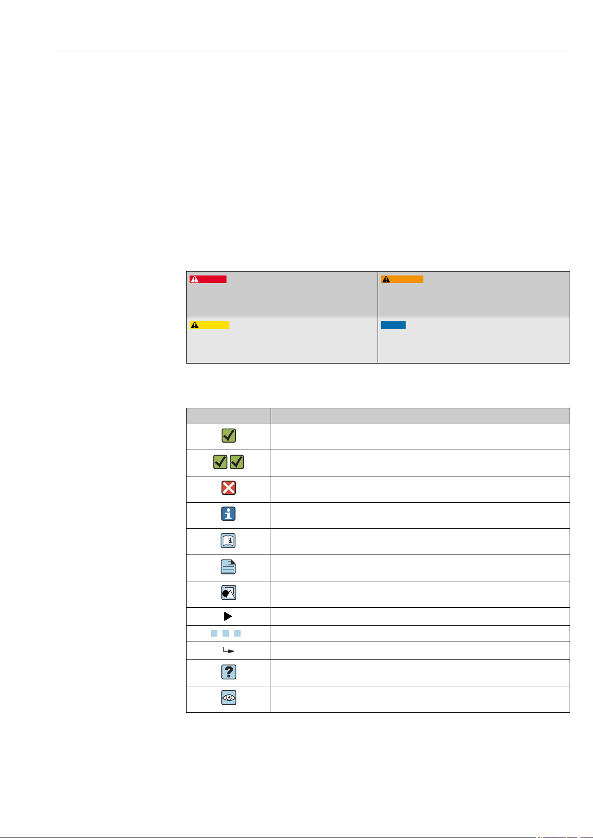
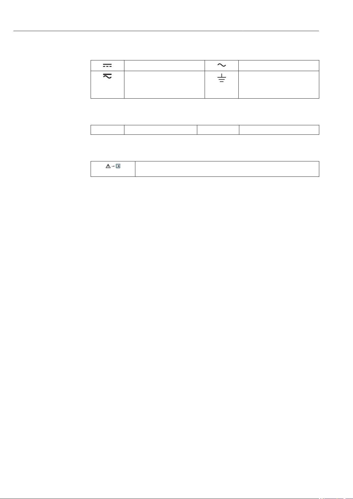
1.2 Symbols .............................. 3
2 Basic safety instructions ............ 5
2.1 Requirements for the personnel ............ 5
2.2 Designated use ........................ 5
2.3 Workplace safety ....................... 5
2.4 Operational safety ...................... 5
2.5 Product safety ......................... 6
2.6 Installation instructions .................. 6
3 Product descriptions ................ 7
3.1 Product description RLN42 ................ 7
4 Incoming acceptance and product
identification ....................... 7
4.1 Incoming acceptance .................... 7
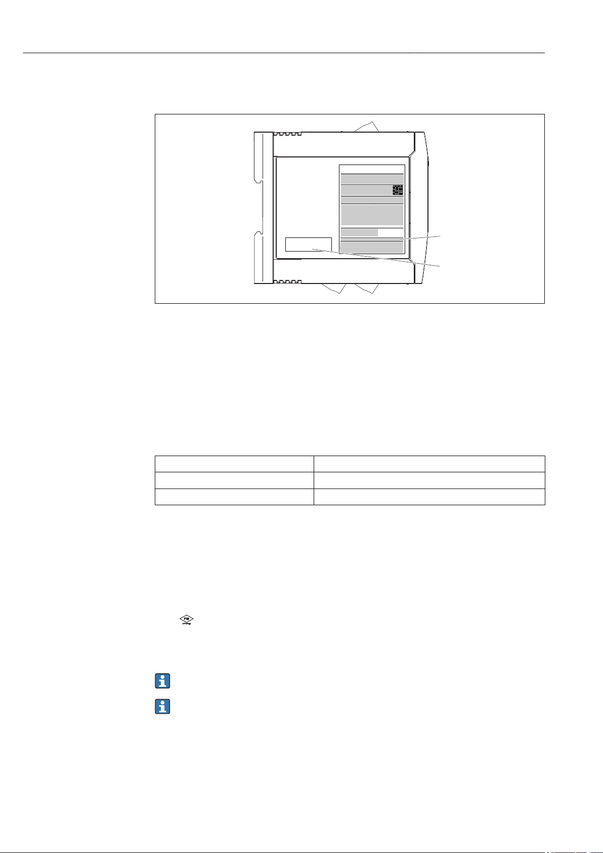
4.2 Product identification .................... 7
4.3 Scope of delivery ....................... 8
4.4 Certificates and approvals ................ 8
4.5 Storage and transport ................... 9
5 Installation ........................ 9
5.1 Installation conditions ................... 9
5.2 Installing a DIN rail device ................ 9
5.3 Disassembling the DIN rail device .......... 10
6 Electrical connection .............. 11
6.1 Connection conditions .................. 11
6.2 Quick wiring guide ..................... 12
6.3 Supply voltage ........................ 12
6.4 Post-connection check .................. 12
7 Operation options ................. 13
7.1 Display and operating elements ........... 13
8 Commissioning .................... 14
8.1 Post-installation check .................. 14
8.2 Switching on the device ................. 15
9 Diagnostics and troubleshooting ... 16
9.1 General troubleshooting ................. 16
10 Maintenance ...................... 16
11 Repair ............................ 16
11.1 General information ................... 16
11.2 Spare parts .......................... 16
11.3 Return .............................. 17
11.4 Disposal ............................ 17
12 Technical data .................... 18
12.1 Function and system design .............. 18
12.2 Input ............................... 18
12.3 Output ............................. 18
12.4 Power supply ......................... 19
12.5 Performance characteristics .............. 20
12.6 Installation .......................... 20
12.7 Environment ......................... 21
12.8 Mechanical construction ................ 22
12.9 Display and operating elements ........... 23
12.10 Ordering information ................... 24
12.11 Accessories .......................... 25
12.12 Certificates and approvals ............... 25
12.13 Supplementary documentation ............ 26
13 Appendix: system overview of RN
Series ............................ 27
13.1 Power supply of RN Series ............... 27
13.2 Applications of the isolating amplifiers ...... 27
Index .................................. 31

RLN42 About this document
Endress+Hauser 3
1 About this document
1.1 Document function
These Operating Instructions contain all the information that is required in various phases
of the life cycle of the device: from product identification, incoming acceptance and
storage, to mounting, connection, operation and commissioning through to
troubleshooting, maintenance and disposal.
1.2 Symbols
1.2.1 Safety symbols
DANGER
This symbol alerts you to a dangerous situation.
Failure to avoid this situation will result in serious or
fatal injury.
WARNING
This symbol alerts you to a dangerous situation.
Failure to avoid this situation can result in serious or
fatal injury.
CAUTION
This symbol alerts you to a dangerous situation.
Failure to avoid this situation can result in minor or
medium injury.
NOTICE
This symbol contains information on procedures and
other facts which do not result in personal injury.
1.2.2 Symbols for certain types of information
Symbol Meaning
Permitted
Procedures, processes or actions that are permitted.
Preferred
Procedures, processes or actions that are preferred.
Forbidden
Procedures, processes or actions that are forbidden.
Tip
Indicates additional information.
Reference to documentation
A
Reference to page
Reference to graphic
Notice or individual step to be observed
1.
,
2.
,
3.
… Series of steps
Result of a step
Help in the event of a problem
Visual inspection

About this document RLN42
4 Endress+Hauser
1.2.3 Electrical symbols
Direct current Alternating current
Direct current and alternating current Ground connection
A grounded terminal which, as far as
the operator is concerned, is
grounded via a grounding system.
1.2.4 Symbols in graphics
1, 2, 3,... Item numbers A, B, C, ... Views
1.2.5 Symbols at the device
Warning
Observe the safety instructions contained in the associated Operating Instructions

RLN42 Basic safety instructions
Endress+Hauser 5
2 Basic safety instructions
2.1 Requirements for the personnel
The personnel for installation, commissioning, diagnostics and maintenance must fulfill
the following requirements:
‣Trained, qualified specialists must have a relevant qualification for this specific function
and task.
‣Are authorized by the plant owner/operator.
‣Are familiar with federal/national regulations.
‣Before starting work, read and understand the instructions in the manual and
supplementary documentation as well as the certificates (depending on the
application).
‣Follow instructions and comply with basic conditions.
The operating personnel must fulfill the following requirements:
‣Are instructed and authorized according to the requirements of the task by the facility's
owner-operator.
‣Follow the instructions in this manual.
2.2 Designated use
2.2.1 NAMUR isolating amplifier
The NAMUR isolating amplifier is designed for the operation of proximity switches,
floating contacts and contacts with a resistive circuit. A relay is available per channel as
the signal output. The device is designed for installation on DIN rails in accordance with
IEC 60715.
2.2.2 Product liability
The manufacturer does not accept any responsibility for damage that results from non-
designated use and from failure to comply with the instructions in this manual.
2.3 Workplace safety
For work on and with the device:
‣Wear the required personal protective equipment according to federal/national
regulations.
2.4 Operational safety
Risk of injury!
‣Operate the device only if it is in proper technical condition, free from errors and faults.
‣The operator is responsible for interference-free operation of the device.
Modifications to the device
Unauthorized modifications to the device are not permitted and can lead to unforeseeable
dangers:
‣If modifications are nevertheless required, consult with the manufacturer.
Repair
To ensure continued operational safety and reliability:
‣Carry out repairs on the device only if they are expressly permitted.
‣Observe federal/national regulations pertaining to the repair of an electrical device.

Basic safety instructions RLN42
6 Endress+Hauser
‣Use only original spare parts and accessories from the manufacturer.
Hazardous area
To eliminate danger to persons or the facility when the device is used in the hazardous
area (e.g. explosion protection):
‣Check the nameplate to verify if the device ordered can be put to its intended use in the
hazardous area.
‣Observe the specifications in the separate supplementary documentation that is an
integral part of these instructions.
2.5 Product safety
This device is designed in accordance with good engineering practice to meet state-of-the-
art safety requirements, has been tested, and left the factory in a condition in which it is
safe to operate.
2.6 Installation instructions
• The device's IP20 degree of protection is intended for a clean and dry environment.
• Do not expose the device to mechanical and/or thermal stress that exceeds the specified
limits.
• The device is intended for installation in a cabinet or similar housing. The device may
only be operated as an installed device.
The cabinet must meet the fire protection housing requirements according to safety
standard UL/IEC 61010-1 and provide adequate protection against electric shock or
burns.
• To protect against mechanical or electrical damage, the device must be installed in an
appropriate housing with a suitable degree of protection according to IEC/EN 60529.
• The device fulfills the EMC regulations for the industrial sector (EMC Class A). It can
cause electrical interference if used in residential environments.
• During installation, repair and maintenance work, the device must be disconnected from
all effective power sources if the power sources are not SELV or PELV circuits.
• Only use copper cables with a permitted temperature range (60 °C / 75 °C) as the
connection cable.

RLN42 Product descriptions
Endress+Hauser 7
3 Product descriptions
3.1 Product description RLN42
3.1.1 Product design
NAMUR isolating amplifier
• The NAMUR isolating amplifier is designed for the operation of proximity switches
(according to EN 60947-5-6 (NAMUR)) and open and mechanical contacts with
resistive coupling elements. One relay (changeover) per channel is available as a signal
output. The power supply is designed as a universal power supply (UP).
• The device is optionally available with Ex approvals for the intrinsically safe operation of
proximity switches installed in the hazardous area. Separate Ex documentation (XA) is
supplied with these devices. Compliance with the installation instructions and
connection data in this documentation is mandatory!
• The device is optionally available for safety-oriented applications up to SIL 2 in
accordance with IEC 61508.
• A resistive coupling element (1 kΩ / 10 kΩ) is available as an optional accessory and can
be used to monitor line faults of sensors with mechanical contacts. The resistive coupling
element is installed onsite directly at the contact to be monitored or in the sensor
connection compartment.
4 Incoming acceptance and product
identification
4.1 Incoming acceptance
Check the following during incoming acceptance:
• Are the order codes on the delivery note and the product sticker identical?
• Are the goods undamaged?
• Do the nameplate data match the ordering information on the delivery note?
If one of these conditions is not met, please contact the manufacturer's sales office.
4.2 Product identification
The following options are available for identification of the device:
• Nameplate specifications
• Extended order code with breakdown of the device features on the delivery note
• Enter the serial number from the nameplate in the W@M Device Viewer
(www.endress.com/deviceviewer): all data relating to the device and an overview of the
Technical Documentation supplied with the device are displayed.
• Enter the serial number on the nameplate into the Endress+Hauser Operations App or
scan the 2-D matrix code (QR code) on the nameplate with the Endress+Hauser
Operations App: all the information about the device and the technical documentation
pertaining to the device is displayed.
4.2.1 Nameplate
The right device?

Incoming acceptance and product identification RLN42
8 Endress+Hauser
Compare and check the data on the nameplate of the device against the requirements of
the measuring point:
6
0044
iTEMP®TMT82
Made in Germany 2012 D-87484 Nesselwang
TAGXXXXXXXXXXX
TAGXXXXXXXXXXX
Order code: TMT82-xxx/xx
Ext. ord. cd.: XXXXXXXXXXX
Ser. no.: XXXXXXXXX
Input: 12-42 V
Current cunsum.: 23,0 mA
1
EH 08.001X
II3G Ex nA II T6/T5/T4 Ta= -40 ...+ 55/70/85°C
II3G Ex nL IIC T6/T5/T4 Ta= -40 ... +55/70/85°C
Install per XA0xxxxT/09/a3/xx.xx
7
1
2
3
4
5
7
8
A0041996
1 Nameplate (example of Ex version)
1 Product name and manufacturer ID
2 Order code, extended order code and serial number, DataMatrix 2D code, FCC-ID (if applicable)
3 Power supply and current consumption, output
4 Approval in hazardous area with number of the relevant Ex documentation (XA...)
5 Fieldbus communication logo
6 Firmware version and device revision
7 Approval logos
8 2 lines for the TAG name
4.2.2 Name and address of manufacturer
Name of manufacturer: Endress+Hauser Wetzer GmbH + Co. KG
Address of manufacturer: Obere Wank 1, D-87484 Nesselwang
Model/type reference: RLN42
4.3 Scope of delivery
The scope of delivery comprises:
• Device as per order
• Printed copy of the Brief Operating Instructions
• Optional: Functional safety manual (SIL mode)
• Additional documentation for devices which are suitable for use in the hazardous area
(0 1), such as Safety Instructions (XA...), Control or Installation Drawings (ZD...).
4.4 Certificates and approvals
For certificates and approvals valid for the device: see the data on the nameplate
Approval-related data and documents: www.endress.com/deviceviewer → (enter the
serial number)

RLN42 Installation
Endress+Hauser 9
4.4.1 Functional safety
A SIL version of the device is optionally available. It can be used in safety equipment in
accordance with IEC 61508 up to SIL 2.
Please refer to Safety Manual FY01035K for the use of the device in safety
instrumented systems according to IEC 61508.
Protection against modifications:
As it is not possible to disengage the operating elements (keys and DIP switches), a
lockable control cabinet is required for use in SIL applications. The cabinet must be
locked by key. A normal electrical cabinet key does not suffice for this purpose.
4.5 Storage and transport
When storing and transporting the device, pack it so that it is reliably protected
against impact. The original packaging provides optimum protection.
5 Installation
5.1 Installation conditions
5.1.1 Dimensions
The dimensions of the device are provided in the 'Technical data' section of the Operating
Instructions.
5.1.2 Mounting location
The device is designed for installation on 35 mm (1.38 in) DIN rails in accordance with IEC
60715 (TH35).
The device's housing provides basic insulation from neighboring devices for 300 Veff. If
several devices are installed side by side, this must be taken into consideration and
additional insulation must be provided if necessary. If the adjacent device also offers basic
insulation, no additional insulation is required.
NOTICE
‣When using in hazardous areas, the limit values of the certificates and approvals must
be observed.
For information on ambient conditions, see the "Technical data" section.
5.2 Installing a DIN rail device
The device can be installed in any position (horizontal or vertical) on the DIN rail without
lateral clearance from neighboring devices. No tools are required for installation. The use
of end brackets (type "WEW 35/1" or similar) on the DIN rail is recommended to fix the
device.

Installation RLN42
10 Endress+Hauser
1.
2.
3.
A0041736
2 Installing on DIN rail
1. Position the top DIN rail groove at the top end of the DIN rail.
2. While holding the front of the device horizontally, lower it until you hear the locking
clip of the device click into place on the DIN rail.
3. Pull gently on the device to check if it is correctly mounted on the DIN rail.
5.3 Disassembling the DIN rail device
1.
2. 3.
A0039696
3 Disassembling the DIN rail device
1. Insert a screwdriver into the tab of the DIN rail clip.
2. Use the screwdriver to pull down on the DIN rail clip as shown in the diagram.
3. Hold down the screwdriver to remove the device from the DIN rail.

RLN42 Electrical connection
Endress+Hauser 11
6 Electrical connection
6.1 Connection conditions
A flat-blade screwdriver is required to establish an electrical connection to screw or push-
in terminals.
0,5-0,6 Nm
5-7 lb In
7 mm (0,28")
AWG 24-14
0,2 -2,5 mm5 ² AWG 24-14
0,2 - ,5 mm5 2 ²
10 (0,39")mm
1.
2.
1.
1. 2.
3.
A0040201
4 Electrical connection using screw terminals (left) and push-in terminals (right)
LCAUTION
Destruction of parts of the electronics
‣Switch off power supply before installing or connecting the device.
NOTICE
Destruction or malfunction of parts of the electronics
‣ ESD - Electrostatic discharge. Protect the terminals from electrostatic discharge.
6.1.1 Special connection instructions
• Disconnecting units and auxiliary circuit protective systems with suitable AC or DC
values must be provided in the building installation.
• A switch/power circuit breaker must be provided close to the device and clearly marked
as a disconnecting unit for this device.
• An overcurrent protection unit (I≤16 A) must be provided in the installation.
• The voltages applied at the input are extra-low voltages (ELV). Depending on the
application, the supply and switching voltage at the relay output can be a dangerous
voltage (>30 V). Safe galvanic isolation to the other connections is provided for this
scenario.
For information on the connection data, see the "Technical data" section.

Electrical connection RLN42
12 Endress+Hauser
6.2 Quick wiring guide
N
L
24..230V
AC/DC
Out
In
5.1
4.24.1
3.3 2.2
3.1 2.13.2 2.3
5.3
1.2
1.1
14 14
11 1112 12
Ch1
Ch1
Ch2
Ch2
A0043438
5 Terminal assignment RLN42
6.3 Supply voltage
The modules are supplied with 24 to 230 VAC/DC via terminals 1.1 and 1.2.
6.4 Post-connection check
Device condition and specifications Notes
Are the device or cables free from damage (visual
check)?
--
Do the ambient conditions match the device
specification (e.g. ambient temperature, measuring
range, etc.)?
See "Technical data"
Electrical connection Notes
Does the supply voltage match the information on the
nameplate?
U = e.g. 24 to 230 VAC/DC
Are the power supply and signal cables connected
correctly?
--
Are all the screw terminals well tightened and have
the connections of the push-in terminals been
checked?
--

RLN42 Operation options
Endress+Hauser 13
7 Operation options
7.1 Display and operating elements
1
2
3
8
4
5
6
7
A0043446
6 Display and operating elements
1 Plug-in screw or push-in terminal
2 Green LED "On", power supply
3 Red LED "LF1", line fault of sensor cable 1
4 Red LED "LF2", line fault of sensor cable 2
5 Yellow LED "OUT1", status relay 1
6 Yellow LED "OUT2", status relay 2
7 DIP switches 1 to 4
8 DIN rail clip for DIN rail mounting
7.1.1 Local operation
Hardware settings / configuration
Any device settings using the DIP switch must be made when the device is de-
energized.
Direction of action
At the device, the direction of action (operating or closed circuit current behavior) can be
selected and line fault detection can be enabled or disabled via DIP switches.
DIP switch 1 = channel 1; DIP switch 3 = channel 2
All DIP switches are set to the "I" position when the device is delivered from the factory:
• I = normal phase (operating current behavior)
• II = inverse phase (closed circuit current behavior)
DIP switch 1:
• DIP switch position I = normal function: in the event of a 0-signal at the input, the relay
output (changeover) switches to the "non-conducting" state (NO contact is open) or
"conducting" state (NC contact is closed).
• DIP switch position II = inverse function: in the event of a 1-signal at the input, the relay
output (changeover) switches to the "non-conducting" state (NO contact is open) or
"conducting" state (NC contact is closed).
Line fault detection
DIP switch 2 = channel 1; DIP switch 4 = channel 2
I = line fault detection switched off - not permitted for safety-oriented applications!
II = line fault detection switched on

Commissioning RLN42
14 Endress+Hauser
If a line fault occurs, the relay is de-energized and the red LED "LF" flashes (NE 44).
NOTICE
Error detection malfunctions
‣For switch contacts with an open circuit, line fault detection (LF) must be disabled or
the corresponding resistance circuit (1 kΩ/10 kΩ) must be provided directly at the
contact. (
A
See the "Quick wiring guide" and "Accessories" sections of the Operating
Instructions)
7.1.2 Truth table, 2-channel
Sensor at input Input
circuit
DIP switch
Channel 1
DIP switch
Channel 2
Output
Relay
contact
LED Permitted
for
safety-
oriented
applicatio
ns
Switch Contacts
with
resistive
coupling
elements
NAMUR Status 1 2 3 4 NO
contact
NC
contact
OUT
yellow
LF red
Open Open Blocking OK I I I I Open Closed No
Closed Closed Conducti
ng
OK I I I I Closed Open X No
Open Open Blocking OK II I II I Closed Open X No
Closed Closed Conducti
ng
OK II I II I Open Closed No
Open Blocking OK I II I II Open Closed Yes
Closed Conducti
ng
OK I II I II Closed Open X Yes
Any state Any
state
Wire
break
I II I II Open Closed X Yes
Any state Any
state
Short
circuit
I II I II Open Closed X Yes
Open Blocking OK II II II II Closed Open X Yes
Closed Conducti
ng
OK II II II II Open Closed Yes
Any state Any
state
Wire
break
II II II II Open Closed X Yes
Any state Any
state
Short
circuit
II II II II Open Closed X Yes
8 Commissioning
8.1 Post-installation check
Before commissioning the device, ensure that all installation and post-connection checks
have been carried out.

RLN42 Commissioning
Endress+Hauser 15
NOTICE
‣Before commissioning the device, make sure that the supply voltage matches the
voltage specifications on the nameplate. Failure to perform these checks may result in
damage to the device caused by the incorrect supply voltage.
8.2 Switching on the device
Switch on supply voltage. The green LED display on the front of the device indicates that
the device is operational.

Diagnostics and troubleshooting RLN42
16 Endress+Hauser
9 Diagnostics and troubleshooting
9.1 General troubleshooting
Always start troubleshooting with the checklists below if faults occur after startup or
during operation. The checklists take you directly (via various queries) to the cause of the
problem and the appropriate remedial measures.
Due to its design, the device cannot be repaired. However, it is possible to send the
device in for examination. See the information in the "Return" section.
General errors
Error Possible cause Remedial action
Device is not responding. Supply voltage does not match the
specification on the nameplate.
Check the voltage directly using a
voltmeter and correct.
Connecting cables are not in contact
with the terminals.
Ensure electrical contact between the
cable and the terminal.
Electronics unit is defective. Replace the device.
The status LED on the DIN
rail device is lit or flashing
(red).
Diagnostics events as per NAMUR
NE107.
Check diagnostics events:
• LED is lit: diagnostic display, category
F
• LED flashing: diagnostic display,
categories C, S or M
The power LED on the DIN
rail device is not lit (green).
Power failure or insufficient supply
voltage.
Check the supply voltage and check if
wiring is correct.
10 Maintenance
No special maintenance work is required for the device.
Cleaning
A clean, dry cloth can be used to clean the device.
11 Repair
11.1 General information
Due to its design, the device cannot be repaired.
11.2 Spare parts
Spare parts currently available for the device can be found online at:
http://www.products.endress.com/spareparts_consumables. Always quote the serial
number of the device when ordering spare parts!
Type Order code
Plug-in terminal set, 3-pin, DIN rail interfaces - screw 71505345
Plug-in terminal set, 3-pin, DIN rail interfaces - push-in 71505346
Front cover 17.5 mm, DIN rail housing (5 pcs per pack) 71505348

RLN42 Repair
Endress+Hauser 17
11.3 Return
The requirements for safe device return can vary depending on the device type and
national legislation.
1. Refer to the website for more information:
http://www.endress.com/support/return-material
2. Return the device if repairs or a factory calibration are required, or if the wrong
device was ordered or delivered.
11.4 Disposal
If required by the Directive 2012/19/EU on waste electrical and electronic equipment
(WEEE), the product is marked with the depicted symbol in order to minimize the
disposal of WEEE as unsorted municipal waste. Do not dispose of products bearing this
marking as unsorted municipal waste. Instead, return them to the manufacturer for
disposal under the applicable conditions.

Technical data RLN42
18 Endress+Hauser
12 Technical data
12.1 Function and system design
Product description RLN42 Product design
NAMUR isolating amplifier
• The NAMUR isolating amplifier is designed for the operation of proximity switches
(according to EN 60947-5-6 (NAMUR)) and open and mechanical contacts with
resistive coupling elements. One relay (changeover) per channel is available as a signal
output. The power supply is designed as a universal power supply (UP).
• The device is optionally available with Ex approvals for the intrinsically safe operation of
proximity switches installed in the hazardous area. Separate Ex documentation (XA) is
supplied with these devices. Compliance with the installation instructions and
connection data in this documentation is mandatory!
• The device is optionally available for safety-oriented applications up to SIL 2 in
accordance with IEC 61508.
• A resistive coupling element (1 kΩ / 10 kΩ) is available as an optional accessory and can
be used to monitor line faults of sensors with mechanical contacts. The resistive coupling
element is installed onsite directly at the contact to be monitored or in the sensor
connection compartment.
Dependability We only provide a warranty if the device is installed and used as described in the
Operating Instructions.
12.2 Input
Version The following version is available:
2-channel
Input data (floating switch contacts with resistive coupling elements to connect NAMUR proximity
switches (IEC/EN 60947-5-6))
Switch points Blocking: < 1.2 mA
Conducting: > 2.1 mA
Line fault detection Line break:
0.05 mA < IIN < 0.35 mA
Short-circuit:
100 Ω < Rsensor < 360 Ω
Short-circuit current ~ 8 mA Open-circuit voltage ~ 8 VDC
Switching hysteresis < 0.2 mA
12.3 Output
Relay output data Relay output data
Contact version 1 changeover per channel Mechanical operating life 107 switching cycles
Maximum switching
voltage/current
250 VDC (2 A) / 120 VDC
(0.2 A) / 30 VDC (2 A)
Recommended minimum
load
5 V / 10 mA

RLN42 Technical data
Endress+Hauser 19
Maximum switching
capacity
500 VA Switching frequency (no
load)
≤ 20 Hz
Contact material AgSnO2, hard gold plated Direction of action Operating current or
closed circuit current
Signal on alarm
Output behavior in an alarm condition
If line fault detection is switched on and the line to the
sensor is disconnected or short-circuits, the relay de-
energizes in such a way that the output is set to the
safe, non-conducting state.
Line break in input 0.05 mA < IIN < 0.35 mA
Line short circuit in input 100 Ω < Rsensor < 380 Ω
Ex connection data See associated XA Safety Instructions
Galvanic isolation Input / output Peak value as per EN 60079-11
375 V
Input / power supply Peak value as per EN 60079-11
375 V
12.4 Power supply
Terminal assignment Quick wiring guide
N
L
24..230V
AC/DC
Out
In
5.1
4.24.1
3.3 2.2
3.1 2.13.2 2.3
5.3
1.2
1.1
14 14
11 1112 12
Ch1
Ch1
Ch2
Ch2
A0043438
7 Terminal assignment RLN42
Supply voltage The modules are supplied with 24 to 230 VAC/DC via terminals 1.1 and 1.2.
Important connection data Power supply
Supply voltage range 24 to 230 VAC/DC (-20% /
+10%, 0/50/60 Hz)
Maximum current
consumption
≤ 80 mA (230 VAC)
≤ 42 mA (24 VDC)
Power loss ≤ 1.3 W Power consumption ≤ 1.1 W
Terminals A flat-blade screwdriver is required to establish an electrical connection to screw or push-
in terminals.

Technical data RLN42
20 Endress+Hauser
0,5-0,6 Nm
5-7 lb In
7 mm (0,28")
AWG 24-14
0,2 -2,5 mm5 ² AWG 24-14
0,2 - ,5 mm5 2 ²
10 (0,39")mm
1.
2.
1.
1. 2.
3.
A0040201
8 Electrical connection using screw terminals (left) and push-in terminals (right)
Terminal design Cable design Cable cross-section
Screw terminals
Tightening torque: minimum 0.5
Nm/maximum 0.6 Nm
Rigid or flexible
(Stripping length = 7 mm (0.28 in) 0.2 to 2.5 mm² (24 to 14 AWG)
Flexible with wire end ferrules
(with or without plastic ferrule) 0.25 to 2.5 mm² (24 to 14 AWG)
Push-in spring terminals
Rigid or flexible
(Stripping length =
10 mm (0.39 in)
0.2 to 2.5 mm² (24 to 14 AWG)
Flexible with wire end ferrules
(with or without plastic ferrule)
0.25 to 2.5 mm² (24 to 14 AWG)
12.5 Performance characteristics
Response time Following a change of state at the input, the output adopts the safe state in ≤ 40 ms.
12.6 Installation
Mounting location The device is designed for installation on 35 mm (1.38 in) DIN rails in accordance with IEC
60715 (TH35).
The device's housing provides basic insulation from neighboring devices for 300 Veff. If
several devices are installed side by side, this must be taken into consideration and
additional insulation must be provided if necessary. If the adjacent device also offers basic
insulation, no additional insulation is required.
NOTICE
‣When using in hazardous areas, the limit values of the certificates and approvals must
be observed.
For information on ambient conditions, see the "Technical data" section.
Installing a DIN rail device The device can be installed in any position (horizontal or vertical) on the DIN rail without
lateral clearance from neighboring devices. No tools are required for installation. The use
of end brackets (type "WEW 35/1" or similar) on the DIN rail is recommended to fix the
device.
Table of contents