Energizer Homepower HP-6Series - Installation ManualEnergizer Homepower HP-6Series - Installation Manual
© Energizer 2022 © Energizer 2022V23-00220 V23-00220
14 15
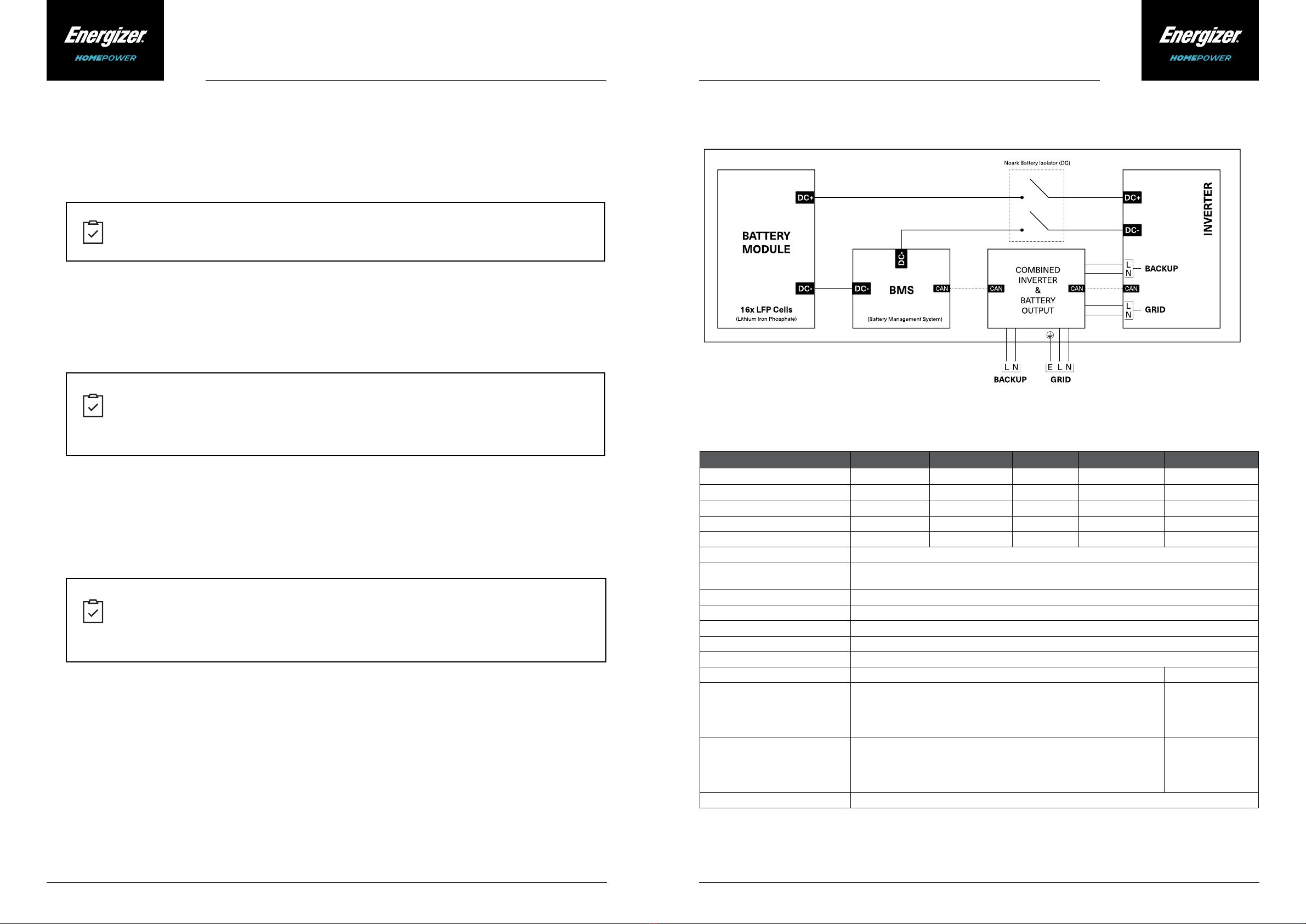
Table 2. Connections (Cable Information)
Required Tools & Supplies
Cable Gauge and Length Information
The following tools are required to carry out the installation for the Energizer Homepower (HP-6M/HP-6S):
The HP-6M unit requires cable connections for AC power, communication/ethernet (optional), Current
Transformers (CTs) and/or energy meters. For an HP-6S installation, additional DC Power cables & Battery
Communication (CAN) may also be required. Install the HP-6 system and other electrical components with minimal
cable lengths in-line with local codes and regulations.
• Personal Protective Equipment - Level 1 (safety glasses, gloves, protective footwear).
• M6, M8 or M10 hammer drill & drill bits for wall-mount brackets.
• Philips 2 screwdriver, Allen keys, cable stripping tool & box cutter.
• Spanner or socket wrench (if using dyna bolts).
• Crimping tool – CAT-5 cable/for RJ 45 connectors.
• Installation tools (spirit level, tape measure etc).
• Dyna bolts/heavy gauge wood screws - 6mm x 60mm.
• Lift equipment (capable of lifting 75 – 120 kg).
• Mobile phone running latest version of Apple (iOS) or Android operating system, enabled with
internet (mobile data).
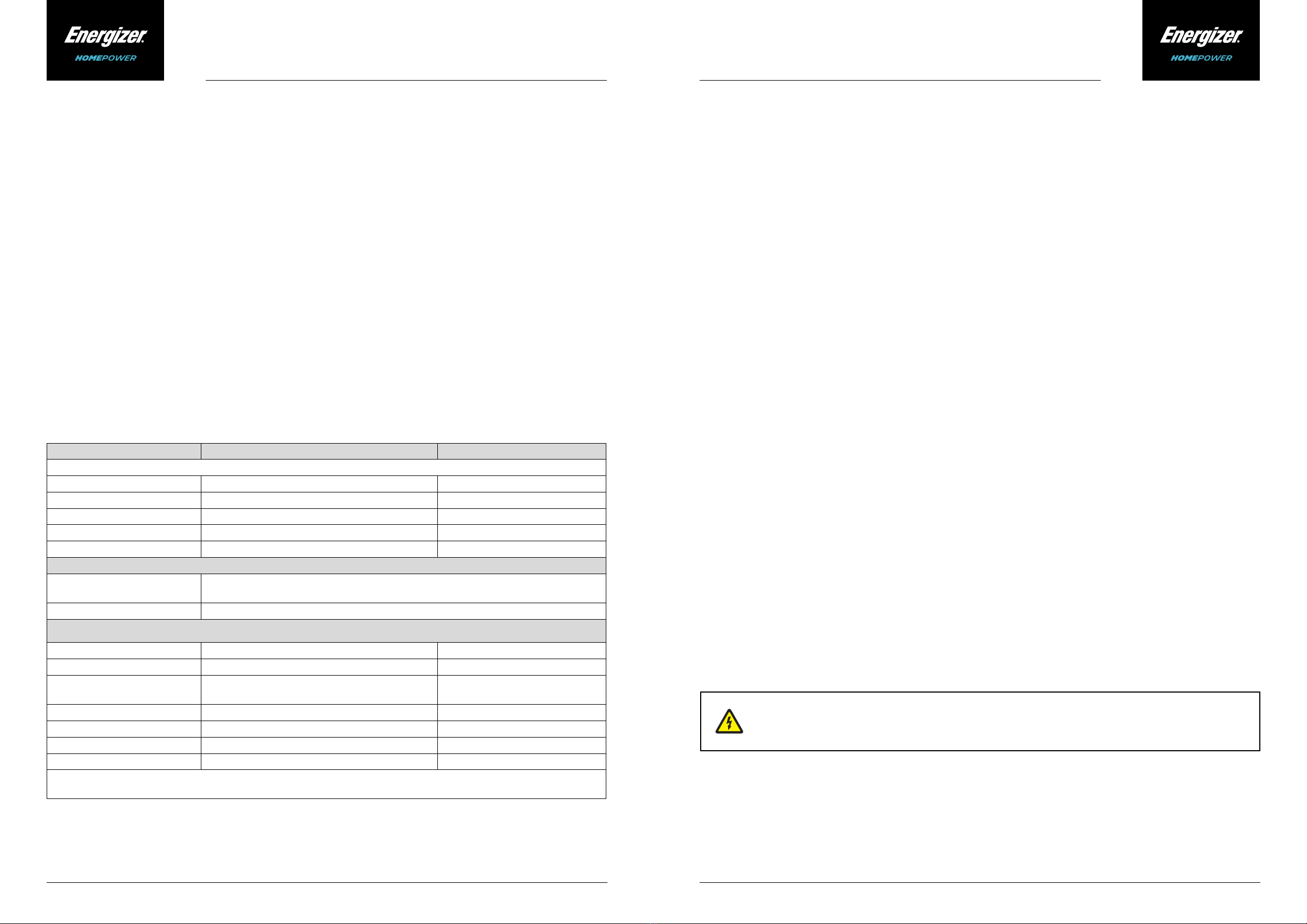
Terminal Connections Recommended Cable Gauge
Main Unit Installations (HP-6M)
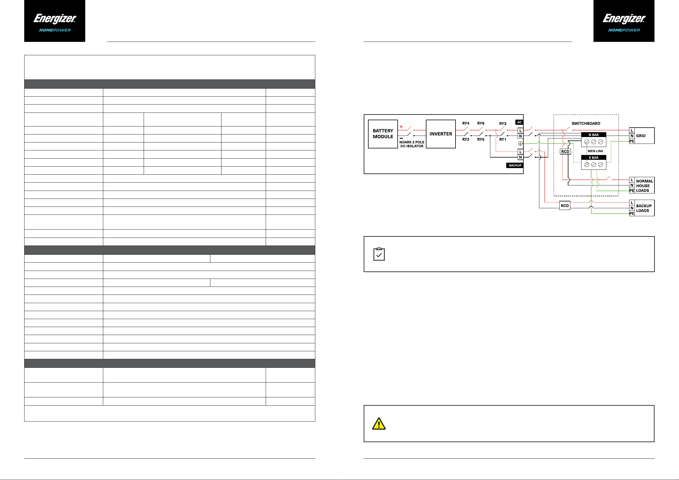
AC Power1(Grid - L/N) Grid terminals to electrical panel 4 - 6 mm2
AC Power1(Backup - L/N) Backup terminals to electrical panel (UPS/Backup) 4 - 6 mm2
Earth2Earth terminal to electrical panel 2.5 – 6 mm2
PV & Grid CTs (optional) Grid & PV CT Lead Extensions 0.2 – 1.5 mm2or CAT-5E/6 Shielded
Ethernet port (optional) HP-6M Ethernet port to Internet Router CAT-5E/6 Shielded
DVC Voltage Class
DVC-A Battery terminal, DRM terminal, 3-Phase communication terminal, CT (Grid/PV) terminal,
CAN terminal
DVC-C Backup terminal, Grid terminal
Combined Installations (HP-6M/1S, HP-6M/2S and HP-6M/3S)
AC Power1(Grid - L/N) Grid terminals to electrical panel 4 - 6 mm2
AC Power1(Backup - L/N) Backup terminals to electrical panel (UPS/Backup) 4 - 6 mm2
DC Power HP-6M (+ve) to HP-6S (+ve)
HP-6M (-ve) to HP-6S (-ve)
25 mm2
Earth1Earth terminal to electrical panel 2.5 – 4 mm2
CT Lead extension (optional) Grid & PV CT Lead Extensions 0.2 – 1.5 mm2or CAT-5E/6 Shielded
Ethernet port (optional) HP-6M Ethernet port to Internet Router CAT-5E/6 Shielded
Battery Communication (CAN) HP-6M to HP-6S CAT-5E/6
1Cables must be selected as per local and national codes or regulations.
2Earthing considerations as per local electrical codes. For HP-6S installations, 6 mm2 cable supplied with package.
The Energizer Homepower HP-6 Series system can be installed in both indoor and outdoor conditions and
has an Ingress Protection rating of IP65. However, it is recommended to select an appropriate installation
location to increase the safety, performance, and the lifespan of the system. Please ensure the below
requirements are met prior to installation.
The battery must be installed on a wall capable of supporting the size, mandatory clearances, and weight
of the Energizer Homepower HP-6 Series system. The clearances ensure sucient space availability for
electrical cabling and necessary airow.
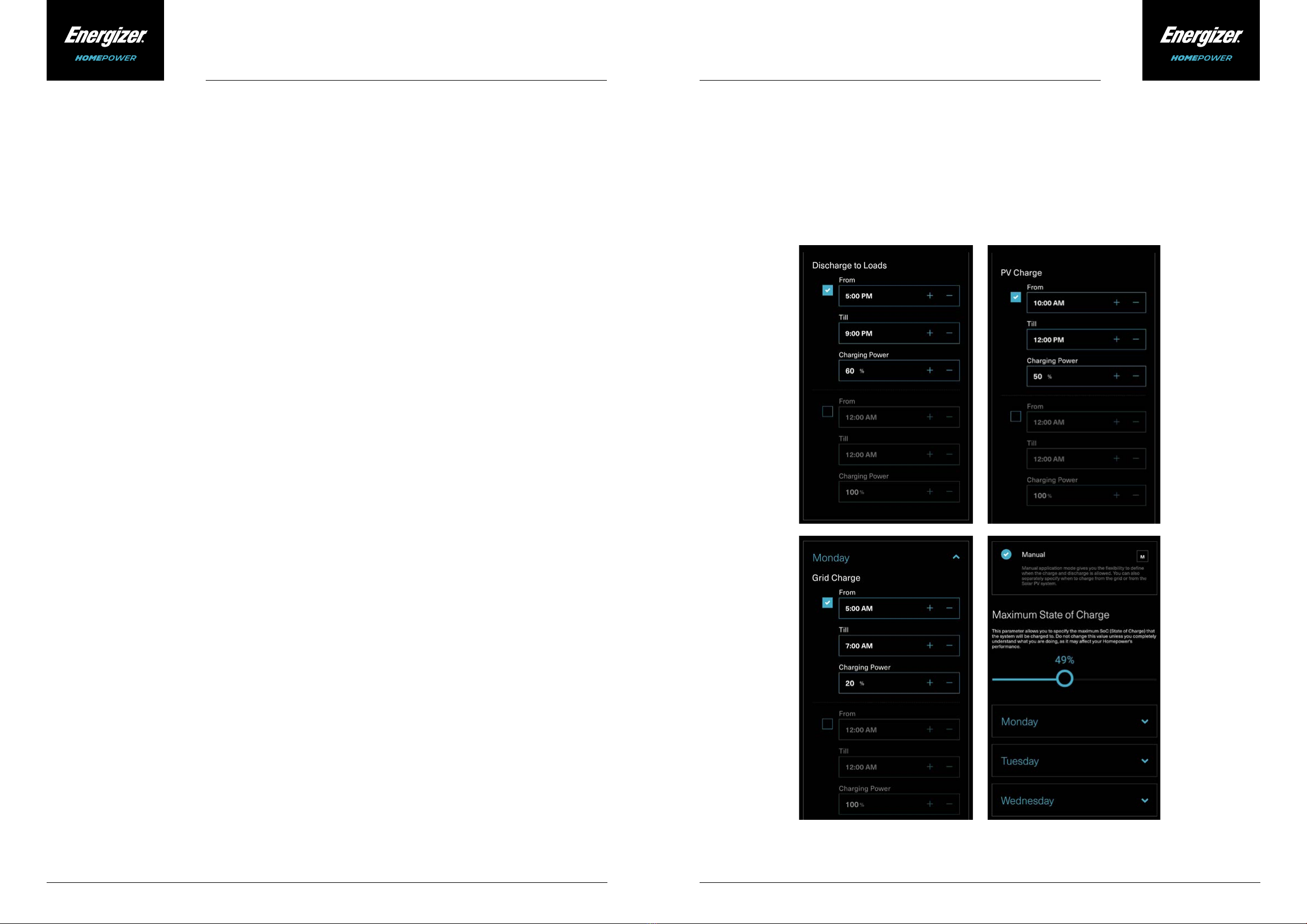
The Energizer Homepower HP-6 Series system can intelligently control the charge and discharge based on several
parameters including connected loads, solar generation, and external environmental conditions. It is sensitive
to the temperature variations & may limit charge or discharge based on internal cell temperature. Therefore, it is
recommended to avoid installations in locations that may be directly exposed to sunlight for prolonged periods of
time, and/or locations with sustained high or low temperatures. The Energizer Homepower HP-6 Series is designed
to operate optimally in an average ambient temperature range between 0°C to 30 °C.
4. Site Requirements
• If being installed indoors, it is recommended to install the Energizer Homepower HP-6 Series system in a
garage, ventilated storage area or a dedicated battery room.
• It is recommended to install the Energizer Homepower HP-6 Series on a switchboard that has both the Normal
Supply main switch and the Solar Supply main switch.
• The Energizer Homepower HP-6 Series units have unique enclosures to ensure even heat dissipation, so
please refrain from installing any additional external enclosures around the unit.
• Ensure that the Energizer Homepower HP-6 Series units are not installed on a wall that may have ammable or
corrosive equipment (including natural gas supply valves, gas meters or external air conditioning units).
• Energizer Homepower HP-6 Series units must be installed in a location with an ambient temperature range
between -20 to 50 °C.
• Do not install the Energizer Homepower HP-6 Series units in a location exposed to direct sunlight, extreme
rainfall, or snow.
• The site must have access to an internet connection via Wi-Fi, 4G/LTE and/or ethernet to ensure the Energizer
Homepower (HP-6M/HP-6S) is connected to the internet. The absence of such a connection or interruptions
over extended periods may aect the Warranty of the product.
• Furthermore, please refrain from installing the Energizer Homepower HP-6 Series in the following locations:
• Areas prone to ooding.
• Locations exposed to ammable or hazardous materials and gases.
• Cavity walls unable to support the weight of the battery.
• Areas of access, egress, and walkways.
• Closed spaces with minimal ventilation (such as under stairways).
• Areas exposed to high humidity, salty conditions & condensation values (over 85%).
• Location altitude > 2000 m.
In order to prevent any Electrical Shock or other related injuries, please ensure that Personal
Protective Equipment is used during the installation & ensure there are no electricity, plumbing
or gas pipelines on the wall selected for Battery Installation.