Energometrika EnergoM 400 User manual

Product Manual
Multi-channel Circuit Metering System
User Manual
Version:1.2
EnergoM 400
www.energometrika.ru
[email protected], тел.:+7(495)276-0510
ООО «Энергометрика»,

Product Manual
- 1 -
Read me
When you use series Multi-Channels Circuit Metering system, be sure to
carefully read this user manual, and be able to fully understand the implications, the
correct guidance of operations in accordance with user manual, which will help you make
better use this DC Energy Meter, and help to solve the various problems at the scene.
1. Before the meter turning on the power supply, be sure that the p ower supply within the
provisions of the instrument;
2.When installation, the current input terminal must non -open, voltage input terminals must
Non-short circuit;
3.Be sure the instrument wiring consistent with the internal system settings;
4.When c ommunicating with the PC, instrument communication parameters must be consistent
with the PC
●Please read this user manual carefully
●Please save this document
ООО «Энергометрика»,
[email protected], тел.:+7(495)276-0510
www.energometrika.ru

Product Manual
- 2 -
Directory
CONTENTS Page
1. - SUMMARIZE .............................................................................................................................. - 3 -
2. - SPECIFICATIONS...................................................................................................................... - 4 -
3.- INSTALLATION AND START-UP............................................................................................... - 6 -
3.1.- INSTALLATION...........................................................................................................................- 6-
3.2. -CONNECTION TERMINAL OF 7-
4. - SETUP PROCEDURE ................................................................................................................ - 8 -
4.1. -KEY OPERATION.......................................................................................................................- 8-
4.2. -SHOW ELECTRIC PARAMETERS ..................................................................................................- 8-
4.3.- PARAMETERS SETTING............................................................................................................- 10 -
4.4. -MENU STRUCTURE................................................................................................................. - 11-
5. - COMMUNICATION PROTOCOL.............................................................................................. - 13 -
5.1. -CONNECTION FOR THE RS485 BUS........................................................................................- 13 -
5.2. -MODBUS©PROTOCOL.........................................................................................................- 14 -
5.3. -REGISTERADDRESS TABLE.....................................................................................................- 15 -
6. - SAFETY CONSIDERATIONS................................................................................................... - 19 -
7. - MAINTENANCE........................................................................................................................ - 19 -
. .......................................................................................-
ООО «Энергометрика»,
[email protected], тел.:+7(495)276-0510
www.energometrika.ru

Product Manual
- 3 -
1. - SUMMARIZE
monitoring of building electrical loads with a low installation cost-p er-point by combining sub-
metering. The unit performs real-time metering, measures energy consumption, multi-tariff time-
of-use (TOU) and monitors power quality of 4 channels circuits for three phase circuits.
Advanced communications options including Modbus via RS485, I/O communications provide for
extensive reliable data exchange. Multiple units can be connected together to meter unlimited
departmental metering applications within office towers, condominiums, apartment buildings,
shopping centers and other multi-user environments.
Measurement Function
Voltage: Line Voltage; Phase Voltage
Current: Total Current; Current per channel
Power and Power Factor: Total power Reactive Power, Apparent Power, Power Factor and for
per channel
Frequency: System Frequency
Energy Function
Energy (kWh) measurement meeting international standards, accuracy is Class 1.0. It optional
Time of Use feature: 12 Seasons, 4 Tariffs record, max three-month data for each channel.
Over/Under Limit Alarming
Users can select parameters and set their set points. An alarm will be triggered when the set
point is reached, user can get the info from MODBUS reading.
Power Quality Analysis
Optional power quality parameters such as voltage and current THD, Odd harmonic distortion
(Total Odd HD), even harmonic distortion (Total Even HD), 2 ~ 21 times the harmonic content,
Current K-factor (KF), crest factor (CF), telephone interference factor (THFF), voltage and current
unbalance etc.
Communication and Network
Supports RS485 communication open protocol: Modbus RTU;
The Series provides a compact and robust metering solution, enable reliable
numberofcircuits.Theversatilityof metersareidealformulti-tenantor
ООО «Энергометрика»,
[email protected], тел.:+7(495)276-0510
www.energometrika.ru

Product Manual
- 4 -
2. - SPECIFICATIONS
Reference standard:
IEC60688-2012
IEC62053-21:2003
GBT 22264.1-2008 (IEC61557-12)
Accuracy standards
Parameter Accuracy A phase B phase C phase All
Voltage
Current
Active Power
Reactive Power
Apparent power
Power Factor
Active Energy
Reactive Energy
Frequency
0.2
0.2
0.5
0.5
0.5
0.5
1
2
0.1
Va
Aa1-12
Wa1-12
vara1-12
VAa1-12
PFa1-12
Vb
Ab1-12
Wb1-12
varb1-12
VAb1-12
PFb1-12
Vc
Ac1-12
Wc1-12
varc1-12
VAc1-12
PFc1-12
W1-12
var1-12
VA1-12
PF1-12
Wh1-12
varh1-12
Hz1-12
Notes: final metering accuracy depends one sampling CT and PT accuracy
Input
Voltage: Rated20~380V (need confirm before order)
Current: Rated ../100mA(optional ../0.333V, need confirm before order)
Frequency: 40-65Hz
Overload
Current: 1.2 times rated continuous;5 seconds for 10 times the rated
Voltage:1 seconds for 2 times the rated
Dielectric strength
Standard IEC 61010-1
2kV AC RMS 1 minute, between input / output / case / power supply
EMC Test standard Test voltage
Electrostatic discharge immunity
test: IEC-61000-4-2
level 4 8Kv
Electrical fast transient burst
immunity test
IEC61000-4-4
level 3 Input 1kV; Power supply 2kV
Surge (Shock) immunity test IEC61000-4-5
level 3 common mode test voltage
2kV
ООО «Энергометрика»,
[email protected], тел.:+7(495)276-0510
www.energometrika.ru

Product Manual
- 5 -
Temperature:-15C~ +55C
Humidity: RH 20%~95% (No condensation)
Storage Conditions
Temperature:-30C~+70C
Humidity: RH 20%~95%
Working Power
AC/DC 85-265V, 45-65Hz
Maximum power consumption3W
Dimensions
L ×H ×D =105X104X61.75mm
ООО «Энергометрика»,
[email protected], тел.:+7(495)276-0510
www.energometrika.ru
Product Manual
- 6 -
3.- INSTALLATION AND START-UP
The manual you hold in your hands contains information andwarnings that the user
should respect in order to guarantee a properoperation of all the instrument
functions and keep its safetyconditions. The instrument must not be powered and
used until its definitive assemblyis on the cabinet’s door.
Whether the instrument is not used as manufacturer’s specifications, theprotection of the
instrument can be damaged.
When any protection failure is suspected to exist (for example, it presentsexternal visible
damages),the instrument must be immediately powered off. In thiscase contact a qualified
service representative.
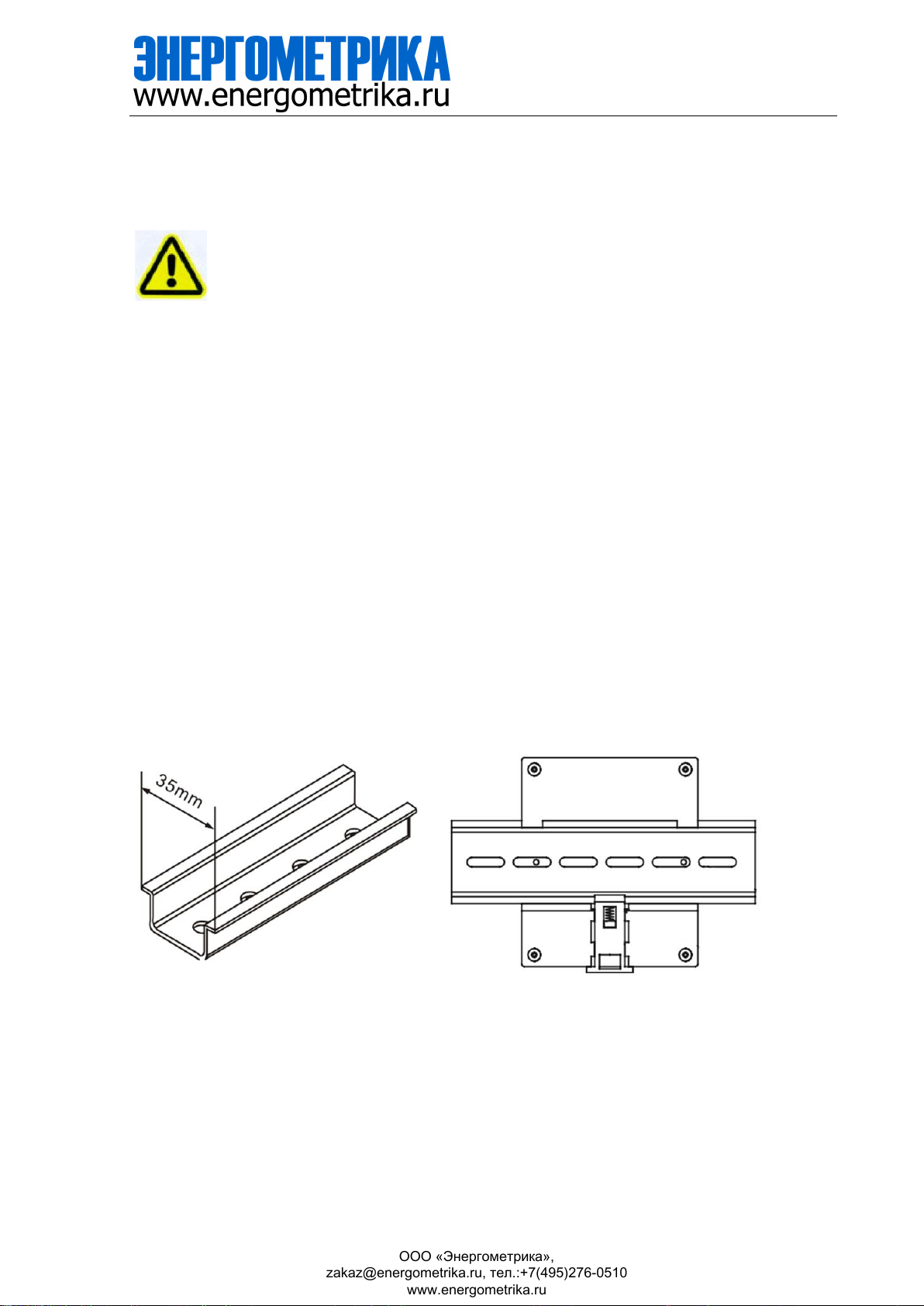
3.1.- Installation
Mounting
Instrument is to be mounted on35mm Din-rail. Keep all connections inside the cabinet.
Note that with the instrument powered on, the terminals could be dangerous totouch and cover
opening actions or elements removal may allow accessingdangerous parts.Therefore, the
instrument must not be used until this is completely installed.
Notes:
Auxiliary power:
85-265VAC/DC power interface for standard products. Please ensure that the auxiliary power
match meter access to prevent damage to the product.
meter with AUX power input, if not for a special statement, we provide the
ООО «Энергометрика»,
[email protected], тел.:+7(495)276-0510
www.energometrika.ru

Product Manual
- 7 -
Notes:
Meter use foolproof design, access terminal uses different styles block:
Terminal Size Style
Current sampling 3.81mm 6pin
Voltage sampling 7.62mm 4pin
AUX sampling 5.08mm 2pin
Digital output terminal 5.08mm 3pin
RS485 COMM 3.81mm 3pin
The current input pin need to access the CT, and output signal of CT is 0-100mA or 0~0.333V, CT
access have polarity to power direction. Please confirm your ordering meter types and prepare
related CT.
Digital output is passive load, inside relay can drive max 250 VAC(3A)/30VDC(3A) load, please
make sure connected load do not exceed this capacity.
Wiring diagram may be changed due to the special requirements of customers’ order, please
refer the label on the rear part.
If you are or sure or signs unclear, please contact:
3.2.-Connectionterminal
ООО «Энергометрика»,
[email protected], тел.:+7(495)276-0510
www.energometrika.ru

Product Manual
- 8 -
4. - SETUP PROCEDURE
4.1. - Key operation
“←” or “→” Screen switch or value increase/decrease
“SET” Menu enters or exit
“ ” Enter next menu or confirm the change
4.2. - Show electric parameters
parameters,
press “→” to switch another screen in this channel,
press “←” to switch parameter for channel 1-4
press " " to switch more details parameter in screen
screen roller logic as following:
Whenthe in monitor screen, user can use keypad switch shows the electrical
ООО «Энергометрика»,
[email protected], тел.:+7(495)276-0510
www.energometrika.ru


Product Manual
- 10 -
4.3.- Parameters Setting
When into the SETUP, use the keyboard to select different options and enter required
variables:
Press the key SET can enter the parameter setting. the screen ask access password (Default is
0001), then press can enter the menu.
The operation menu logic as following:
TheSETUPprocedureoftheisperformedbymeansofseveralSETUPoptions.
www.energometrika.ru
[email protected], тел.:+7(495)276-0510
ООО «Энергометрика»,

Product Manual
www.cqbluejay.com +86-023-67628702
- 11 -
4.4. - Menu Structure
level 1
Level 2
Level 3
Level 4
Description
Input
Setting
Wiring
mode 3P4L/3P3L2CT/3P3
L3CT input signal network
measurement
Rated volt 220V Default setting, cannot be
modified
Rated amp 0.100A(100mA) Default setting, cannot be
modified
PT ratio Last time set value 1~9999 Default 0001
CT ratio of
CH1 Last time set value 1~9999 Default 0050
CT ratio of
CH2 Last time set value 1~9999 Default 0050
CT ratio of
CH3
Last time set value
1~9999
Default 0050
CT ratio of
CH4 Last time set value 1~9999 Default 0050
Comm
Setting
Address 1~247 / Default 0001
Baud Rate 2400 / 4800 / 9600/
19200 / Default is 9600
Check
format n.8.1 / o.8.1 / e.8.1 / Factory default (n.8.1)
Alarm
Setting Alarm_1…5
Mode OFF / Upper Limit /
Lower Limit Total three mode
Delay / Alarm triggered time delay,
Default 001.0s
Parameter Ua/Ub/Uc/Uab/Ubc… Alarm triggered parameters
Value 0~9999
Default is 5500,value
related to secondary side
parameters, unit:
Volte- 0.1V;
Amp - 0.001A;
Active power - 0.1W;
Reactive power - 0.1VAR;
Power factor - 0.001;
Frequency - 0.01HZ;
hysteresis 0~9999 Default is 0050
Related channel CH1-4 Default CH1
Digital
outpit DO
Mode
Remote
Alarm_1...5
ON
OFF
Remote for RS485 control
Alarm_1…5 related to alarm
setting
ON/OFF are forced
act/release
Time Default 001.0sec In Alarm act for delay time,
in remote control mode for
pulse time
System
Settings
Password 0~9999 / Reset user password
Display MAN
Number 1~9 / Manual switching, or
automatic switching in
1~9sec
ООО «Энергометрика»,
[email protected], тел.:+7(495)276-0510
www.energometrika.ru

Product Manual
- 12 -
Backlight 1~5 / LCD backlight duration, unit
is min, default is 5
Clear Energy / Clear the record in meter
Contrast 1~9 / LCD display contrast,
default is 5
ООО «Энергометрика»,
[email protected], тел.:+7(495)276-0510
www.energometrika.ru

Product Manual
- 13 -
5. - COMMUNICATION PROTOCOL
5.1. - Connection for the RS485 BUS
The composition of the RS-485 cabling must be carried out with a meshed screen cable
(minimum 3 wire),diameter of not less than 0.5mm2, with a maximum distance of 1,200 m
between the BJ194… and the master unit. This Bus may connect a maximum of 32 BJ194…
Note: 1. For communication with the master unit, customers can choose the RS-232 to RS-485
converter to use
2. Full range of BJ-…meter RS485 PIN number is 58,59,60
3. Due to product modifications or custom requirements , the interface pin place may be
changed. For details, please refer to product labelon the rear board
ООО «Энергометрика»,
[email protected], тел.:+7(495)276-0510
www.energometrika.ru

Product Manual
- 14 -
5.2. - MODBUS © protocol
Modbus RTU Frame Format:
Address code
1 BYTE
Slave device address 1-247
Function code
1 BYTE
Indicates the function codes
like read coils / inputs
Data code
4 BYTE
Starting address, highbyte
Starting address, low byte
Number of registers, high byte
Number of registers, low byte
Error Check code
2 BYTE
Cyclical Redundancy Check
( CRC )
:
MODBUS FUNCTIONS
Code: Meaning: Description:
FUNCTION 03 Reading of n Words This function permits to read all
the electrical parameters of the
BJ194…series.
FUNCTION 06 Preset single Registers Write value in to the relevant
register
www.energometrika.ru
ООО «Энергометрика»,
[email protected], тел.:+7(495)276-0510

Product Manual
- 15 -
5.3. - Register Address Table
5.3.1- Basic Power Data—Primary Side (Read only)
Address Data Byte mode Instruction Status
0 CH1_Ua float 2 Channel_1 Phase to Line Voltage,
Unit: V
R
2 CH1_Ub float 2 R
4 CH1_Uc float 2 R
6 CH1_Uab float 2 Channel_1 Phase to Phase Voltage,
Unit: V
R
8 CH1_Ubc float 2 R
10 CH1_Uca float 2 R
12 CH1_Ia float 2 Channel_1 Three phase Current,
Unit: A
R
14 CH1_Ib float 2 R
16 CH1_Ic float 2 R
18 CH1_Pa float 2 Channel_1 Individual phase active
power,
Unit: kW
R
20 CH1_Pb float 2 R
22 CH1_Pc float 2 R
24 CH1_P∑float 2 Channel_1 Total active power,
Unit: kW R
26 CH1_Qa float 2 Channel_1 Individual phase reactive
power, Unit: kVar
R
28 CH1_Qb float 2 R
30 CH1_Qc float 2 R
32 CH1_Q∑float 2 Channel_1 Total reactive power,
Unit: kVar R
34 CH1_Sa float 2 Channel_1 Individual apparent power,
Unit: kVA
R
36 CH1_Sb float 2 R
38 CH1_Sc float 2 R
40 CH1_S∑float 2 Channel_1 Total apparent power,
Unit: kVA R
42 CH1_PFa float 2 Channel_1 Individual power factor,
0~1.000
R
44 CH1_PFb float 2 R
46 CH1_PFc float 2 R
48 CH1_PF∑float 2 Channel_1 Total power factor,
0~1.000 R
50 CH1_FR float 2 Channel_1 Frequency,
Unit:0.01Hz R
52 CH1_EpZ+ float 2 Channel_1 Total positive active energy,
Unit: kWh R
54 CH1_EpZ- float 2 Channel_1 Total negative active energy,
Unit: kVarh R
56 CH1_EqZ+ float 2 Channel_1 Total p ositive reactive
energy,
Unit: kVarh R
58 CH1_EqZ- float 2 Channel_1 Total n egative reactive
energy,
Unit: kWh R
60 CH1_EpA+ float 2 Channel_1 A phase positive active
energy,
Unit: kWh R
62 CH1_EpA- float 2 Channel_1 A phase negative active
energy, R
ООО «Энергометрика»,
[email protected], тел.:+7(495)276-0510
www.energometrika.ru
Product Manual
- 16 -
Unit: kVarh
64 CH1_EqA+ float 2 Channel_1 A phase positive reactive
energy,
Unit: kVarh R
66 CH1_EqA- float 2 Channel_1 A phase negative reactive
energy,
Unit: kWh R
68 CH1_EpB+ float 2 Channel_1 B phase positive active
energy,
Unit: kWh R
70 CH1_EpB- float 2 Channel_1 B phase negative active
energy,
Unit: kVarh R
72
CH1_EqB+
float
2
Channel_1 B phase positive reactive
energy,
Unit: kVarh
R
74 CH1_EqB- float 2 Channel_1 B phase negative reactive
energy,
Unit: kWh R
76 CH1_EpC+ float 2 Channel_1 C phase positive active
energy,
Unit: kWh R
78 CH1_EpC- float 2 Channel_1 C phase negative active
energy,
Unit: kVarh R
80 CH1_EqC+ float 2 Channel_1 C phase positive reactive
energy,
Unit: kVarh R
82 CH1_EqC- float 2 Channel_1 C phase negative reactive
energy,
Unit: kWh R
100-182 CH2_parameter float 2 Channel_2 parameter, structure refer to
Channel_1 R
200-282 CH3_parameter float 2 Channel_3 parameter, structure refer to
Channel_1 R
300-382 CH4_parameter float 2 Channel_4 parameter, structure refer to
Channel_1 R
5.3.2- Meter status data
Address Data Byte mode Instruction Status
1200 Digital output int 1 0: without act
1: active for trig R
1202 Alarm int 1 0: without alarm 1: Alarm trigged
Bit 0~4 show Alarm_1~5 status R
1203(R/
W) DO working
mode int 1
0: Remote control
1: Related to Alarm_1
2: Related to Alarm_2
3: Related to Alarm_3
4: Related to Alarm_4
5: Related to Alarm_5
6: trig to closed
7: trig to opened
R/W
1204 DO time delay int 1 In alarm mode: 0.0-999.9sec
In remote control mode: R/W
ООО «Энергометрика»,
[email protected], тел.:+7(495)276-0510
www.energometrika.ru
Product Manual
- 17 -
0 for Level output:
other value for pulse width
0.1-999.9sec
1240 Wiring mode int 1 0: 3P4W
1: 3P3W-2CT
2: 3P3W-3CT R
1241 Voltage range int 1 Unit: V R
1242 Current range int 1 Unit: mA R
1243 PT ratio int 1 Range: 1-9999 R
1244 CT of CH1 int 1 Range: 1-9999 R
1245 CT of CH2 int 1 Range: 1-9999 R
1246 CT of CH3 int 1 Range: 1-9999 R
1247 CT of CH4 int 1 Range: 1-9999 R
5.3.3 - Voltage harmonic (max 21th)
Address Data Byte mode Instruction Status
1300 THDUa int 1 A-phase Voltage THD, unit 0.1% R
1301 THDUb int 1 B-phase Voltage THD R
1302 THDUc int 1 C-phase Voltage THD R
1303
TOHDUa
int
1
A-phase Voltage odd harmonic total
distortion, unit 0.1%
R
1304 TOHDUb int 1 B-phase Voltage odd harmonic total
distortion R
1305 TOHDUc int 1 C-phase Voltage odd harmonic total
distortion R
1306 TEHDUa int 1 A-phase Voltage even harmonic total
distortion, unit 0.1% R
1307 TEHDUb int 1 B-phase Voltage even harmonic total
distortion R
1308 TEHDUc int 1 C-phase Voltage even harmonic total
distortion R
1320-1339 HUa int 20 A phase voltage harmonic ratio for 2 to
21th, unit 0.1% R
1340-1359 HUb int 20 B phase voltage harmonic ratio for 2 to
21th R
1360-1379 HUc int 20 C phase voltage harmonic ratio for 2 to
21th R
5.3.4 - Current harmonic (max 21th)
Address Data Byte mode Instruction Status
1400 THDIa1 int 1 Channel_1 A-phase Current THD , unit
0.1% R
1401 THDIb1 int 1 Channel_1 B-phase Current THD R
1402 THDIc1 int 1 Channel_1 C-phase Current THD R
1403 TOHDIa1 int 1 Channel_1 A-phase Current odd
harmonic total distortion, unit 0.1% R
1404 TOHDIb1 int 1 Channel_1 B -phase Current odd
harmonic total distortion R
1405 TOHDIc1 int 1 Channel_1 C -phase Current odd
harmonic total distortion R
1406 TEHDIa1 int 1 Channel_1 A-phase Current even
harmonic total distortion, unit 0.1% R
ООО «Энергометрика»,
[email protected], тел.:+7(495)276-0510
www.energometrika.ru

Product Manual
- 18 -
1407
TEHDIb1
int
1
Channel_1 B -phase Current even
harmonic total distortion
R
1408 TEHDIc1 int 1 Channel_1 C -phase Current even
harmonic total distortion R
1420-1439 HIa1 int 20 Channel_1 A phase Current harmonic
ratio for 2 to 21th, unit 0.1% R
1440-1459 HIb1 int 20 Channel_1 B phase Current harmonic
ratio for 2 to 21th R
1460-1479 Hic1 int 20 Channel_1 C phase Current harmonic
ratio for 2 to 21th R
1500-1579 CH2 Harmonic int 20 Channel_2 harmonic value, structure
refer to Channel_1 R
1600-1679 CH3 Harmonic int 20 Channel_3 harmonic value, structure
refer to Channel_1 R
1700-1779 CH4 Harmonic int 20 Channel_4 harmonic value, structure
refer to Channel_1 R
5.3.5 –Special operation
Address Data Byte mode Instruction Status
3000 Reset energy
counter int 1 Send code 0x0A0A (DEC 2570) to clear
all the energy counter W
ООО «Энергометрика»,
[email protected], тел.:+7(495)276-0510
www.energometrika.ru

Product Manual
- 19 -
6. - SAFETY CONSIDERATIONS
All installation specification described at the previous chaptersnamed:
INSTALLATION AND STARTUP, INSTALLATION MODESand
SPECIFICATIONS.
Note that with the instrument powered on, the terminals could be dangerous to touching and
cover opening actions or elements removal may allow accessing dangerous parts. This
instrument is factory-shipped at proper operation condition.
7. - MAINTENANCE
or repairing action should be done when the instrument open and powered on, should those
actions are essential, high-qualified operators must perform them.
Before any adjustment, replacement, maintenance or repairing operation is carried out; the
instrument must be disconnected from any power supply source.
When any protection failure is suspected to exist, the instrument must be immediately put out
of service. The instrument’s design allows a quick replacement incase of any failure.
Thedoesnotrequireanyspecialmaintenance.Noadjustment,maintenance
ООО «Энергометрика»,
[email protected], тел.:+7(495)276-0510
www.energometrika.ru
Table of contents
Other Energometrika Measuring Instrument manuals


Popular Measuring Instrument manuals by other brands


PCB Piezotronics
PCB Piezotronics 353B34 Installation and operating manual

Fieldpiece
Fieldpiece SC260 Operator's manual

Joinwit
Joinwit JW8001 user manual

SST
SST OXY-Flex user guide

Associated Research
Associated Research hypot III 3605 Operation and service manual

Fluke
Fluke WaveRunner Getting started guide


