Energy Storage Technologies HemaCool HMC-MIL-1 Troubleshooting guide

HEMACOOLTM Model HMC-MIL-1 Operations Manual August 2003
Energy Storage Technologies, Inc. Dayton, Ohio 45459
OPERATION & MAINTENANCE
of the
TWO-TEMPERATURE Military HemaCool™
A Field Rugged, Advanced Technology Refrigerator/Freezer
For
Blood, Blood Products & Medical Supplies
Model HMC-MIL-1
ENERGY STORAGE TECHNOLOGIES, INC.
7610 McEwen Road
Dayton, Ohio 45459 U.S.A.
www.estglobal.com
Telephone: (937) 312-0114
Fax: (937) 312-1277
August 2003

HEMACOOLTM Model HMC-MIL-1 Operations Manual August 2003
Energy Storage Technologies, Inc. Dayton, Ohio 45459
1
This manual is solely for the HemaCool™ HMC-MIL-1. It provides a set of
instructions for the unpacking, operating, data logging and routine maintenance of
the unit.
For assistance with this unit – or any Energy Storage Technologies product -- email

HEMACOOLTM Model HMC-MIL-1 Operations Manual August 2003
Energy Storage Technologies, Inc. Dayton, Ohio 45459
2
CAUTIONS:
•USE THE COOL (+4.0±1.5°C [39.2° ±2.7°F]) TEMPERATURE SETTING
ONLY WITH MATERIALS THAT MUST BE STORED ABOVE
FREEZING.
USE THE FREEZE (–22+0/–6°C [–7.6+0/–11°F]) TEMPERATURE
SETTING ONLY FOR MATERIALS THAT MUST BE STORED
FROZEN.
•THE TEMPERATURE SETTING TOGGLE SWITCH IS A LOCKING
TYPE SWITCH, AND YOU MUST PULL OUT ON THE HANDLE TO
CHANGE IT. DO NOT FORCE!
•IF UNIT IS STORED INVERTED OR ON ITS SIDE, ALLOW IT TO SIT
UPRIGHT AT LEAST TWO HOURS BEFORE OPERATING IT.
•DO NOT TILT THE UNIT OVER 30° WHILE OPERATING.
•FOR MAXIMUM EFFICIENCY DO NOT TILT AT ALL DURING
OPERATION.
•DO NOT STORE THE UNIT IN AMBIENT TEMPERATURES BELOW
-30°C (-22°F) OR OVER 65°C (149°F).
•DO NOT OPERATE THE UNIT IN THE REFRIGERATOR MODE IN
AMBIENT TEMPERATURES BELOW -20°C (-4°F) OR ABOVE 49°C
(120°F).
•DO NOT SIT OR STAND ON THE UNIT.
•DO NOT TRANSPORT UNIT WITHOUT THE OUTER LID IN PLACE
AND ALL INNER LID AND OUTER LID LATCHES CLOSED.
•HEMACOOL UNITS MAY BE SAFELY STACKED TWO UNITS HIGH.
•DO NOT SUBMERGE THE UNIT IN WATER.

HEMACOOLTM Model HMC-MIL-1 Operations Manual August 2003
Energy Storage Technologies, Inc. Dayton, Ohio 45459
3
TABLE OF CONTENTS
Subject Page
A. Unit Overview 4
B. Unpacking and Readying for Operation 6
C. Starting the HemaCool™ 10
D. The HemaCool™ Display and Alarm Functions 14
E. Data Logger and Pocket PC Download 17
F. HemaCool™ Maintenance 20
G. HemaCool™ Specifications 29
H. Warranty 30
Appendix A – PCM Wall Option 31
Appendix B – Tools and Parts 33
If the user has questions about the unit, he/she should contact Energy Storage
Technologies, Inc., by phone at 937-312-0114; by fax at 937-312-1277; or by email at
HEMACOOLTM Model HMC-MIL-1 Operations Manual August 2003
Energy Storage Technologies, Inc. Dayton, Ohio 45459
4
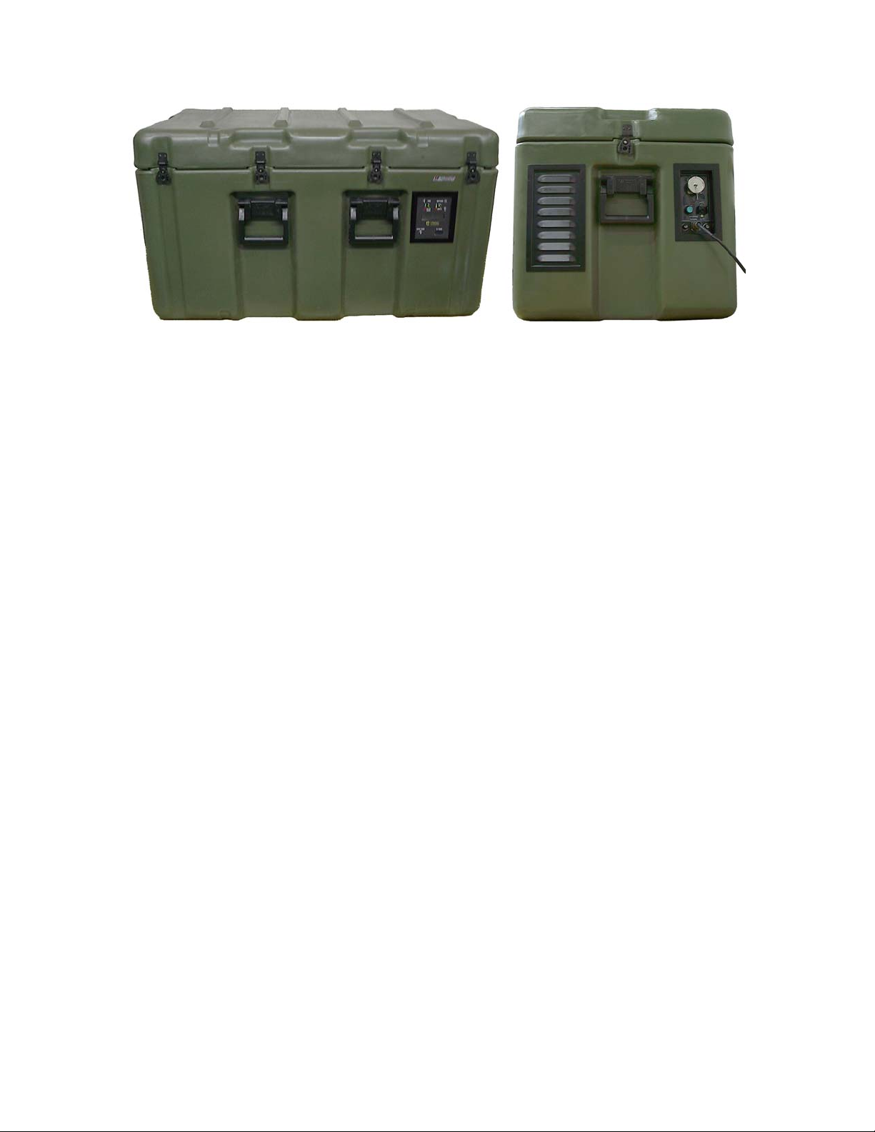
Fig. 1. Mil version HemaCool™ side and control end
A. UNIT OVERVIEW:
The HemaCool™ is designed to preserve liquid or frozen blood products and medical
supplies. HemaCool™ provides exceptional field storage through its combination of
superior insulation technology and temperature controls based on microcontroller solid-
state electronics.
The HemaCool™ is portable and self-powered, utilizing internal gel cell batteries. The
system will accept electrical power from multiple sources, e.g. 12-24VDC from batteries
or other sources at the AUX input, solar panels, or a wide range of grid power standards
(any combination of 90–264 VAC and 47–63 Hz line frequencies). The unit is designed
with solar panel lightning protection.
If the unit is fully stocked – and no power is applied [unit off] – it will take more than
two hours for the internal payload temperature to rise to 6°C (43°F) in an ambient
temperature of 49°C (120°F). With the optional thermal barrier in place, the unit is also
capable of chilling five (5) units of freshly transfused blood to 6°C (43°F) within eight
(8) hours.

HEMACOOLTM Model HMC-MIL-1 Operations Manual August 2003
Energy Storage Technologies, Inc. Dayton, Ohio 45459
5
The HemaCool™ will perform in either COOL or FREEZE mode.
•In COOL mode (+4.0°) the unit -- provided its two internal 20 amp-hour batteries
are properly charged -- will maintain a temperature range of 1°C to 6°C (34°F to
43°F) for more than 24 hours, at +24°C ambient temperature (75°F).
•In FREEZE mode (-22° ) the unit – provided its two internal 20 amp-hour
batteries are properly charged – will keep blood products frozen for more than
eight hours, at an ambient temperature of +24°C (75°F). (This colder operation
does, however, reduce the battery-powered hold time. See specifications at the
end of this document.)
For additional payload security, the HemaCool™ is also equipped with an internal
heater that will prevent refrigerated payload from freezing if the unit is in an
environment that is below 1°C (34°F), but no lower than –20°C (-4°F).
NOTE: The standard default temperature scale setting for the HemaCool™ is
Celsius (°C). The unit may be special ordered to display temperature in the
Fahrenheit (°F) scale.

HEMACOOLTM Model HMC-MIL-1 Operations Manual August 2003
Energy Storage Technologies, Inc. Dayton, Ohio 45459
B. UNPACKING AND READYING THE HemaCool™ FOR OPERATION:
Remove the HemaCool™ from its crating materials. Unlatch the outer lid. This lid has
10 latches, one on each end and four on each side. Flip out and rotate the key tabs on
each latch until each latch claw has released its hasp.
Fig. 2. To unlatch the outer lid: flip up latch tab and rotate ½ turn left. Drop open.
Fig. 3. Under the exterior lid the HemaCool™ is divided into three compartments.
The HemaCool™ is shipped with its internal batteries disconnected. Before initial use
the batteries must be connected. To do this:
1. Open the compartment lid labeled “Cable And Manual Storage” (upper half of
Fig. 4).

HEMACOOLTM Model HMC-MIL-1 Operations Manual August 2003
Energy Storage Technologies, Inc. Dayton, Ohio 45459
7
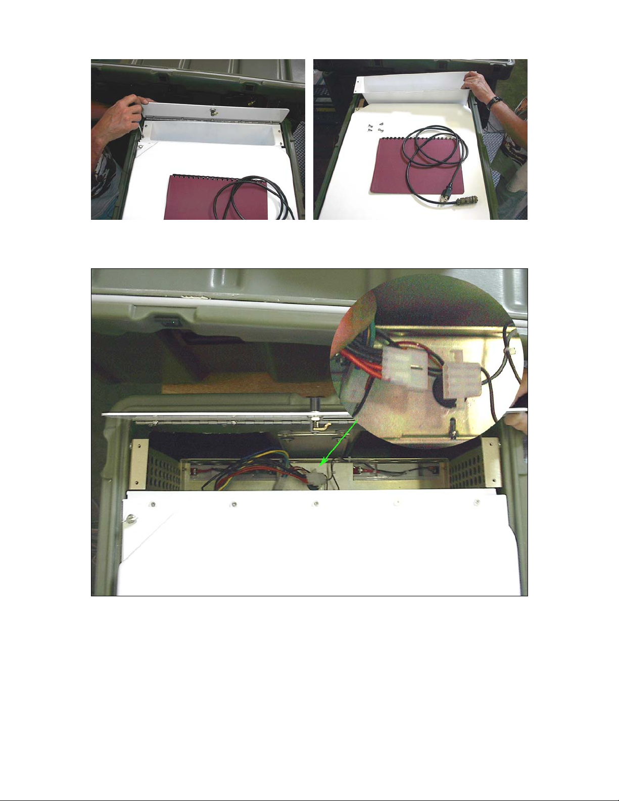
2. Remove the contents (lower half of Fig. 4).
3. Use the supplied screwdriver (or any #2 Phillips head screwdriver) to remove the
four corner screws that hold the compartment liner in place (Fig. 5).
4. Lift out the compartment liner (Fig. 6).
5. Inside are two sets of connectors. The square pair is already plugged in. The flat
pair connects the batteries. Plug the flat pair into each other (Fig. 7).
6. Replace the liner and the screws and close the lid. Return unused items to “Cable
and Manual Storage.”
Fig. 4. Cable and Manual Storage Compartment.
HEMACOOLTM Model HMC-MIL-1 Operations Manual August 2003
Energy Storage Technologies, Inc. Dayton, Ohio 45459
8
Fig. 5. Removing liner screws Fig. 6. Lifting out liner
Fig. 7. Battery connector

HEMACOOLTM Model HMC-MIL-1 Operations Manual August 2003
Energy Storage Technologies, Inc. Dayton, Ohio 45459
9
Control and Power Panel:
Prior to starting the unit, become familiar with the control and power panel. The panel is
located on the electronics compartment end of the machine (see right side of Fig. 1, page
4). It has two power input connectors (numbers 2and 3in Fig. 8).
The smaller connector (2) is for the AC power cord that arrives with the unit,
stored inside the Cable and Storage Compartment. The two fuses, 5a and 5b (see
Appendix C, Tools and Parts), are in line with this connector internally.
The larger connector (3) is either for a solar panel array or for employing one of
the optional power adapter cables used to run the unit from either 12 VDC or 24 VDC
external power.
Choose which external power source you intend to use during startup. Be certain
the necessary cables are available. The most common choice is to use the AC power cord
that comes with the machine.
Fig. 8. The control and power panel.
HEMACOOLTM Model HMC-MIL-1 Operations Manual August 2003
Energy Storage Technologies, Inc. Dayton, Ohio 45459
10
C. STARTING THE HemaCool™ :
CAUTION: Do not turn on the HemaCool™ until you have read the entire user’s
manual. Failure to understand the meaning of the LED readouts could result in loss
of stored blood, blood products, or medical supplies and possibly do damage to the
unit.
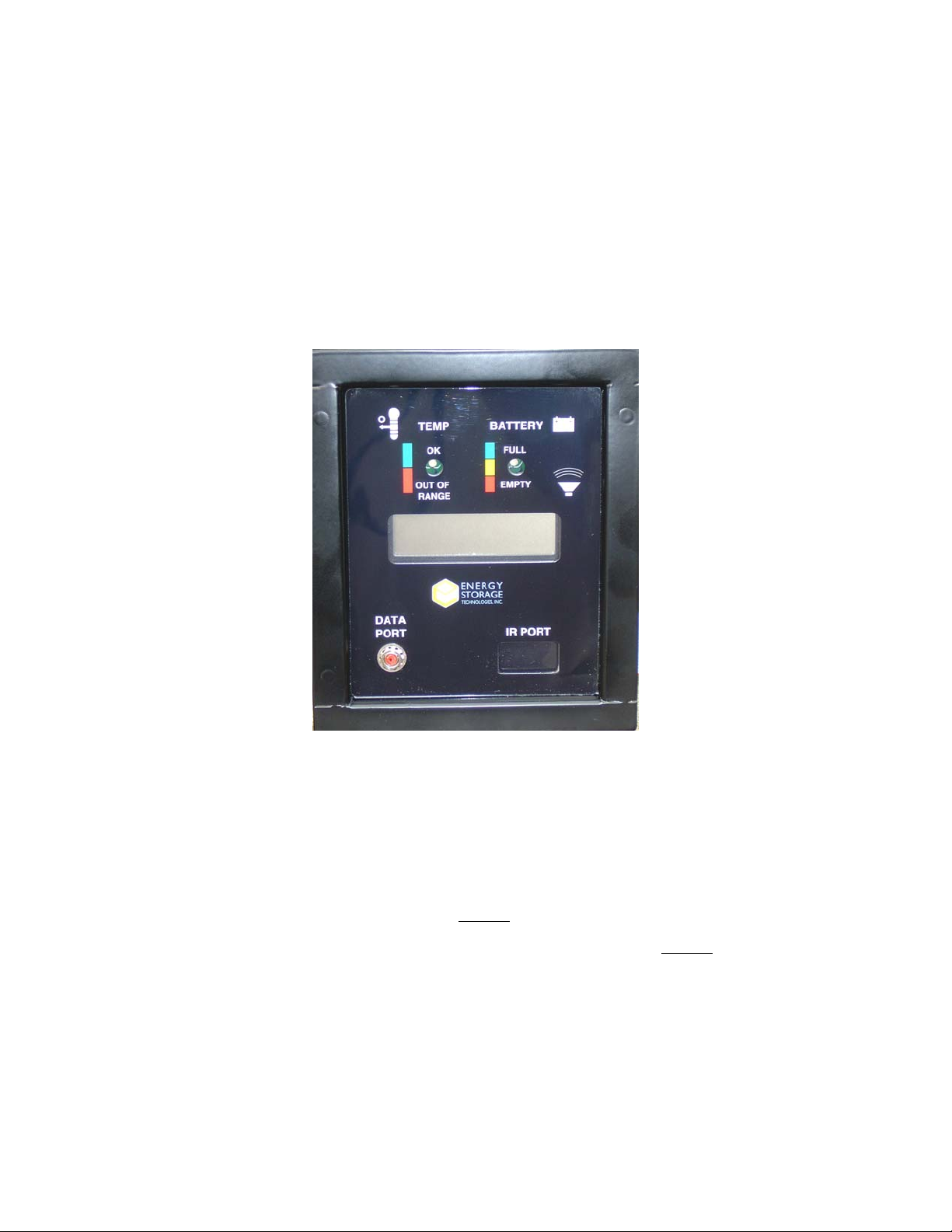
Fig. 9. HemaCool™ Display
1. Select the temperature you want to operate the unit with the toggle switch on the
power panel (Fig. 8 number 1).
The COOL (+4.0 ) control point is ONLY used for storing materials that must be
stored above freezing. The FREEZE (-22° C) control point is ONLY used for
materials to be stored frozen. (If the ambient temperature is more than +30°C
[+86°F], the device may not have the capacity to hold the payload at FREEZE
temperature below -20°C [-4°F]. See specifications at the end of this document.)

HEMACOOLTM Model HMC-MIL-1 Operations Manual August 2003
Energy Storage Technologies, Inc. Dayton, Ohio 45459
11
CAUTION: Selecting the wrong set point for your materials can damage or destroy
them. It is the end user’s responsibility to choose the control set point that matches the
temperature requirements of the payload. If in doubt, contact the manufacturer of the
materials to be stored for the temperature requirements so that the correct control set
point is selected. The set point selected is indicated on the LCD readout -- COOL or
FREEZE -- by the letters “c” or “f”, respectively, at the right end of the upper line
of the display (see HemaCool™ Display and Alarm Functions, below).
2. Pull out on the switch bat (handle) and flip it up for 4.0°C (39°F) control
setting, and down for –22°C (-7°F) operation (Fig. 8, number 1).
3. Attach the external source of power selected for the unit’s initial 24-hour cool-
down and stabilization period (connectors at Fig. 8, numbers 2and 3). Plug the
power source into the control and power panel (Fig. 8) on the electronics end of
the unit (right side Fig. 1).
CAUTION: Only AC power (and optional solar power) inputs charge the batteries.
Though engaged to the same connector as solar power, 12 VDC and 24 VDC
auxiliary power is applied through an isolated pin and does not charge the batteries.
It can, however, be used to assume the load of the 24-hour stabilizing period.
4. Press the ON/OFF button (Fig. 8 number 4). When operated from AC power,
the unit’s indicator lamps above and below the temperature selector (Fig. 8
number 1) will illuminate to show the unit is operating and at which temperature
setting. If you are operating on battery power, only the display panel lights will
come on. This is how you can be sure your AC power is connected and switched
on. Be sure the correct setting for your payload is indicated. The unit will now
run, and the bottom line of the display (Fig. 9) will read “STABILIZING 24hr”.

HEMACOOLTM Model HMC-MIL-1 Operations Manual August 2003
Energy Storage Technologies, Inc. Dayton, Ohio 45459
12
Stabilization:
CAUTION: The HemaCool™ must be started and allowed to operate for a 24-hour
stabilizing period before payload is put in place. This stabilizing period ensures that the
unit’s batteries are fully charged. Battery charge level is shown on the display (see
Display and Alarm Functions, below). Never begin a portable mission if the battery
voltage is below 14.2 volts.
Fig. 10. Diagram of display during 24 hr. stabilization period.
The temperature within the HemaCool™ will reach satisfactory levels for storing the
payload well before the twenty-four hour stabilizing period ends. However, the unit will
not achieve peak energy efficiency until 24 hours of continuous operation has been
completed.
During stabilization, the unit’s power demand will be above average. Therefore, it is
recommended that charging be done with an external power source during the first 24
hours, and any time batteries require charging.
Once this stabilization time is completed, the unit may be disconnected from the cabled
power source. It is then portable and under internal battery operation. If the unit is

HEMACOOLTM Model HMC-MIL-1 Operations Manual August 2003
Energy Storage Technologies, Inc. Dayton, Ohio 45459
13
disconnected long enough for the payload space to reach ambient temperature the
stabilization period must be repeated.
Following the 24-hour stabilization, the bottom row of the LCD display will display a
high/low temperature history. These alternate at 10-second intervals between the
maximum and minimum temperatures that have occurred in the most recent 7-day period.
This display reports how many days previously the maximum and minimum temperature
occurred (to the nearest ½ day). The maximum length of the stored history is one week,
after which the data is purged and the record begins again. The schematic on page 12
shows how the information is displayed for the stabilization period (Fig. 10).
Solar Option:
If solar power is the only available power source, it is recommended the solar panel be
allowed to charge the batteries for at least four (4) days before pressing the ON/OFF
switch (Fig. 8 number 4) to start the unit.
Change of Mode:
The temperature control point may be changed during operation. This is done by re-
setting the toggle switch (Fig. 8 number 1). Care must be taken, however, not to damage
stored blood or blood products. If the temperature is changed during operation, the
HemaCool™ must be allowed to equilibrate to the new temperature set point before it is
used to store or transport materials at the new temperature.

HEMACOOLTM Model HMC-MIL-1 Operations Manual August 2003
Energy Storage Technologies, Inc. Dayton, Ohio 45459
D. HemaCool™ DISPLAY AND ALARM FUNCTIONS:
Information on the status of the HemaCool™ is presented on a display panel (Fig. 10),
which employs two light emitting diodes [LED] and a liquid crystal display (LCD) that
includes two rows of text.
LEDs:
Two multicolored LED indicators provide temperature and battery status alarms. The
temperature LED – on the left – shows GREEN when the temperature is in the selected
range and RED when it is outside that range. In COOL mode it will also turn YELLOW
when the unit is switching between compressor and heater operation. This happens if the
ambient temperature has crossed over to the other side of the control temperature. The
battery status LED – on the right – shows GREEN when the battery has 10% or more of
charge, YELLOW when it has less than 10% of charge, and RED when the charge is
nearly gone. (When the unit is operated on AC power, the battery status [right LED]
should always illuminate GREEN or change to GREEN within a few minutes as the
internal battery recharges).
The tables below show the exact temperatures and voltages that trigger the LED color
changes for different set points:
Temperature LED Indictors: Temperatures for COOL mode
LED COLOR PAYLOAD SPACE TEMPERATURE
GREEN Between 1.0°C and 6.0°C (Between
34°F and 43°F)
YELLOW Unit is transitioning from compressor
to heater operation or vice versa.
RED 1°C and Below (34°F and Below)

HEMACOOLTM Model HMC-MIL-1 Operations Manual August 2003
Energy Storage Technologies, Inc. Dayton, Ohio 45459
15
Temperature LED Indicators: Temperatures for FREEZE mode
LED COLOR PAYLOAD SPACE TEMPERATURE
GREEN Below –20°C (Below -4°F)
RED -20°C and Above (-4°F and Above)
Battery Voltage LED Indicators:
LED COLOR BATTERY VOLTAGE
GREEN 11.8V and Above
YELLOW Between 11.5V and 11.8V
RED 11.5V and Below
Audible Alarm:
HemaCool™ mil version has an audible alarm that sounds only when the unit is
operating on AC power and a RED alarm condition occurs – that is, when temperature or
battery voltage is outside its nominal operating range. The alarm sounds three times at
one-second intervals in a cycle that recurs every eighteen seconds. The alarm indicates
that the payload is in danger and immediate attention is required. Typically, this means
attaching a different applicable/available power source to maintain unit operation while
simultaneously charging its internal batteries.
LCD Display:
The LCD display includes two rows of text. Reading from left to right, the top row
shows:
Payload temperature -- from -30.0°C to +50.0°C (from -22°F to 122°F)
Operating voltage

HEMACOOLTM Model HMC-MIL-1 Operations Manual August 2003
Energy Storage Technologies, Inc. Dayton, Ohio 45459
16
Compressor or heater status – whether the compressor or heater is operating
And:
oIf the compressor is operating an asterisk appears immediately following the
voltage readout.
oIf the heater is operating, a lower case “h” appears immediately following the
voltage readout. [Regardless of ambient temperature, the heater never operates if
the unit is being used as a freezer.]
oThe last character in the top row will be either a “c” to indicate COOL mode
(4.0°C [39°F] setting) or an “f” to indicate FREEZE mode (-22°C [-7°F])
setting).
Reading from left to right, the bottom row of text alternates each 10 seconds between:
•The Minimum or Maximum temperature measured in the payload compartment
within the past week
•How long ago (in days) since that temperature was last measured.
And:
•During the first 24 hours of operation, the bottom row of the LCD display will
read “STABILIZING 24hr” to indicate that the HemaCool™ has not achieved
full operating stabilization.

HEMACOOLTM Model HMC-MIL-1 Operations Manual August 2003
Energy Storage Technologies, Inc. Dayton, Ohio 45459
17
E. DATA LOGGER AND POCKET PC DOWNLOAD:
The unit is equipped with a data logging system. This system monitors the payload
temperature, the ambient temperature, and the HemaCool™ main battery voltage. The
data log may be downloaded by IrDA link into a Pocket PC (PPC) computer employing
the Windows CE operating system. This produces a text file that may be imported into a
spreadsheet program for graphing. The data logging system records a data point every
five minutes for up to 37 days. The logger is powered by a AA size lithium battery with
an operating life expectancy of 10 years.
Preparing Your Pocket PC
Use ActiveSync to place a copy of HemaLog.exe in the \Windows\Start Menu folder of
the PPC. This is accomplished by opening ActiveSync with the PPC in its cradle,
clicking down to the Start menu, opening that, then dragging HemaLog.exe into it from
the HemaLog™ Software CD.
After you start the HemaLog™ program on your PPC you will see:
The main screen:
Center: HemaLog Data Acquisition Tool
Bottom: Two menus, Access and Display.
Access menu includes:
Initialize/start collection - sets up the logger and starts data collection
(also needed after battery change).
Check battery condition - reports percent battery is charged.
Download data - brings logged data into PPC.
Download and re-start - brings logged data into PPC, clears logger
memory and resumes data collection.

HEMACOOLTM Model HMC-MIL-1 Operations Manual August 2003
Energy Storage Technologies, Inc. Dayton, Ohio 45459
18
Display menu includes:
List data - shows time and temperature data in tabular form.
Graph data - shows data vs. time in graphic form (some
versions require a separate graphing program).
About - shows company logo, copyright, name, and
contact information.
Each menu item has its own page and a plain text explanation, a start button and a
message window (except About), and an OK button to return to the main page.
The downloaded data files are ordinary text files suitable for import into Excel after they
have been copied into a PC using ActivSync. Each file is named using its logger’s ID
number with “.txt” appended. They are stored in a directory called \HemaLog on the
PPC. If you make a second download from the same unit into your PPC without first
deleting the old download file, the new data, including a new header, will be appended to
the end of the old file. This is to prevent accidental deletion of data. However, to graph
this appended data in Excel or other spreadsheet program, you will need to separate the
new data by scrolling down to its header, then selecting and copying it into a new
worksheet. To avoid lengthy data files, it is recommended you import the files to a PC
for permanent record keeping, then delete them from the PPC
Accessing the data logger memory:
Use your PPC stylus to depress the red button labeled “Data Port” on the display panel
(Fig. 9, page 10). This stops data logging and readies the logger for IR port
communication. Wait five seconds, then align the IR port of your PPC with the IR
window in the lower right corner of the display (Fig. 11), and then select the Access
menu. From there, select one of the two download functions in the submenu. Download
and re-start is most often used, as it retrieves the data and clears the logger memory for

HEMACOOLTM Model HMC-MIL-1 Operations Manual August 2003
Energy Storage Technologies, Inc. Dayton, Ohio 45459
19
new data. Download and stop downloads data, but leaves the collected data in the
logger’s memory. The message window at the bottom shows the data block count
incrementing during download.
You must use the Initialize/start collection function to start collecting data after the
Download data function has been used. The Download and re-start function does both
of these things in one step. After accumulating data for 37 days, the logger’s memory
will be full. If this happens, the logger continues collecting data by overwriting the
oldest data with new data points.
Once data has been retrieved, the software organizes it into a text file. This file is placed
in the \HemaLog folder in the PPC. Be certain to note the logger unit ID Number for
your refrigerator when you download and save data. This number is not the same as the
unit serial number. The two are kept different to prevent confusion if a repaired
HemaCool™ gets a different logger. From left to right, the columns of data in this file
show:
Time
Payload Temperature
Ambient Temperature
HemaCool™ battery voltage
A new row with all this information is added for each five-minute data collection event
during the logger’s operating period. This file may be transferred to your PC by the
ActiveSync program for later use.
Viewing Data
After retrieving data, press the OK button to return to the main screen. From there, select
the Display menu to view the data. Select the List data function to see the data in tabular
Table of contents
Popular Freezer manuals by other brands

Polar Electro
Polar Electro DB319-A instruction manual

Frigidaire
Frigidaire FFU0912DW1 Service data sheet

Fagor
Fagor FCC100M instruction manual

Delfield
Delfield Meridian MFR1-S Specifications

Nordcap
Nordcap SKF 5 GN 1/1 PLUS Montage and Installation

AGA marvel
AGA marvel MS15FA Installation, operation and maintanance instructions


