ENERGY SUPPORT CORPORATION DTF-102 User manual

Instruction Manual
DTF-102 Receiver
Type:DTF-102
No.-3243E R2
【Product】
・ DTF-102 Receiver :KX-621038-XXXXXX


I
Preface
This manual is written for those who handle DTF-102 type receiver. Be sure to read this manual before
using the product to ensure proper and safe operation of the product.
In particular, be sure to read "For Your Safety" and use the product correctly. And keep it in a place
where anyone using this product can view it at any time.
The contents of this manual are subject to change without notice for improvement.
Please refer to the latest instruction manual when using.
If you find any unclear points, errors, omissions, etc. regarding the contents of this manual, please
contact us or our distributors.
Product Applications
Consult with us in advance regarding use for the following purposes.
Radiation-related equipment
Nuclear applications
Medical use
Uses that have a large impact on important property or rights
Other uses related to life and body
Scope of Liability and Warranty
[ Warranty Period ]
1 year after delivery
*If a separate warranty period is stipulated in a document such as a delivery specification, the
contract shall take precedence.
[ Warranty Conditions ]
During the warranty period, if a failure occurs due to our responsibility, we will provide a substitute or
replacement part or repair the delivered product free of charge.
However, the following cases are not covered by the warranty.
*If a separate warranty period is stipulated in a document such as a delivery specification, the
contract shall take precedence.
When used in environments other than those specified in this manual
Failure to follow the instructions in this manual or use in a manner other than that described in this
manual
In case of failure due to incorrect operation
If the product is repaired, processed, remodeled, or disassembled by anyone other than us or
someone authorized by us
When used in combination with parts other than our company
In the event of a disaster beyond our responsibility, such as a natural disaster
In case of damage, breakage, or failure due to dropping or transportation after purchase
Failure due to corrosion, rust, etc. Deterioration of appearance.
Consumable parts

II
[Warranty Scope]
The scope of warranty is limited to our products.
Regardless of the warranty period, our company does not take any responsibility for the following.
Indirect damage due to failure of our products or unforeseen defects by our company (Loss of profit,
opportunity loss, compensation for damage or failure to products other than those supplied by us,
compensation for other operations, compensation for accidents, etc.).

III
About This Instruction Manual
Deliver this manual to the final user.
The contents of this manual are subject to change without notice for improvement.
Unauthorized reproduction or duplication of part or all of the contents of this manual is strictly
prohibited.
If you find any unclear points, errors, omissions, etc. regarding the contents of this manual, please
contact us or our distributors.
About Related document
Related documents are below.
TF-10 Type Probe Transmitter Instruction Manual No.-3071-*
TF-Ⅲ Type Probe Transmitter Instruction Manual No.-3064-*, 3144-*, 3231-*, 3223-*
TF-Ⅳ Type Probe Transmitter Instruction Manual No.-3066-*, 3068-*
Description in This Manual
Notation of the Figure
The figures in this manual may be emphasized, simplified, or partially omitted for convenience of
explanation. Pictures such as screens may differ from the actual display. In addition, the contents
described may be "display examples".
Trademarks
Company names and brand names are either registered trademarks or trademarks of the respective
companies. (R), (TM) symbols may be omitted in this manual.
Original language
This is the English translation of an original Japanese document.
Disposal of the Product
When disposing of the product, comply with local regulations.
This interprets the necessary points for correct operation and notifies the important points for
handling the product.
Note
This indicates the part where to refer for information.
Refer
This indicates reference information.
Tip

IV
For Your Safety
Warning messages given here are for safe and correct use of the product and for prevention of harm or
damage. These are important safety note, so be sure to read it carefully before use and be sure to
observe it.
The meanings of the symbols are as follows.
DANGER This indicates an imminently hazardous situation which,
if not avoided, will result in death or serious injury.
This is to be limited to the most extreme situations.
WARNING This indicates a potentially hazardous situation which,
if not avoided, could result in death or serious injury.
CAUTION This indicates a potentially hazardous situation which,
if not avoided, may result in minor or moderate injury.
It may also be used to alert against unsafe practices.

V
When deciding on the "Installation Location"
DANGER
Explosion or Fire
This product is not explosion-proof. Do not use in an explosive gas
atmosphere.
When using a standard gas cylinder, install or store the standard gas
cylinder in a location with an ambient temperature of 40°C or less and
out of direct sunlight.
CAUTION
Injury, Malfunction or Damage
Install in a location that satisfies the installation location conditions
described in "Table 3-1 Installation location".
When "Installing" or "Transporting"
CAUTION
Fall, Damage or Injury
Installation work correctly according to the instruction manual.
Tighten screws with the appropriate tightening torque. Insufficient
tightening may cause damage or drop. Also, if it is tightened too much, it
may not be possible to remove it.
When "Wiring"
WARNING
Fire, Electric shocks, Malfunction
Wiring work should be done by a person with appropriate technical
training and experience.
Use the power supply at the rated voltage.
Be sure to turn OFF the main power supply before performing wiring
connection work or wiring check.
Connect grounding.
Do not apply an excessive load to the cables and cord, such as bending
and stretching them repeatedly, putting a heavy thing on them.
Use appropriate wiring material according to the rating of the device.
VI
When "Starting measurement" or "Maintenance work"
WARNING
Fire, Electric shocks, Malfunction
Be sure to turn OFF the main power supply before performing wiring
connection work or wiring check.
Before turning ON the power, make sure that the power wiring is
properly connected.
If the fuse blows, check the cause and replace it with one of the same
capacity and type. Also, when replacing the fuse, be sure to turn OFF
the main power supply before starting work.
Be sure to use parts specified by our company for replacement parts
and consumables.
Other
CAUTION
Fire, Electric shocks, Injury or Damage
In the event of a failure that cannot be determined by looking at the
instruction manual, be sure to contact our company or the agency
where you purchased the product, and request repairs if necessary.

VII
Product Handling Information
If this product is used in a manner not specified by us, it may impair the protective functions and
performance provided by this product. It is strictly prohibited to modify the product by the customer.
Observe the following precautions.
General
Use in a manner not specified in this manual may impair the protection provided by this product.
Do not disassemble the parts other than those specified in this manual.
Do not modify by the customer.
Do not use accessories other than this product.
Even if the temperature is within the range of the ambient temperature specification of this product,
the life of the product may be shortened if it is used in a constantly high ambient temperature
environment.
This product is intended for industrial environments. In a domestic environment this product may
cause radio interference in which case the user may be required to take adequate measures.
Precautions during construction
Install the product in a location where the required space can be secured. If space is not secured,
daily inspections and maintenance will not be possible, leading to equipment stoppages and
product damage.
Notes on settings
When using the product for the first time or after replacing the sensor, always setting the sensor
parameters to receiver. The parameter settings to be used, see the inspection report.

VIII

Table of Contents
1
Type:DTF-102
Product Name:DTF-102 Receiver
Table of Contents
Preface .................................................................................................................. I
For Your Safety .................................................................................................. IV
Product Handling Information.......................................................................... VII
1 Overview ......................................................................................................... 5
1.1 About This Product ................................................................................................................ 5
1.2 Products and Accessories ..................................................................................................... 5
1.3 Temporary Storage ............................................................................................................... 5
2 Part Names ...................................................................................................... 6
2.1 Receiver ................................................................................................................................ 6
3 Installation ...................................................................................................... 8
3.1 System Configuration Example ............................................................................................. 8
3.1.1 System Configuration Example 1 ................................................................................................... 8
3.1.2 System Configuration Example 2 ................................................................................................... 9
3.1.3 System Configuration Example 3 ................................................................................................... 9
3.2 Place Conditions for Installation .......................................................................................... 10
3.3 Installing the Receiver ......................................................................................................... 11
3.3.1 Panel Mount ................................................................................................................................. 11
3.3.2 Wall Mount ................................................................................................................................... 11
3.3.3 Stand Mount ................................................................................................................................ 12
3.4 Connecting Wires ................................................................................................................ 13
3.4.1 Connecting to Terminal Block ....................................................................................................... 13
3.4.2 Wiring Connection Example ......................................................................................................... 14
3.4.3 Wiring Method When Replacing from DTF-101 Receiver .............................................................. 15
3.4.4 Wiring Confirmation Sheet When Replacing from DTF-101 Receiver ........................................... 16
4 Measurements .............................................................................................. 19
4.1 Necessary Steps before Starting ......................................................................................... 19
4.1.1 Setting Items of Sensor Parameters ............................................................................................. 19
4.2 Starting and Stopping Measurement ................................................................................... 20
4.3 Key Operation ..................................................................................................................... 21
4.3.1 Explanation of Keys ..................................................................................................................... 21
4.3.2 Display Transition ........................................................................................................................ 22
4.3.3 Display by Operating State ........................................................................................................... 23
4.3.4 Data Settings Overview ................................................................................................................ 24
4.3.5 Data Setting/Checking Method ..................................................................................................... 24

Table of Contents
2
5 Calibration ..................................................................................................... 25
5.1 About Calibration ................................................................................................................ 25
5.2 Calibration Point and Calibration Type ................................................................................ 25
5.2.1 Calibration Point Type ................................................................................................................. 25
5.2.2 Calibration method Type .............................................................................................................. 26
5.3 Manual Calibration .............................................................................................................. 27
5.3.1 Manual Calibration (Air Point) ...................................................................................................... 27
5.3.2 Manual Calibration (Air Point & Other Points) .............................................................................. 28
5.4 Semi Auto / Auto Calibration ............................................................................................... 30
5.4.1 Semi Auto / Auto Calibration (Air Point) - advance setting – ......................................................... 30
5.4.2 Semi Auto Calibration (Air-Point) - Key Operation or Contact Input - ............................................ 31
5.4.3 Auto Calibration (Air-point)........................................................................................................... 32
5.4.4 Semi Auto/Auto Calibration (Air Point & Other Points) - advance setting - .................................... 33
5.4.5 Semi Auto Calibration (Air Point & Other Points) - Key Operation or Contact Input - ..... 34
5.4.6 Auto Calibration (Air Point & Other Points) ................................................................................... 35
5.4.7 Calibration Stop Operation ........................................................................................................... 35
6 Purging .......................................................................................................... 36
6.1 About Purging ..................................................................................................................... 36
6.2 Purge Method Type ............................................................................................................. 36
6.3 Semi Auto Purge / Auto Purge ............................................................................................ 37
6.3.1 Semi Auto Purge / Auto Purge - advance setting - ....................................................................... 37
6.3.2 Semi Auto Purge - Key Operation or Contact Input - .................................................................... 38
6.3.3 Auto Purge .................................................................................................................................. 39
6.3.4 Purge Stop Operation .................................................................................................................. 39
6.4 Reset of Cycle Timer and Countdown ................................................................................. 40
6.4.1 Reset Method of Cycle Timer ....................................................................................................... 40
6.4.2 Cycle Timer Countdown ............................................................................................................... 41
7 Other Settings/Functions.............................................................................. 42
7.1 Analog Output ..................................................................................................................... 42
7.1.1 Analog Output Specifications ....................................................................................................... 42
7.1.2 Setting, Checking and Switching of Output Range ....................................................................... 42
7.1.3 Output Hold Function ................................................................................................................... 43
7.1.4 Simulated Output ......................................................................................................................... 44
7.1.5 Adjustment of Analog Output ....................................................................................................... 44
7.2 Contact Output .................................................................................................................... 45
7.2.1 Contact Outputs Specifications .................................................................................................... 45
7.2.2 Contact Outputs Items and Setting .............................................................................................. 45
7.3 Contact Input....................................................................................................................... 48
7.3.1 Contact Inputs Specifications ....................................................................................................... 48
7.3.2 Contact Inputs Items .................................................................................................................... 48
7.4 Sleep Mode ......................................................................................................................... 49
7.4.1 About Sleep Mode ....................................................................................................................... 49
7.4.2 Switch to Sleep Mode and Operation ........................................................................................... 49

Table of Contents
3
7.5 Other Functions ................................................................................................................... 50
7.5.1 Concentration Upper / Lower Alarm (Alarm H, Alarm L, Alarm H&L) ............................................. 50
7.5.2 Primary Delay Calculation Function .............................................................................................. 50
7.5.3 Moving Average Function ............................................................................................................. 50
7.5.4 Protection Function of Set Value .................................................................................................. 50
7.6 CH Data Table .................................................................................................................... 51
8 Maintenance .................................................................................................. 54
8.1 Daily / Periodic Inspection ................................................................................................... 54
8.2 Consumable Parts and Spare Parts .................................................................................... 54
9 Troubleshooting ........................................................................................... 55
9.1 Phenomena and Countermeasures ..................................................................................... 55
9.2 Error Code Table ................................................................................................................. 56
9.2.1 Oxygen Sensor Failed .................................................................................................................. 57
10 Technical Data .............................................................................................. 58
10.1 Specifications ...................................................................................................................... 58

Table of Contents
4

1 Overview
5
1 Overview
1.1 About This Product
This product is a control device that drives and controls the oxygen sensor in an oxygen analyzer that
uses a limiting current type zirconia oxygen sensor, and is responsible for concentration calculation
and output. It is used in combination with our oxygen sensor (transmitter).
Since the oxygen sensor of this analyzer does not require pretreatment of the measurement gas, it is
smaller and has a faster response speed than conventional sampling-type devices equipped with a
pretreatment device.
In addition, since calibration can be performed using only "instrumentation air" using compressed air,
which is commonly found in factories and ships, there is the advantage of not needing to install or
manage standard gas cylinders.
1.2 Products and Accessories
When you receive the product, open the package and check for any shipping damage.
Also, make sure that the delivered items and accessories are correct.
Table 1-1 Supply Parts List (one set)
Name No. Q'ty Remarks
Receiver KX-621038-XXXXXX 1
If Receiver is delivered in a unit case or mounted on an independent panel, refer to the supply parts list
of the delivery specifications.
Table 1-2 Option Parts List
Name No. Q'ty Remarks
Stand mounting bracket
KS-224193 1 For detail, see "3.3.3 Stand Mount".
1.3 Temporary Storage
When storing the product temporarily prior to installation, observe the following conditions.
Away from direct sunlight.
The ambient temperature is between -10℃ and 50℃, with little variation in temperature.
There is little humidity and dust.
The location is not exposed to rainfall.
There is little mechanical vibration.
There are no corrosive gases or dangerous gases.

2 Part Names
6
2 Part Names
2.1 Receiver
【Dimensions】
Front view
Bracket 1
Bracket 2
Right side view
Bottom view
Wiring hole 7-Φ27
With grommets
250 Knurled fastener
Door
Window
300
270
200
*Dimensional tolerances without individual tolerance indications are according to JEM 1459.
156
135
Mounting hole Φ10

2 Part Names
7
【Inside】
Display panel
(For detail, see below fig.)
Door
【
Display Panel
】
Terminal block
Power switch
Fuse
Power lamp
Lights when the power is on.
Operation key
Used for setting sensor parameters,
changing/checking various settings,
and releasing errors.
Display 1
"Oxygen concentration", "Setting data",
"Error code" and "Countdown" are displayed.
Display 2
"Output range", "CH No.", "States of Analyzer",
"Concentration upper limit alarm", "Concentration
lower limit alarm" are displayed.
%
lamp
Lights when the concentration
unit is %.
ppm lamp
Lights when the concentration unit
is ppm.
Display panel
3 Installation
8
3 Installation
This product is a device that controls Oxygen Sensor and calculates and outputs concentration.
In order to measure the oxygen concentration, connect our company's zirconia Oxygen Sensor and
use it by constructing piping related parts. A typical system configuration example is shown below.
3.1 System Configuration Example
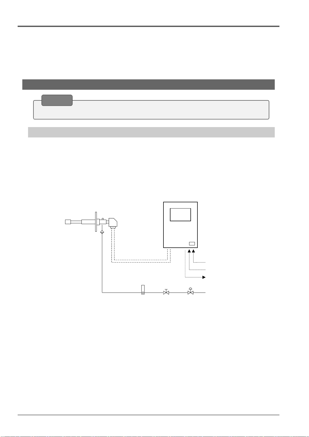
3.1.1 System Configuration Example 1
This system is an example of using "TF-10 Probe Transmitter" as an oxygen sensor to measure the
oxygen concentration in flue gas from a boiler, etc. Manually operated valves such as needle valve and
ball valve are used for calibration gas lines. At the time of calibration, after manually operating the
valve to supply the calibration gas, calibration is executed by key operation on the receiver.
Use instrument air or atmospheric gas for calibration. (Calibration using standard gas cylinders such
as zero gas and span gas is not required.)
Confirm the delivery specifications for scope of delivery and actual system configuration.
Note
TF-10 Probe Transmitter
DTF-102 Receiver
Power supply 100 to 240 VAC
Contact input
Analog output (DC4 to 20mA)
Contact output
Flow
meter
Needle
valve
Pressure
reducing valve
Check valve
Control/signal wires
for sensor
4 cores shielded×2
Calibration gas
(Instrument air or atmospheric gas)
Fig. 3-1 System Configuration Example 1
3 Installation
9
3.1.2 System Configuration Example 2
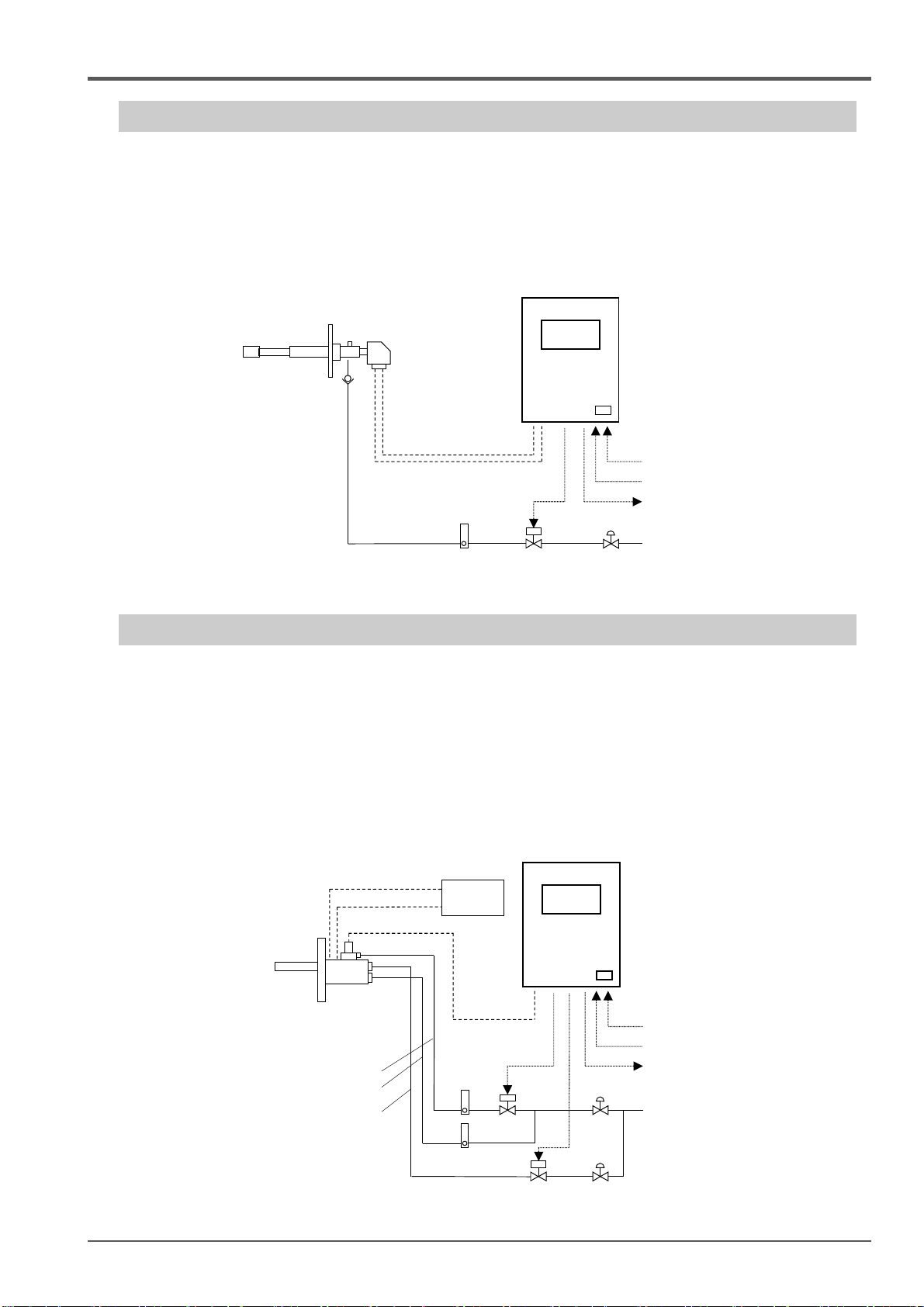
This system is an example of using "TF-10 Probe Transmitter" as an oxygen sensor to measure the
oxygen concentration in flue gas from a boiler, etc. A solenoid valve is installed in the calibration gas
line, and the contact output of the receiver is used to open and close the solenoid valve. Calibration
can be performed by methods such as "receiver key operation", "contact input", and "receiver internal
timer". Use instrument air or atmospheric gas for calibration. (Calibration using standard gas
cylinders such as zero gas and span gas is not required.)
3.1.3 System Configuration Example 3
This system uses a TF-III type probe transmitter as an oxygen sensor, to measure the oxygen
concentration in high-temperature flue gas in a heating furnace. In addition to calibration gas piping,
ejector air piping and purge air piping are used. Since the calibration gas and purge air are operated by
opening and closing the solenoid valve using the contact output of the receiver, calibration and purge
can be performed by methods such as "receiver key operation", "contact input", and "receiver internal
timer". Use instrument air gas for calibration. (Calibration using standard gas cylinders such as zero
gas and span gas is not required.) The TF-III type probe transmitter uses a separate power supply
and temperature control device for heating and keeping warm in order to prevent dew condensation in
the sampling section.
DTF-102 Receiver
K thermocouple
compensating lead
Heater power
Fig. 3-3 System Configuration Example 3
Fig. 3-2 System Configuration Example 2
TF-10 Probe Transmitter
Check valve
Control/signal wires
for sensor
4 cores shielded×2
Power supply 100 to 240 VAC
Contact input
Analog output (DC4 to 20mA)
Contact output
Flow
meter
Solenoid
valve
Pressure
reducing valve
Calibration gas
(Instrument air or atmospheric gas)
Contact output
Power supply 100 to 240 VAC
Contact input
Analog output (DC4 to 20mA)
Contact output
Flow
meter
Solenoid
valve
Pressure
reducing valve
Contact output
Instrument air
Control/signal wires
for sensor
8 cores shielded×1
TF-Ⅲ Probe Transmitter
Temperature
control device
Calibration gas piping
Ejector air piping
Purge air piping
DTF-102 Receiver

3 Installation
10
3.2 Place Conditions for Installation
When deciding on the "Installation Location"
DANGER
Explosion or Fire
This product is not explosion-proof. Do not use in an explosive gas
atmosphere.
When using a standard gas cylinder, install or store the standard gas
cylinder in a location with an ambient temperature of 40°C or less and
out of direct sunlight.
CAUTION
Injury, Malfunction or Damage
Install in a location that satisfies the installation location conditions
described in "Table 3-1 Installation location".
For safe, correct use of your oxygen analyzer, install the analyzer in a location with the following
conditions to provide the best possible installation conditions.
Not caused condensation by sudden temperature fluctuations.
Not directly exposed to much radiated heat.
Not significantly affected by electromagnetic fields.
Not exposed to much moisture and/or dust.
Little voltage fluctuation.
Little power frequency fluctuation.
Meeting the following conditions "Table 3-1 Installation Conditions":
Table 3-1 Installation Conditions
Item Spec.
Installation location Indoor
Ambient temperature -10℃ to +50℃
Ambient humidity 90%RH or less (Not condensation)
Environmental protection No waterproof structure
For the installation location conditions of the oxygen sensor (transmitter), check the instruction manual
of the oxygen sensor (transmitter) to be used.
Even if the temperature is within the range of the ambient temperature specification of this product,
the life of the product may be shortened if it is used in a constantly high ambient temperature
environment.
Install the product in a location where the required space can be secured. If space is not secured,
daily inspections and maintenance will not be possible, leading to equipment stoppages and product
damage.
This product is intended for industrial environments. In a domestic environment this product may
cause radio interference in which case the user may be required to take adequate measures.
Note
Popular Receiver manuals by other brands


Harman Kardon
Harman Kardon DPR 1005 Service manual

Explo IGNsystems GmbH
Explo IGNsystems GmbH RX2-1K Gas manual

Sony
Sony SAT-A2 Operating Instructions (primary... operating instructions

Harman Kardon
Harman Kardon HK3475 Product View

Extron electronics
Extron electronics FOXBOX Tx HDMI user guide

EasyDAB
EasyDAB V-DAB+ user manual


