Fortress Technologies am Gard S40 User manual

Description
S40IR Escape Release Adaptor module is used in conjunction with a releasing
amGardS40 unit, to provide an escape function from an interlocked hazardous
area. There are three versions, one with a key reset, one with a push button
reset and one with a simple pull reset. The other option is the length of plunger
needed to clear the door post thickness. This unit must always be mounted as
the rst module under the head.
Note: Releasing versions of other modules are the type that MUST be used in
conjunction with this module. This module MUST be mounted directly below the
head module.
Options &
Ordering Information
Description Post Thickness Part No.
Key Reset 60mm S40R2
Key Reset 80mm S40R3
Key Reset Variable* S40R4
Pull Reset 60mm S40R7
Pull Reset 80mm S40R8
Pull Reset Variable* S40R9
Front Reset (no key) 60mm S40RX
Front Reset (no key) 80mm S40RY
Front Reset (no key) Variable* S40RZ
*Suitable for increased post thicknesses up to a maximum of 350mm. For any greater post thickness additional support may be required, contact your
Fortress representative.
Important:
This product is designed for use according to the installation and operating instructions enclosed. It must be installed
by competent and qualied personnel who have read and understood the whole of this document prior to commencing
installation. If the equipment is used in a manner not specied by the manufacturer, the protection provided by the equipment
may be impaired. Any modication to or deviation from these instructions invalidates all warranties. Fortress Interlocks Ltd
accepts no liability whatsoever for any situation arising from misuse or misapplication of this product.
Note: The availability of spare Actuators and Keys makes it possible to easily bypass the safety devices and, for
this reason, the security of any spare Actuators and Keys must be effectively monitored.
DO NOT LEAVE OVERRIDE/RESET KEY IN PLACE!
Always keep it in a secure place, under management control, as it allows access to areas that may have a residual
hazard,and may result in incorrect operation of some devices.
BEWARE OF INTENTIONAL MISUSE CAUSED BY OPERATORS WANTING TO BYPASS SAFETY SYSTEMS. THE
INSTALLER SHOULD ASSESS THE RISKS AND MITIGATE AGAINST THEM.
Safety switches (such as a Stop or LOK) must be tted in conjunction with this unit to monitor when the Escape
Release has been activated. When lock adaptors are also used it is not possible to change a Stop to a LOK (and
vice versa) without other changes to the locks - seek advice from Fortress.
IF YOU HAVE ANY QUESTIONS OR QUERIES OF ANY NATURE WHATSOEVER PLEASE CONTACT THE SUPPLIER
WHO WILL BE PLEASED TO ADVISE AND ASSIST.
Adaptors
Gard
S40
Operating Instructions: S40 IR - Escape Release Adaptor
1

amGardS40 IR Technical Specication
Housing Materials Stainless Steel to BS3146 (ANC4B)
Internals All Stainless Steel
Mechanical Life 1,000.000
Vibration Tested in accordance with: GS-ET-19
Performance Level PLe
B10d 5,000,000
Ambient Temperature -20°C to 80°C (-4°F to 176°F)*
Max. Altitude 2000m
Maximum Relative Humidity 80%@<=31°C; 50%@40°C
Environment Indoor & Outdoor
*The units will only continue to work below freezing point (0°C) where it can be guaranteed that ice will not form on or in the unit; as it will cause the
mechanical parts to bind and jam.
amGardS40 IR - Safety Functions Part No.
Safety Function 1 Transmit movement (for locking & contact break purposes) when
escape not used. S40R2/3/4 S40R7/8/9 S40RX/Y/Z
Safety Function 2 Unlocks during escape release & transmits motion to safety
contacts.
2
Figure 1: Dimensional Drawing -
amGardS40 IR - Escape Release Adaptor
This unit ensures that safe escape can be made through the door, which will activate the safety switch circuits (when tted to
the appropriate host unit) regardless of the locking action of any solenoid or lock being tted.
• Only 1 S40 IR adaptor can be tted in a conguration.
• S40 IR Adaptor must be used in conjunction with ‘releasing’ type units in the amGardS40 range.
Operating Instructions: S40 IR - Escape Release Adaptor
M3 X 16 CAP HEAD
LID SCREWS
M4 X 30 CAP
HEAD SCREWS
RESET KEY
PLASTIC RUNNER
BAR SUPPORTS
PUSH INTERNAL
RELEASE MECHANISM
SHAKE PROOF
WASHERS
PUSH BUTTON

3
Figure 2: Dimensional Drawing -
Figure 3: Dimensional Drawing -
Operating Instructions: S40 IR - Escape Release Adaptor
2 OFF M8 X 15
(ACCESS FROM THE REAR)
PANEL THICKNESS
(SHOWN IN
UN-TRIGGERED STATE)
M8 THREADED ROD TO BE FIXED AT BOTH ENDS
WITH LOCTITE 243 THREADLOCKER OR EQUIVALENT
M8 THREADED ROD CAN BE CUT TO
SUIT DESIRED PANEL THICKNESS
2 OFF M8 X 15 HOLES
(ACCESS FROM THE REAR)
SECTION Z-Z
SECTION Y-Y 6 THRU HOLES
(4 PLACES)
S40R4 ONLY
S40R4, S40RZ ONLY
83 MAX
(338 REF.)
28
M8 THREADED ROD LENGTH = PANEL THICKNESS - 38mm
4
Figure 4: Dimensional Drawing -
Tools and Fixings Required
2.5mm A/F hex wrench (Torque Setting 0.8 - 1.0 Nm)
Ø8.2mm Drill
2 x M8 screws for xing S40 IR Adaptor. (Screws must be suitable length for a minimum of 10mm thread engagement with
Adaptor. Required screw type and class; A2 70. Required torque setting; 4-6 Nm.)
Ø36mm Drill
Required Torque Settings
If removed during mounting, re-orientation or electrical wiring, all supplied xing screws of the complete Guard Interlocking
Device must be retted using the following torque settings;
- M3 Screws – 0.8-1.0 Nm.
- M4 Screws – 2-4 Nm.
- M5 Screws – 2-4 Nm.
- M8 Screws (required for device mounting but not supplied) – 4-6 Nm.
Operating Instructions: S40 IR - Escape Release Adaptor
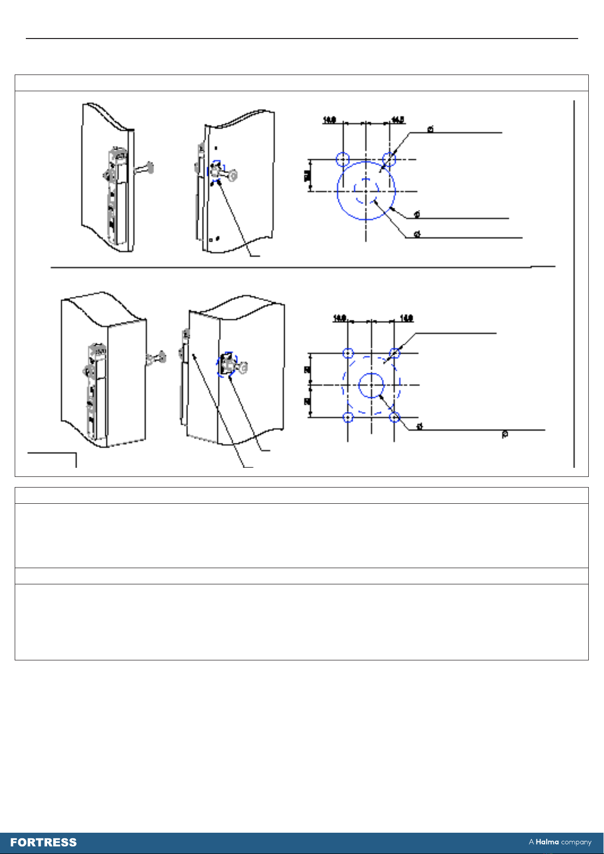
PANEL MOUNTING FOR S40R2, S40R3, S40R7,
S40R8, S40RX & S40RY TYPES
PANEL CUTOUT DETAIL A.
REQUIRED FOR ALL S40 IR ESCAPE RELEASE ADAPTORS.
2 x 8.5 CLEARANCE HOLES
TO SUIT M8 REAR FIXING
36. MINIMUM CLEARANCE HOLE
THROUGH FIRST 50mm OF PANNEL
15 MINIMUM CLEARANCE THRU HOLE
AFTER 50mm
PANEL CUTOUT DETAIL A
PANEL MOUNTING FOR S40R4, S40R9 & S40RZ TYPES
PANEL CUTOUT DETAIL B.
ADDITIONAL MACHINING REQUIRED FOR ALL VARIABLE LENGTH
S40 IR ESCAPE RELEASE ADAPTORS OR THOSE WITH EXTENSION KITS FITTED.
4 x M5 THREADED HOLES
15 MINIMUM CLEARANCE THRU HOLE
(MUST BE CONCENTRIC TO 36mm HOLE OF
PANEL CUTOUT DETAIL A)
PANEL CUTOUT DETAIL B
PANEL CUTOUT DETAIL A

5
Mounting
1. Locate the device so that inspection and replacement are possible.
2. M o u n t t h e e n c l o s u r e a s s e m b l y t o g e t h e r w i t h h e a d a s s e m b l y t o a a t m e t a l , s t a t i c p a r t o f t h e m a c h i n e . U s e M 8 s c r e w s
from the rear. The mounting surface should be at.
3. R e f e r t o p a n e l c u t o u t d r a w i n g ( g . 4 ) o n p a g e 6 f o r r e q u i r e d m a c h i n i n g a n d p r e p a r a t i o n o f m o u n t i n g s u r f a c e s b e f o r e
assembly.
3a. Minimum Ø36mm clearance hole must be cut in mounting surface to provide clearance for the internal pusher of
all S40IR Adaptor types. Refer to g.4 panel cutout drawing for further details.
3b. For all variable-length S40 IR Adaptor types (or for any S40 I R A d a p t o r w i t h a n e x t e n s i o n k i t t t e d ) a d d i t i o n a l m a c h i n i n g
is also required to mount internal pusher support – Refer to g.3 and g.4 for further details. Internal pusher support
must be secured using 4 x M5 screws.
3c. In all variable-length S40 IR Adaptor types (or for any S40 IR Adaptor with an extension kit tted) the length of
the supplied M8 threaded rod can be cut to suit increased post thickness of up to a maximum of 350mm.
For any greater post thickness additional support may be required, contact your Fortress representative.
4. Loctite 243 threadlocker (or equivalent) must be used after assembly to secure M8 threaded rod of all variable-length
S40IR Adaptor types (or for any S40 IR Adaptor with an extension kit tted) – see Fig.3 for more details.
5. Ret any lids to host units after cabling is completed.
6. A l l x i n g s c r e w s u s e d t o m o u n t t h e c o m p l e t e G u a r d L o c k i n g D e v i c e m u s t b e p e r m a n e n t l y p r e v e n t e d f r o m r e m o v a l , e i t h e r
by vibration or by personnel using standard tools. If mounting xings are visible, they must be secured against
m a n i p u l a t i o n a n d u n - a u t h o r i s e d o r u n - i d e n t i a b l e r e m o v a l . I n t h e s e c a s e s , a m i d d l e s t r e n g t h a d h e s i v e s c r e w l o c k e r i s
required.
7. The installation and operation of the complete Guard Interlocking Device must take into account the requirements of EN
ISO 14119; in particular Section 7 – Design for minimising defeat possibilities.
8. T h e c o m p l e t e G u a r d I n t e r l o c k i n g D e v i c e m u s t n o t b e u s e d a s a m e c h a n i c a l s t o p . W h e r e a p p l i c a b l e , p r e c a u t i o n s m u s t b e
made to ensure the door or gate of any guarded area has sufcient support and stops to prevent the impact on
the Guard Interlocking Device.
9. The complete Guard Interlocking Device must be mounted in the correctly assembled condition so that the Escape
Release action is only possible from within the guarded area (danger zone).
Testing
The complete guard installation should be tested prior to use.
Place the complete Guard Interlocking Device into its locked state so that the Safety Circuits of the accompanying Safety
Switch (S40 LOK or S40 Stop) are closed. Operate the Escape Release function by depressing the internal Push Button of
the S40 IR Adaptor. The Guard Device will now be in its unlocked state - check that the assembled Actuator can be removed
from the assembled Head and that the Safety Circuits of the accompanying Safety Switch (S40 LOK or S40 Stop) are now
open. Restoration of the protection is necessary before normal operation can be resumed.
To reset the Guard Device and return it to its locked state – rst close the guarded area by re-inserting the Actuator into the
Head unit, then reset the S40 IR Adaptor as per the following instructions.
• For Key-Reset versions (S40R2, S40R3 and S40R4), insert the Reset Key and rotate it 90 degrees clockwise before
pushing the Reset Push Button on the external lid assembly.
• For Keyless-Push-Reset versions (S40RX, S40RY and S40RZ), push the Reset Push Button on the external lid assembly.
• For internal Pull-Reset versions (S40R7, S40R8 and S40R9), pull on the internal Push Button fully.
After Reset, check that the Guard Device has returned to its locked state and that Safety Circuits of the accompanying Safety
Switch (S40 LOK or S40 Stop) are re-closed.
Warning: This device does not contain the Machine Reset or Restart facility after an escape or auxiliary release of
the guard locking. Addition measures are required to achieve the reset of the machine system.
Service and Inspection
Regular inspection of the following is necessary to ensure trouble-free, lasting operation:
• Correct operating function
• Secure mounting of components
• Debris and wear
• WD40 every 10,000 operations.
There are no user serviceable parts in this product. If damage or wear is found with an assembly, please contact your local
Fortress stockist. The complete interlock must be replaced after 1 million switching operations.
Operating Instructions: S40 IR - Escape Release Adaptor

Fortress Interlocks Ltd, 2 Inverclyde Drive, Wolverhampton, WV4 6FB, United Kingdom, Tel: +441902349000, Web: www.fortressinterlocks.com March 2021 - v1.0
6
Disposal
The S40 IR Adaptor does not contain any certied hazardous materials so should be disposed of as industrial waste.
Liability Coverage is Voided Under the Following Conditions:
• If these instructions are not followed
• Non-compliance with safety regulations
• Installation and electrical connection not performed by authorised personnel
• Non-implementation of functional checks.
Protection Against Environmental Inuences
A lasting and correct safety function requires that the unit be protected against the ingress of foreign bodies such as swarf,
sand, blasting shot, etc. The unit is to be mounted away from the machine, or by the use of anti-vibration mountings, in order
to avoid the effects of vibration, shock and bump.
Use in Dusty Environments: Careful product selection is required, which is best performed under the guidance of a Fortress
Sales Representative, in order to assess the dust type and product style required.
Use in Corrosive Environments: Careful product selection is required, which is best performed under the guidance of a
Fortress Sales Representative.
The manufacturer reserves the right to modify the design at any time and without notice.
This guide should be retained for future reference.
Operating Instructions: S40 IR - Escape Release Adaptor
Table of contents


