Energy Wall U-ERV 600 Instruction manual
ENERGYWALL.COM INSTALLATION, OPERATION & MAINTENANCE MANUAL 717.814.5365
Gen 4, REV 0, 2/1/21
INSTALLATION, OPERATION & MAINTENANCE MANUAL
ENERGY RECOVERY VENTILATORS


1ENERGYWALL.COM INSTALLATION, OPERATION & MAINTENANCE MANUAL 717.814.5365
TABLE OF CONTENTS
Safety Information............................................................................................................................2
Warranty……………………………………………………………………………………………………………………………………...2
Installation…………………………..……………………………………………………………………………………………….……..3
Mechanical……………………………………………………………………………………………………………………….3
Required Tools…….…………………………………………………………………………………………………3
System Inspection.…………………………………………………………………………………………………3
Multi Unit Assembly...................................................................................................4
General Unit Specifications........................................................................................5
Rail Mount…………………………………………………………………………………….……………..…….…6
Horizontal Orientation.………………………………………………………………………………..6
Vertical Orientation.…………………………………………………………………………………….7
Curb Mount...………………………………………………………………………………………..…………..….8
Intakes...…………………………………….…………………………………………………………………….9-10
Ductwork..…………………………..…………………………………………………………………………11-13
Electrical..…………….…………………………………………………………………………………………………………14
Electrical Ratings......................................................................................................14
System Wiring……………………..………………………………………………………………………………15
Remote HMI……………………………………………………………………………………………………..…16
General Wiring Schematic.…………………………………………………………………………………..17
Operation………………………..…………………………………………………………………………………………………………18
Start – Up Procedure...........................................................................................................18
System Commissioning….........…………....………………………………………………...............…………..19
Menu Layout….……………………………………………………………………………………...........20-21
Menu Descriptions...........………………………………………………………………………………22-33
BACnet/Modbus....…………………………………………………………………………………….....34-41
Optional Features......………………………………………………………………………………………………………42
Economizer/Defrost…………………………………………………………………………………………….42
Auxiliary Damper......................................................................................................43
Auxiliary Heat...........................................................................................................43
Performance..…..………………………………………………………………………………………………………………..........44
Airflow……………………………………………………………………………………………………………………….44-47
Acoustic…………………………………………………………………………………………………………………………..48
Service & Maintenance....….………………………………………………………………………………………………………49
Troubleshooting……………………………………………………………………………………………………………...49
Fault List………………………………………………………………………………………………………………………...50
Filter Replacement.…………………………………………………………………………………………………...51-52
General Maintenance..…………………………………………………………………………………………………...53
2ENERGYWALL.COM INSTALLATION, OPERATION & MAINTENANCE MANUAL 717.814.5365
U-ERV/U-HRV
WARRANTY
Parts and System Housing
•2 years from date of installation
•Repair or replace defective parts at no charge
•Replaced parts are warrantied for the remainder of applicable period
•Labor not included or other costs incurred for servicing, repairing, removing, installing,
shipping, or handling of either defective or replacement
Internal Core
• 5 Years from date of installation
• Defects due to improper workmanship and/or materials
SAFETY INFORMATION
CAUTION!
RISK OF INJURY
Each system contains high-speed moving components
that risk serious injury. Prior to opening any access
panel, disconnect all power supplies and verify there is
no voltage to the system. Ensure all moving fan parts
and damper have come to a stop. Do not operate the
system with any access panels removed.
WARNING!
ELECTRIC SHOCK HAZARD
Disconnect all electric power sources prior to working on equipment. Wear protective equipment per NFPA 70
before servicing the electrical cabinet. Failure to comply may result in serious injury or death. Before
commissioning or servicing the system, read through this entire document carefully and ensure all precautions are
taken. Verify system nameplate electrical requirements match utility power. Refer to electrical schematic prior to
wiring. Adhere to all local codes when servicing the system.
CAUTION!
HOT SURFACE TEMPERATURES
Certain electrical components such as the supply and
exhaust fan motors can reach temperatures that are
extremely hot during and soon after operation. Ensure
adequate time for these components to cool before
servicing the system. It is recommended to use proper
PPE when servicing any component within the system.
NOTE
Any damage caused by negligence or improper installation procedures and practices will void the system’s
warranty. Ensure compliance to all installation instructions and procedures outlined by the manufacturer.

ENERGYWALL.COM INSTALLATION, OPERATION & MAINTENANCE MANUAL 717.814.5365 3
ENERGY WALLTM
U-ERV/U-HRV
INSTALLATION
MECHANICAL - REQUIRED TOOLS
MECHANICAL –SYSTEM INSPECTION/SITE PREP
Upon system arrival:
1. Inspect system for any damage caused by shipping or inappropriate
storage.
2. If present, immediately record and report any damage to shipping carrier
3. Verify all necessary components are present and intact
4. Verify system is configured as ordered
5. Clear system of any debris
Prior to placing the system:
1. Ensure installation site is structurally sound and clear of any obstructions
2. Verify adequate service clearances
3. Position system in a way that reduces complex duct transitions
4. If mounting outdoors, verify system inlet is positioned in accordance with
local building codes
THIS DOCUMENT CONTAINS PROCEDURES FOR GENERATION 4
CONTROLS. PLEASE VISIT www.energywall.com/installation-
manuals/ FOR PREVIOUS GENERATION MANUALS.
4ENERGYWALL.COM INSTALLATION, OPERATION & MAINTENANCE MANUAL 717.814.5365
U-ERV/U-HRV
For systems larger than 600, units can be stacked to provide additional airflow and capacity. In
these scenarios, a secondary unit kit is provided with mounting hardware, wiring and gasketing.
INSTALLATION
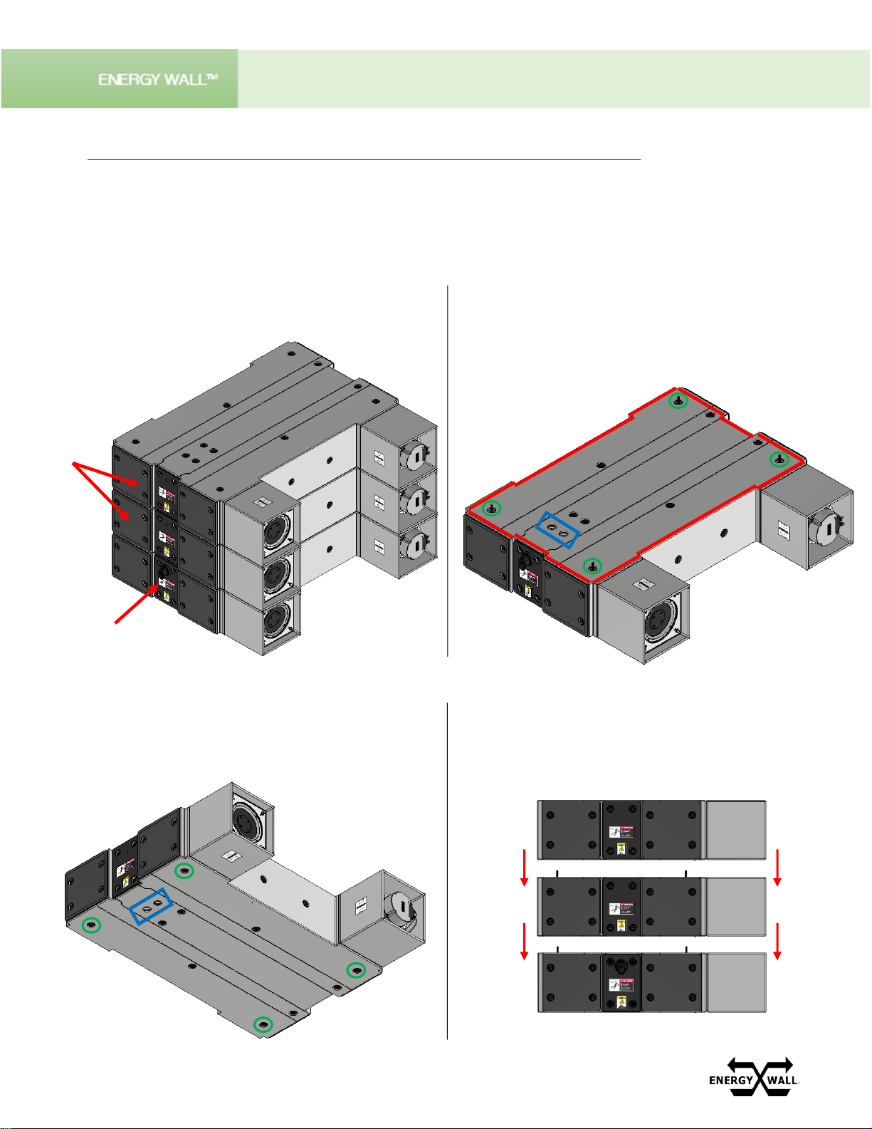
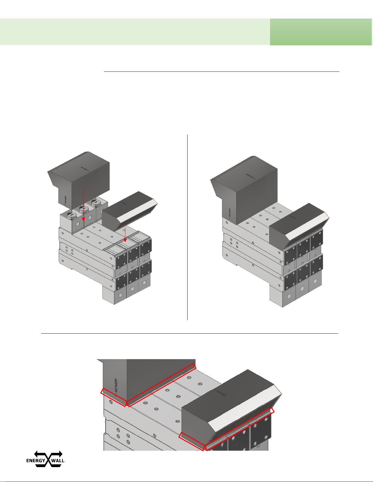
MULTI-UNIT ASSEMBLY
Identify the primary unit with a disconnect handle as
shown below. All secondary units will not have a
disconnect handle.
PRIMARY
UNIT
SECONDARY
UNITS
Once the primary unit is positioned, ensure the
electrical cabinet wire plugs are removed using a
12mm Allen key (blue), perimeter gasketing is
installed at the locations as shown (red), and (4)
connecting bolts are installed in each quadrant (green).
Repeat on all units except the final unit in the system.
Prior to stacking the secondary unit with the primary,
ensure the secondary unit electrical cabinet wire plugs are
removed (blue
) and receiving plugs w/ a 7/16” dia. hole
are installed in each quadrant (green).
Stack the secondary unit to the primary unit as shown.
Tighten the connecting bolts with the hardware
provided and wire each unit per the electrical
schematics. Repeat as necessary to form the desired
system. The final unit will not have connecting bolts.

ENERGYWALL.COM INSTALLATION, OPERATION & MAINTENANCE MANUAL 717.814.5365 5
ENERGY WALLTM
U-ERV/U-HRV
INSTALLATION
GENERAL UNIT SPECIFICATIONS
6ENERGYWALL.COM INSTALLATION, OPERATION & MAINTENANCE MANUAL 717.814.5365
U-ERV/U-HRV
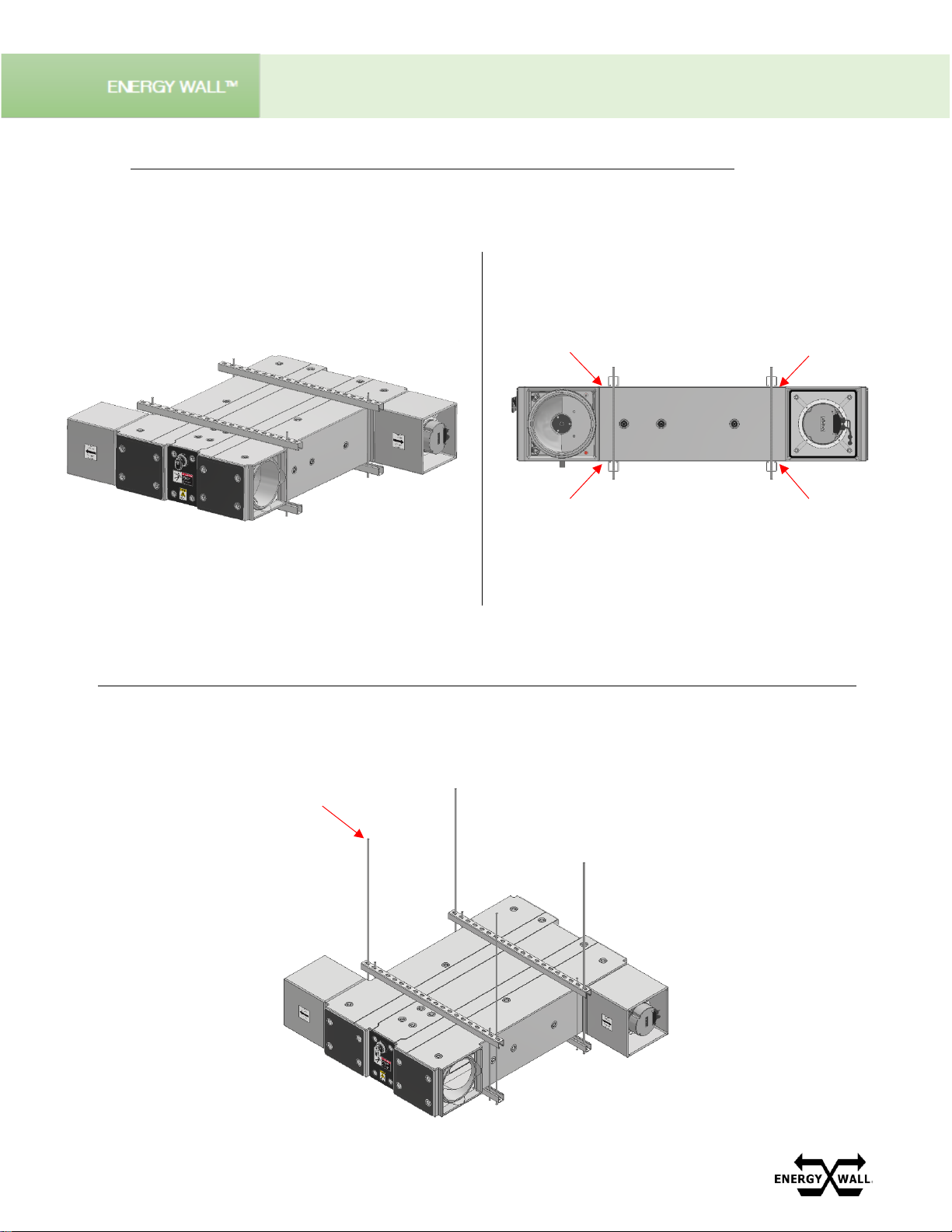
Hang system assembly at desired height using minimum 3/8” dia. all-thread. When mounting the
system on a pad, 3/8” dia. all-thread can be substituted with vertical leg assemblies.
Ensure minimum 1.5” clearance between
Unistrut and system flanges to provide
adequate duct mounting clearance
Side View
INSTALLATION
MECHANICAL –HORIZONTAL RAIL MOUNT
Clamp system between 4 pieces of Unistrut as
shown below with minimum 3/8” dia. all-thread.
Be sure to leave an additional slot on each end to
hang the system.
DO NOT EXCEED 20 IN-LBS OF TORQUE WHEN
CLAMPING THE SYSTEM

ENERGYWALL.COM INSTALLATION, OPERATION & MAINTENANCE MANUAL 717.814.5365 7
ENERGY WALLTM
U-ERV/U-HRV
Clamp system between 4 pieces of Unistrut as
shown below with minimum 3/8” dia. all-thread.
Be sure to leave an additional slot on each end to
hang the system.
DO NOT EXCEED 20 IN-LBS OF TORQUE WHEN
CLAMPING THE SYSTEM
Ensure minimum 1.5” clearance between
Unistrut and system flanges to provide
adequate duct mounting clearance
Side View
Hang system assembly at desired height using minimum 3/8” dia. all-thread. When mounting the
system on a pad, 3/8” dia. all-thread can be substituted with vertical leg assemblies.
INSTALLATION
MECHANICAL –VERTICAL RAIL MOUNT

8ENERGYWALL.COM INSTALLATION, OPERATION & MAINTENANCE MANUAL 717.814.5365
U-ERV/U-HRV
Once the curb is positioned and fastened in
place, apply the supplied gasket around each
flange as shown*
*1800 system shown for reference
Place the first unit on the curb, over the duct
flanges, as shown. In some instances, the fan
cubes will be mounted underneath the unit
as opposed to on top. This is acceptable.
Place the remaining units (if applicable). Fasten
the 4 connecting bolts inside each access panel
with the hardware provided as shown
Once the system is in place, secure it to the curb duct
flanges using #14 x 1.5” long self-drilling screws. A
minimum of 4 screws must be used per unit (i.e. an
1800 system requires at least 12 screws)
INSTALLATION
MECHANICAL –CURB MOUNT
ENERGYWALL.COM INSTALLATION, OPERATION & MAINTENANCE MANUAL 717.814.5365 9
ENERGY WALLTM
U-ERV/U-HRV
When mounted outdoors, an intake is required to eliminate water infiltration into the intake and exhaust ports
of the system. When an intake is required to be installed over a fan cube, it will have an acoustic liner. All
other intakes are unlined. Additional intake options with motorized dampers are available upon request.
Slide the intake hood over the fan cube (left) or
system flange (right) as shown below*
*1800 system shown for reference
Ensure the intake hood’s opening is flush with
the horizontal surface of the system as shown
Once the intake is in place, secure it to the system flanges using #14 x 1.25” long self-drilling screws on all 4
sides. A minimum of 2 screws must be used per unit (i.e. an 1800 system requires at least 6 screws per intake)
INSTALLATION
MECHANICAL –INTAKES, VERTICAL MOUNT
Acoustic
(lined)
Intake
Standard
(unlined)
Intake

10 ENERGYWALL.COM INSTALLATION, OPERATION & MAINTENANCE MANUAL 717.814.5365
U-ERV/U-HRV
Slide the intake hood over the fan cube (right) or
system flange (left) as shown below*
*1800 system shown for reference
Ensure the intake hood’s opening is flush with
the vertical surface of the system as shown
Once the intake is in place, secure it to the
system flanges using #14 x 1.25” long self-
drilling screws on all 4 sides. A minimum of 2
screws must be used per unit (i.e. an 1800
system requires at least 6 screws per intake)
INSTALLATION
MECHANICAL –INTAKE, HORIZONTAL MOUNT
Acoustic
(lined)
Intake
Standard
(unlined)
Intake

ENERGYWALL.COM INSTALLATION, OPERATION & MAINTENANCE MANUAL 717.814.5365 11
ENERGY WALLTM
U-ERV/U-HRV
INSTALLATION
MECHANICAL –DUCTWORK
When designing and installing ductwork to each system, SMACNA guidelines and requirements
must be adhered to. Additionally:
•A single duct run can and should be used for each system.
•It is highly recommended to use insulated duct with a minimum of ¾” thick internal
insulation.
•Flexible duct connections should never be used and avoided at all costs.
•All transitions within the ductwork shall be gradual and all elbowsshall incorporate a radius
on internal and external corners.
•Turning vanes should be utilized whenever possible.
•NEVER USE THE SYSTEM TO SUPPORT DUCTWORK. All ductwork must have
its own support.
•Verify ductwork properly slides over the system flanges (fan cube when applicable). See
next page for recommended duct connection details.
•Minimum straight duct lengths prior to any elbow per the below table must be adhered to.
Additional length is recommended to mitigate sound within the space.
•When installing duct from curb hangers, ensure proper alignment of duct with system
inlet/discharge. Gasket must be used to seal the duct flanges with the underside of the
curb cap. Failure to gasket the ductwork flanges will result in airflow leakage and increases
the potential for condensation formation.
•Secure ductwork to system using #12 or #14 x 1.25” long self-drilling screws. DO NOT
USE LONGER THAN 1.25” SCREWS.
System Size
Recommended
Ductwork Size (IN)
Minimum Straight
Duct Length (IN)
600
12.13 x 12.13
35
1200
12.13 x 24.25
48
1800
12.13 x 36.38
60
2400
12.13 x 48.5
68
3000
12.13 x 60.63
78
3600
12 13 x 72.75
85
4200
12.13 x 84.88
90
4800
12.13 x 97
98
5400
12.13 x 109.13
103
6000
12.13 x 121.25
108

12 ENERGYWALL.COM INSTALLATION, OPERATION & MAINTENANCE MANUAL 717.814.5365
U-ERV/U-HRV
INSTALLATION
MECHANICAL –DUCTWORK
It is highly recommended to A) section the duct that connects to the system with (2) 14” minimum duct
sections, or B) provide access panels within the sides of the duct to allow the system to be easily
serviced. An example of each duct connection recommendation for an 1800 system is shown below.
A*
*TO SERVICE A FAN WITHIN DUCT, REMOVE DUCT “2”, FOLLOWED BY DUCT “1”. ENSURE DUCT “3” IS
INDEPENDENTLY SUPPORTED AND DOES NOT RELY ON THE SYSTEM FOR SUPPORT.
B**
**A WATER-TIGHT ACCESS PANEL CAN BE INSTALLED IN THE LOCATION AND SIZE SPECIFIED WITHIN
THE DUCT TO SERVICE A FAN.
14” MIN
14”
6”
14”
6”
14” MIN
1
2
3
1
2
3
ENERGYWALL.COM INSTALLATION, OPERATION & MAINTENANCE MANUAL 717.814.5365 13
ENERGY WALLTM
U-ERV/U-HRV
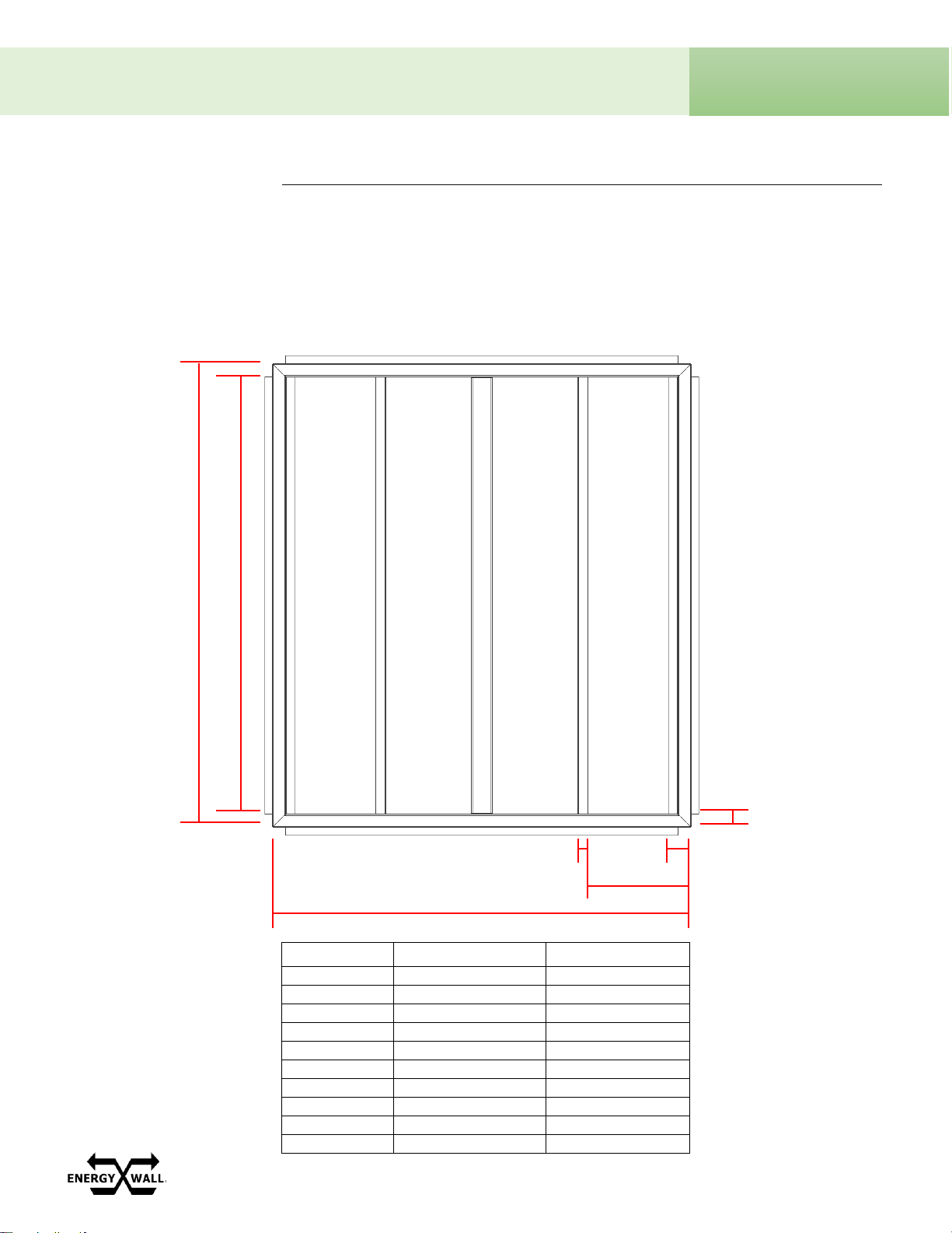
Refer to the table and image below for duct hanger locations within the curb (curb lid not shown).
System Size
A (IN)
B (IN)
600
17.5
13.75
1200
29.75
26
1800
42
38.25
2400
54.25
50.5
3000
66.5
62.75
3600
78.75
75
4200
91
87.25
4800
103.25
99.5
5400
115.5
111.75
6000
127.75
124
INSTALLATION
MECHANICAL –DUCT HANGERS
1.88”
A
B
60.13”
15.5”
3.25”
1.38”

14 ENERGYWALL.COM INSTALLATION, OPERATION & MAINTENANCE MANUAL 717.814.5365
U-ERV/U-HRV
INSTALLATION
ELECTRICAL INFORMATION
The electrical ratings for each system size are listed below. Consult sales for additional voltage and
phase combinations.
SYSTEM ELECTRICAL RATINGS
System
Voltage
Frequency
Phase
FLA
MCA
MOP
600
208-277V
50/60
1
7.4
8.3
15
1200
208-277V
50/60
1
14.3
15.1
20
1800
208-277V
50/60
3
12.2
13.1
15
2400
208-277V
50/60
3
19.3
20.2
25
3000
208-277V
50/60
3
26.2
27
30
3600
208-277V
50/60
3
24.1
25
30
4200
208-277V
50/60
3
31.2
32.1
35
4800
208-277V
50/60
3
38.1
38.9
40
5400
208-277V
50/60
3
36
36.9
40
6000
208-277V
50/60
3
43.1
44
45
As standard, all supply and exhaust fans utilize a state-of-the-art electrically commutated motor
(ECM) to directly drive a mixed flow wheel. Fan specifications are listed below.
FAN DATA
System
Voltage
Frequency
Supply
Fan
Quantity
Exhaust
Fan
Quantity
Max
Supply
HP
Max
Exhaust
HP
Max
Fan
RPM
600
208-277V
50/60
1
1
0.9
0.9
6150
1200
208-277V
50/60
2
2
1.9
1.9
6150
1800
208-277V
50/60
3
3
2.8
2.8
6150
2400
208-277V
50/60
4
4
3.8
3.8
6150
3000
208-277V
50/60
5
5
4.7
4.7
6150
3600
208-277V
50/60
6
6
5.6
5.6
6150
4200
208-277V
50/60
7
7
6.6
6.6
6150
4800
208-277V
50/60
8
8
7.5
7.5
6150
5400
208-277V
50/60
9
9
8.5
8.5
6150
6000
208-277V
50/60
10
10
9.4
9.4
6150

ENERGYWALL.COM INSTALLATION, OPERATION & MAINTENANCE MANUAL 717.814.5365 15
ENERGY WALLTM
U-ERV/U-HRV
The system has (4) ¾” NPT threaded access ports that can be used for power and control wire
connections. (2) on the top and (2) on the bottom. High voltage wires and low voltage wires
should never run in the same conduit as each other, or parallel for long distances.
Top View Bottom View
To remove the threaded plug, a 12mm Allen wrench
is required. Once removed, a ¾” stress relief can be
used to secure the wire run to the system.
Connect power wires to the disconnect and terminal
blocks shown below in red, and control wires (if
applicable) to the terminal blocks and primary controller
shown below in blue. Detailed schematics will be
provided per job.
WARNING: BEFORE PROCEEDING, DISCONNECT POWER TO THE UNIT. WIRING
SHOULD ONLY BE PERFORMED BY AN EXPERIENCED, QUALIFIED ELECTRICIAN
Top View Bottom View
INSTALLATION
ELECTRICAL –SYSTEM WIRING

16 ENERGYWALL.COM INSTALLATION, OPERATION & MAINTENANCE MANUAL 717.814.5365
U-ERV/U-HRV
For applications that require system control and menu navigation from the space, a remote human-machine
interface (HMI) can be used as shown below.
Typical HMI Wiring
The HMI can be mounted in a standard junction box
via the screw holes shown below. All hardware
required to physically mount the HMI is included.
INSTALLATION
ELECTRICAL –REMOTE HMI
UP
DOWN
ENTER
ESC/BACK
PROGRAM
FAULTS
ENERGYWALL.COM INSTALLATION, OPERATION & MAINTENANCE MANUAL 717.814.5365 17
ENERGY WALLTM
U-ERV/U-HRV
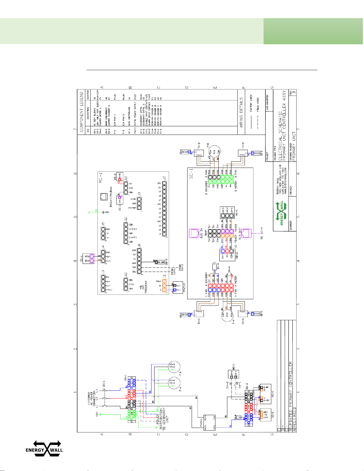
INSTALLATION
ELECTRICAL –GENERAL WIRING SCHEMATIC
18 ENERGYWALL.COM INSTALLATION, OPERATION & MAINTENANCE MANUAL 717.814.5365
U-ERV/U-HRV
Prior to powering the unit, verify there areno loose parts or documentation within the system, or debris
in the airstreams.
1) Inspect all moving parts and verify they are free and clear of any obstructions.
2) Verify all hardware is tight.
3) Verify there are no loose wires.
4) Examine all duct connections and ensure there are no visible gaps that could cause airflow and
water leaks. If any are identified, seal as necessary.
5) Confirm all access panels are secured in place.
6) Once steps 1-5 have been completed, turn the disconnect to the “ON” position.
Most applications will be configured per job from the factory. If new software is required, or the
controller needs to be programmed, follow the “System Commissioning” instructions on page 14 of
this document.
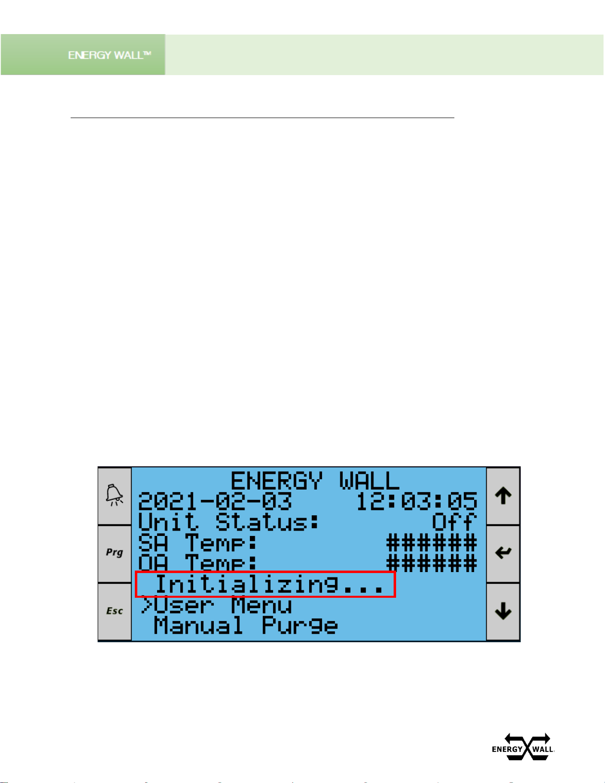
Once the system is powered, it will begin an initialization sequence to identify secondary units. The
initialization sequence can be identified on the remote HMI or main controller home screen as shown
below. This occurs every time the system is power cycled. Once completed, the “Initializing...” term
will no longer be displayed. The system is now ready to operate.
OPERATION
SYSTEM START-UP PROCEDURE
This manual suits for next models
18
Table of contents
Other Energy Wall Fan manuals

Popular Fan manuals by other brands

AccuraSEE
AccuraSEE MINI user manual

Vent-Axia
Vent-Axia Lo-Carbon Silhouette 100HT Installation and wiring instructions

Broan
Broan SKY Series Installation and user guide

Taurus Alpatec
Taurus Alpatec BOREAL 12 ELEGANCE manual

Monte Carlo Fan Company
Monte Carlo Fan Company 3MAVR60RZW Owner's guide and installation manual

Wonderlamp
Wonderlamp W-V000020 manual


Zehnder Rittling
Zehnder Rittling ComfoAir 550 Luxe Installer manual

Fantask
Fantask EP23485WH quick start guide

S&P
S&P HR100V Installation and wiring instructions

twin city
twin city HIB Installation, operation & maintenance manual

Vents
Vents VKMz 100 user manual

Broan
Broan Roomside / Flex Series instructions