ENGELS ENGELCONTROL STBW 225 User manual
Operating Instructions STBW 225
May 2022
Seite 1
ENGELCONTROL
®
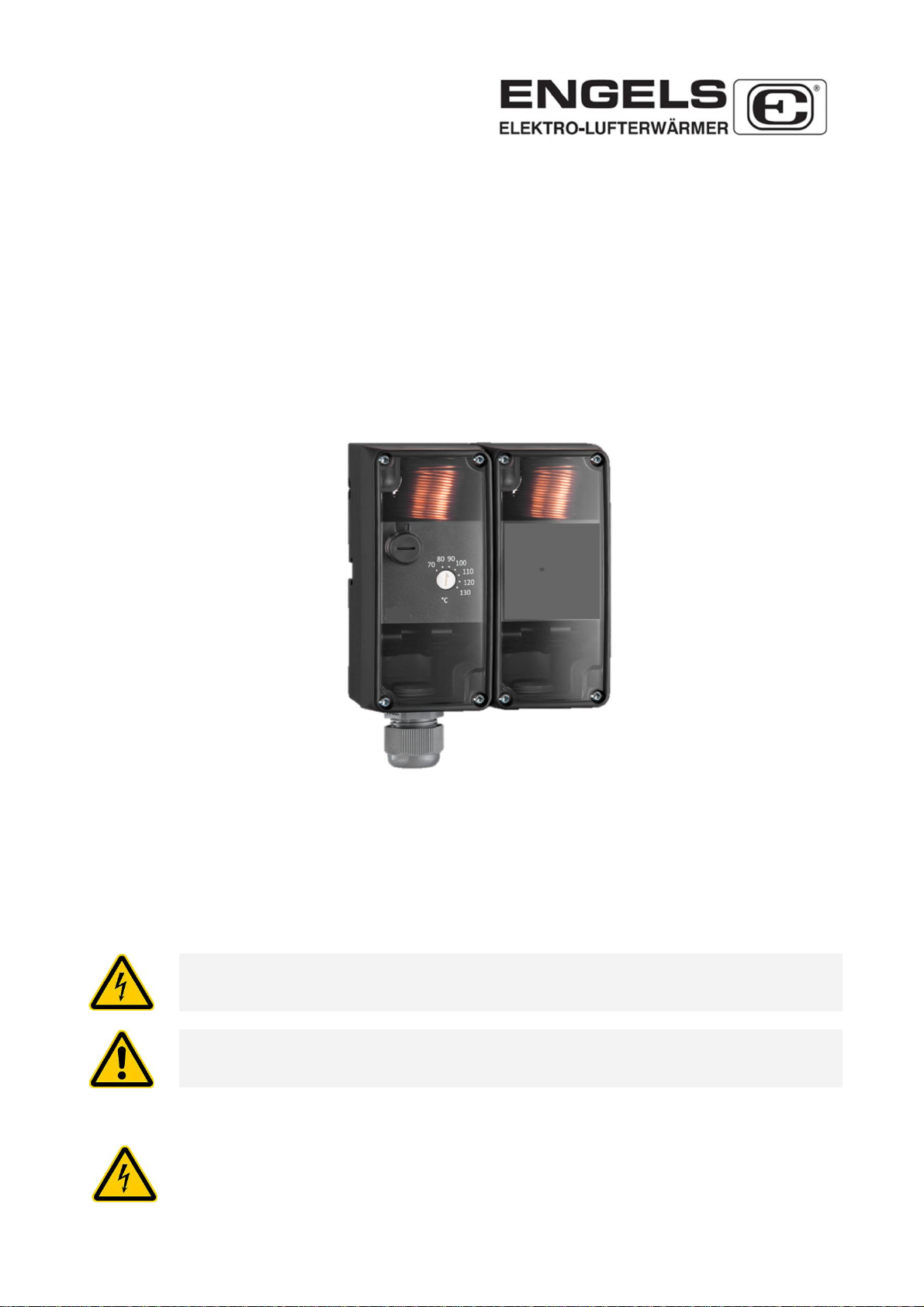
Safety Temperature Limiter
with Temperature Monitor
Type STBW 225 / RTKSA-011.210
for Electric Air Heaters
in Air Conditioning and Ventilation
Notes on Operating Instructions
Please read these operating instructions carefully and observe the relevant country-specific standards, safety
regulations and accident prevention regulations.
The assembly instructions must be kept available during the lifetime of the device.
Passing on and duplicating this document, exploiting and communicating its contents are prohibited, unless
expressly permitted. All rights reserved in the event of patent, utility model or design registration.
The following warnings are used in this manual:
Immediate danger from electrical voltage
Failure to do so can result in serious injury, death, or property damage
have as a consequence.
P
ossible
D
anger
Non-observance can result in serious injuries or damage to property.
1. Safety Instructions
Assembly, electrical installation, commissioning and maintenance of the temperature limiter
may only be carried out by a qualified electrician. The instructions in this manual must be
understood, observed and followed. He is responsible for ensuring that the device is correctly
connected in accordance with the electrical connection diagrams.
The device is maintenance-free.

Operating Instructions STBW 225
May 2022
Seite 2
Kinking and cutting through the sensor lines leads to permanent failure of the device. Filling
liquid can escape if the measuring system breaks. This one isn't dangerous, isn't it irritant, non-
hazardous to health and non-toxic.
The housing may be opened for the electrical connection and parameterization. Inside the
housing there are circuits that are dangerous to touch. The device may only be operated by
personnel who have been authorized and instructed to do so by the system operator. The
applicable standards and guidelines must be observed. The EMC guidelines for the entire
system must be guaranteed.
2. Intended Use
The safety temperature limiters and temperature monitors are only intended for commercial use.
The devices are used for the following purposes:
- For supply air monitoring and as a limiter for electric air heaters and heating registers
- Please also note our information S 20 and A 1999.
- When used in air ducts, a protective coil or immersion sleeve must be used.
- The protective coil has a flange for direct attachment in the air duct. The regulator itself can
be installed later. The controller head is fastened with the screws in the fastening set.
screw and plate by clamping them onto the protective coil (see Fig. 1).
Intended use also includes the following points:
- The instructions in this manual must be observed and followed.
- The technical limit values (see chapter 6 "Technical data") must be observed.
- The probe is to be used exclusively for measuring air
- The devices are not suitable and intended for use in explosive or pressurized areas.
The manufacturer accepts no liability for any resulting damage in the event of improper use, unauthorized
modifications, non-compliance with these instructions or the use of unqualified personnel. The manufacturer's
warranty also expires.
3. Standards and Guidelines
The device conforms to the following requirements:
- DIN EN 14597 temperature control devices and temperature limiters
- DIN EN 60730 Automatic electrical regulation and control devices
4. Function
If the set temperature is reached, the capillary sensor switches the microswitch and the heating contact 1 – 2
opens. Contact 1 – 4 closes. The heating circuit is switched off. In the event of a sensor break, contact 1 - 2 is
permanently opened and contact 1 - 4 is permanently closed in the STB / TW application. Unlocking is no
longer possible with the STB (intrinsic safety).
TW (Temperature Monitor) = internal setting
STB (Safety Temperature Limiter) = internal setting, internal reset

Operating Instructions STBW 225
May 2022
Seite 3
5. Assembly and Installation
Before installing the device, make sure that it is not damaged or has moisture damage,
which may be due to improper transport or storage have arisen.
The housing protection class is IP54. It must be ensured that the housing remains free of
deposits and moisture. The clamps and connecting cables are regularly to be checked for
firm seating and must be free from vibrations.
The ambient temperature limits specified in the technical data must be observed.
5.1 Installation
The thermostats can be installed in the installation position according to DIN 16257 NL 0….NL 90.
The capillary tube must not be shortened or kinked.
6. Electrical Connection
The electrical connection may only be made in a voltage-free state.
The electrical conductors are connected in accordance with the circuit
diagram. The stripping length of 11-13 mm must be observed.
Wire end sleeves must be used when using flexible conductors.
7. Cleaning
Cleaning the opened device is prohibited. dust and dirt with a dry,
solvent-free and soft cloth.
8. Dismantling / Disposal
De-energize before dismantling and secure against being
switched on again.
Dismantle the device and dispose of it properly.

Operating Instructions STBW 225
May 2022
Seite 4
9. Technical Specifications
Max. Switching Current:
Break Contact 16 (2.5) A at 230 VAC + 10 %
0.25 A at 230 VDC + 10 %
Make Contact TW: 6.3 (2.5) A at 230 VAC + 10 %
0.25 A at 230 VDC + 10 %
Make Contact STB: 2.0 (0.4) A at 230 VAC + 10 %
0.25 A at 230 VDC + 10 %
Min. Switching Current: at 24 V (AC/DC) min. 100 mA
Switching Voltage: 24 – 230 VAC 50/60 Hz
24 – 230 VDC
Rated Surge Voltage: 2.5 kV
Electrical Contacts: potential-free switch
Electrical Connection 0.75…2.5 mm² (Push In)
cable gland M 20 x 1,5 mm
Protection Class: I
Degree of Protectiont: IP54 housing
Release Temperature STB: 75°C (- 5 K)
Release Temperature TW: 0…120°C (preset on 50°C)
max. Head Temperature: 80°C
max. Sensor Temperature: full scale +15%
Permitted Storage Temperature: -30° to +80°C
Manual Reset after cooling: about 10 – 15 K
Time Constant: ca. 120 sec. in air
Material Sensor and Capillary: Cu
Protective Coil: length 200 mm
Material Protective Coil: steel nickel-plated
complete type designation: STBW 225 / RTKSA-011.210
Switching off can occur at ambient temperatures below 263 K.
10. Maintenance and Repair
Before commissioning and at sufficient intervals, the measuring system must be checked for functionality.
The intended effect must also be checked here. When cleaning the outside, make sure that the cleaning
agent used does not attack the surface of the plastic housing and the copper of the capillary system.
No liquid or powdery substance must get into the housing.
11. Warranty
The specified technical data was determined in a suitable testing environment and only represents the agreed
quality on this basis. The customer is responsible for checking the suitability for the intended use intended by
the customer or use under the specific conditions of use; we assume no liability for this. Subject to change.
KUNO ENGELS GmbH + Co. • Hauptstrasse 42 • D-42799 Leichlingen
Tel.:+49(0)2174/7900-0 • Fax:+49(0)2174/7900-10 • info@kunoengels.de • www.kunoengels.de
This manual suits for next models
1
Table of contents
Popular Measuring Instrument manuals by other brands


Precision Digital Corporation
Precision Digital Corporation PD687 quick start guide

Titan Logix
Titan Logix TD100 installation guide

Test Equipment Depot
Test Equipment Depot 8758 Operation manual

Ridzewski
Ridzewski Zr-Ox MKII operating manual

Apogee Instruments
Apogee Instruments SP-110 owner's manual

Sam
Sam SAM-III Construction manual