Titan Logix TD100 User manual

TD100
Installation Guide
www.titanlogix.com
Page 1
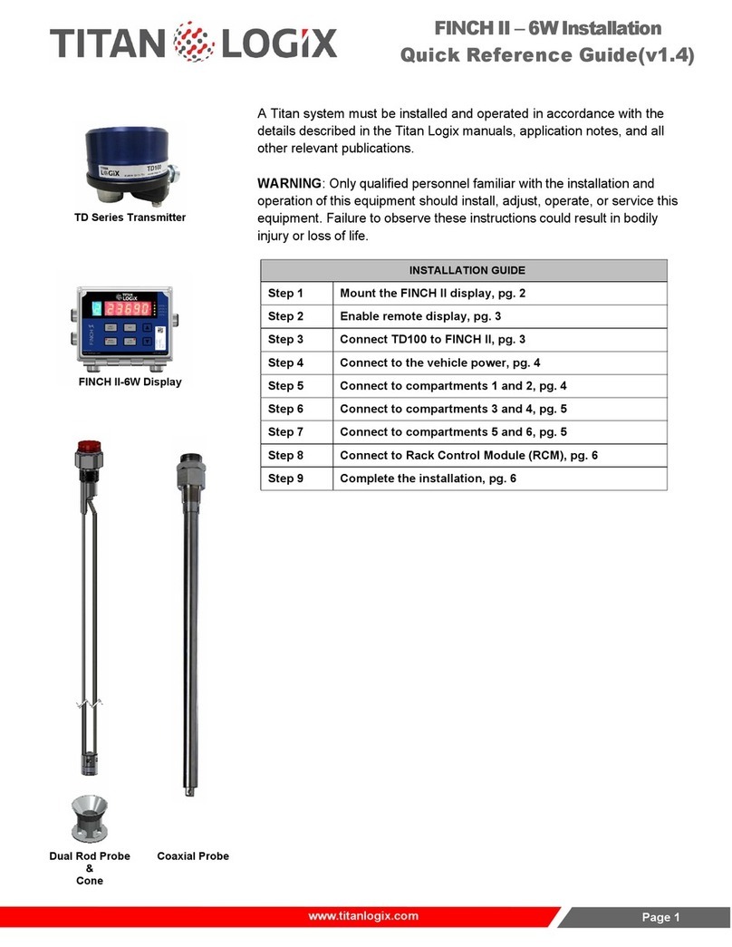
Transmitter
Finch Display
Coaxial Probe
Dual Rod Probe
The TD100 system must be installed and operated in accordance with
the detailsdescribed in the Titan Logix manuals, application notes, and
all other relevant publications.
Only qualified personnel familiar with the installation and operation of this
equipment should install, adjust, operate, or service this equipment.
Failure to observe these instructions could result in bodily injury or loss of
life.
INSTALLATION - MECHANICAL
Step 1
Install Top Fitting (1” NPT Collar), pg. 2
Step 2
Install the Anchor Cone, pg. 2
Step 3
Install the Probe (Coaxial or Dual Rod), pg. 3
Step 4
Offset Measurement, pg. 4
Step 5
Mount the Transmitter, pg. 4
Step 6
Mount the Finch II Display, pg. 5
INSTALLATION - ELECTRICAL
Step 7
Connect Vehicle Power, pg. 7
Step 8
Connect TD100 to Finch II, pg. 7
Step 9
Enable Remote Display, pg. 8
Step 10
Complete the Installation, pg. 8

TD100
Installation Guide
www.titanlogix.com
Page 2
INSTALLATION - MECHANICAL
CHECKLIST
Ensure there are no flammable gases and/or fumes present before installation or repair.
Turn the vehicle power off before any installation activity.
Ensure the tank is drained of liquid and free of vapors.
Observe all federal, state/provincial, and local safety standards and industry best practices.
Ensure all required tools are available for installation.
Refer to the TD100 Installation & Operation Manual (TPM 057), and the Finch II Installation & Operation Manual (TD010)
to view detailed procedures of any steps outlined in this Quick Reference Guide.
Install Top Fitting (1” NPT Collar)
a. Ensure that the top fitting position allows the probe to fit vertically into
the tank.
b. Weld the top fitting to the tank top.
Install the Anchor Cone
a. Ensure that the anchor cone is directly under the collar, within 3
degrees from vertical.
b. Weld the anchor cone to the tank bottom.
1
2
IF THE TOP FITTING AND ANCHOR CONE HAVE ALREADY BEEN INSTALLED BY THE TANK MANUFACTURER,
SKIP STEPS 1 & 2 AND START AT STEP 3.

TD100
Installation Guide
www.titanlogix.com
Page 3
Install the Probe (Coaxial or Dual Rod)
a. Cut the probe to length.
i Dual rod probes are measured from the top of the collar to the
bottom of the cone/bracket. Add 1.5” to calculate the accurate cut
length of the probe (Cut Length = Tank Height + 1.5”).
ii Coaxial probes are measured from the top of the collar to the
bottom of the cone/bracket. Add 1” to calculate the accurate cut
length of the probe (Cut Length = Tank Height + 1”).
3
Tip: The probe has been cut to the proper length when it is fully threaded
into the top fitting with a ½” gap between the bottom of the tank and end
of the probe at the shorting block, inside the anchor cone.
Note: The probe must fit into the anchor cone without bending, twisting, or binding.
This instruction applies to both coaxial and dual rod probes.

TD100
Installation Guide
www.titanlogix.com
Page 4
Offset Measurement
Offset Distance - Without Riser
Offset Distance - With Riser
Mount the Transmitter
a. Inspect the threads for any damage before mounting the transmitter on the
probe. Do not use Teflon tape or anti-seize compound.
b. Hand-tightenthetransmitter nut totheO-ring,thenuse a wrench tosecurethe
connection.
4
5
a. Before installing the probe, measure the Tank Thickness using a
suitable device with 1mm accuracy. Save this measurement for
further calculation.
b. After installing the probe, measure the Probe Offset distance
between the bottom of the probe nut and the outer tank surface
using a suitable device with 1mm accuracy, see Offset Distance -
Without Riser. Save thismeasurement for further calculation.
If the probe is installed on top of the riser, the riser height must be
included in the Probe Offset measure (measuredfrom the bottom
edge of the probe nut to the outer tank surface, see Offset
Distance - With Riser).
c. Calculate the Total Offset by adding the tank thickness value from
step 1a. to the probe offset value from step 1b. Save this offset
measurement value for later use when configuring the system with
the SensorLink software (see Enter Offset Measurement Value,
Step 14).
TOTAL OFFSET = TANK THICKNESS + PROBE OFFSET
Note: In the event it is not possible to measure the tank thickness, use the
recommended tank thickness as provided by the tank manufacturer.

TD100
Installation Guide
www.titanlogix.com
Page 5
Mount the Finch II Display
a. Attach themounting tabs tothe back of the Finch display as shown in
the figure “Finch II Mounting Tabs”.
b. Mount the Finch II, ensuring that the unit is:
i. Installed in a location that does not exceed Class 1, Div. 2
area classification.
ii. Mounted in a protected area, shielded from wheel spray and stones.
iii. Not operated in temperatures less than -40C and greater than +65.
Finch II Mounting Tabs
6

TD100
Installation Guide
www.titanlogix.com
Page 6
INSTALLATION - ELECTRICAL
CHECKLIST
Ensure there are no flammable gases and/or fumes present before installation or repair.
Turn the vehicle power off before any installation activity.
Ensure the tank is drained of liquid and free of vapors.
Ensure all required tools are available for installation.
Secure all wires and cables with clips or cable ties and tighten all compression fittings.
Observe thefollowing instructions during installation:
i. Wire splices should be made inside a weatherproof enclosure or junction box to prevent premature failure due to corrosion.
ii. The TD100 transmitter terminal wiring area forms an explosion-proof enclosure. Care must be taken when opening or
closing the enclosure.
Finch II Display
Finch II Terminals
TD100 Transmitter #1
TD100 Transmitter #2
Remote Acknowledge
Pushbutton (optional)
Finch II Terminals
Electrical Ground
Switched Battery or Acc.
Power
Horn (optional)

TD100
Installation Guide
www.titanlogix.com
Page 7
Connect Vehicle Power
a. TRAILERS - connect the TD100 system power and ground to the
nose box or junction box electrical connector. TRUCKS - connect
TD100 system power to a switched accessory power connection
from the battery.
b. Pass the cable through the strain relief and tighten the strain relief
until the cable cannot be pulled, leaving enough cable inside so the
door can be opened.
Connect TD100 to Finch II
a. Use the Titan supplied explosion-proof harness (wire kit) to
connect the TD100 cable to the Finch II.
b. Insert wires from the explosion-proof elbow into the 1/2” thread for
the connector and tighten the union nut on the TD100 (see top
view).
c. Pull the cable through strain relief on the Finch II and tighten the
strain relief until the cable is secure.
d. Make the following connections:
i. TD 100 Power (PWR) to Finch II Power (PWR) - Black Wire
ii. TD 100 Ground (GND) to Finch II Ground (GND) - White Wire
iii. TD 100 SV (SV Bus) to Finch II SV (SV) - Red or Green Wire
8
Note: Use the appropriate size cable and only one cable per strain relief for
optimized performance and to prevent water ingress.
7

TD100
Installation Guide
www.titanlogix.com
Page 8
Enable Remote Display
a. To enable the display to stay ON while in use, access the Finch II
circuit board, and make a connection between DISPLAY EN and GND
using a jumper wire as shown.
Complete the Installation
a. Replace the Finch II circuit board cover and any other system cover/
enclosure, ensuring all connections are secure before applying
power to the TD100 system.
b. In the event error messages are observed when applying power to the
system, refer to the Troubleshooting section of the TD100 Installation
& Operation Manual (TPM 057).
9
10
Other manuals for TD100
2
Table of contents
Other Titan Logix Measuring Instrument manuals
