Choice Select CHO4020 User manual

Page 1
STEREO POWER AMPLIFIER
CHO4020 100 watt
CHO4021 200 watt
CHO4022 400 watt

Page 2
WARNING: When using electrical products, basic precautions should
always be observed, including the following:
1. Read these instructions thoroughly and retain for future reference.
2. Head all warnings, and follow all instructions.
3. Do not use this apparatus near water.
4. Clean only with a dry cloth.
5. Do not block any of the ventilation openings. Install in
accordance with manufacturer’s instructions.
6. Do not install near any heat sources such as radiators, heat
registers, stoves or other apparatus (including amplifiers) that
produce heat.
7. Do not disable the safety purpose of the polarized plug, or
grounding-type plug. A polarized plug has two blades with one
prong wider than the other. A grounding plug has two blades and
a third grounding prong. The wide blade or third prong is
provided for your safety. Never break off the ground pin. Connect
only to a power supply of the type marked on the unit adjacent to
the power supply cord. If the provided plug does not fit into your
outlet, consult an electrician for replacement of the obsolete
outlet.
8. Protect the power cord from being pinched or stepped on,
particularly at plugs, convenience receptacles, and the point at
which they exit from the apparatus.
9. Use only those attachments/accessories provided by the
manufacturer.
10. Unplug this apparatus during lightning storms, or when unused for
long periods of time.
11. Refer all servicing to qualified service personnel. Servicing is
required when the apparatus has been damaged in any way, such
as: power cord or plug is damaged, liquid has been spilled or
objects have fallen into the apparatus, the apparatus has been
exposed to rain or moisture, the apparatus does not operate
normally or the apparatus has been dropped.
12. If this apparatus is to be mounted in an equipment rack, rear
support should be provided.
13. Exposure to extremely high noise levels may cause permanent
hearing loss. Individuals vary considerably in susceptibility to
noise-induced hearing loss, but nearly everyone will lose some
hearing if exposed to sufficiently intense noise for a sufficient
time. The U.S. Government’s Occupational and Health
Administration (OSHA) has specified the following permissible
noise level exposures:
Duration per Day in Hours Sound Level dBA, Slow Response
8 90
6 92
4 95
3 97
2 100
1-1/2 102
1 105
1/2 110
1/4 or less 115
According to OSHA, any exposure in excess of the above permissible
limits could result in some hearing loss. Ear plugs or protectors to the
ear canals or over the ears must be worn when operating this
amplification system in order to prevent a permanent hearing loss, if
exposure is in excess of the limits as set forth above. To ensure
against potentially dangerous exposure to high sound pressure levels,
it is recommended that all persons exposed to equipment capable of
producing high sound pressure levels such as this amplification system
be protected by hearing protectors while the unit is in operation.

Page 3
CAUTION: Risk of electrical shock
DO NOT OPEN!
CAUTION: To reduce the risk of electric
shock, do not remove cover. No user serviceable parts
inside. Refer servicing to qualified service personnel.
WARNING: To prevent electrical shock or fire hazard,
this apparatus should not be exposed to rain or
moisture, and objects filled with liquids, such as vases,
should not be placed on this apparatus, Before using
this apparatus, read this operating guide for further
warnings.
Congratulations!
You have just purchased a highly reliable, professional Choice
Select Power Amplifier. These amplifiers are ruggedly
constructed rack mount units with numerous input/output
connections for installation flexibility and convenience. Front
panel features include calibrated gain (dB) controls with LED
power level indicators.
Modern power amplifiers are sophisticated pieces of engineering
capable of producing extremely high power levels. They will
provide many years of reliable service.
Correctly installing and connecting the amplifier is very
important. Please take the time to study this manual so that you
can obtain the best
p
ossible service
f
or
y
our am
p
lifier.
Page 4
2. SETUP
2.1 Unpack Your Amplifier
Please unpack and inspect your amplifier
for any damage that may have occurred
during transit. If damage is found, notify the
transportation company immediately. Save
the shipping carton as evidence of damage
for the shipper’s inspection.
It is also recommended that you save all
packing materials so you will have them if
you ever need to transport the unit. Never
ship the unit without adequate packing.
YOU WILL NEED (not supplied):
• Input wiring cables
• Output wiring cables
WARNING: Before you start to
set up your amplifier, make sure you
read and observe the Important Safety
Instructions found at the beginning of
this manual.
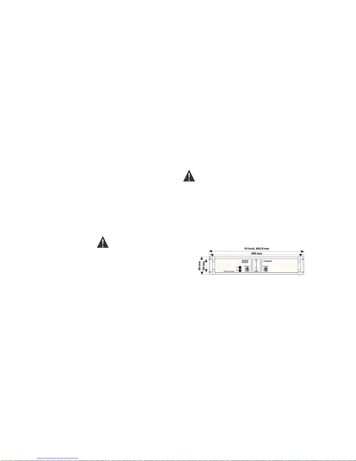
2.2 Install Your Amplifier
CAUTION Before you begin, make
sure your amplifier is disconnected from
the power source, with power switch in
the “OFF” position and all level controls
turned completely down (counter-
clockwise).
This amplifier may be rack-mounted using a
standard 19-inch equipment rack. See
Figure 2.2 for amplifier dimensions. You
may also stack amps without using a
cabinet.
NOTE: When transporting, amplifiers
should be supported at both front and back.
2.3 Ensure Proper Cooling
When using an equipment rack, mount
units directly on top of each other. Close
any open spaces in rack with blank panels.
DO NOT block front or rear air vents. The
side walls of the rack should be a minimum
of 2 inches away from the amplifier sides,
and the back of the rack should be a
minimum of 4 inches from the amplifier
back panel.
Figure 2.2 Amplifier Dimensions

Page 5
2.4 Choose Input Wire and Connectors
You have 3 choices of input connectors:
1/4-inch phone, 3-pin XLR, or RCA inputs.
You can also use either balanced or
unbalanced wiring.
Figure 2.4.1 shows balance connector pin
assignments for XLR and phone. Figure
2.4.2 shows unbalanced connector pin
assignments for XLR and phone. RCA
connectors are unbalanced.
Both channels should be wired using a
common center terminal for ground
connection.
NOTE: Custom wiring should
only be performed by qualified
personnel.
Figure 2.4.1 Balanced Input
Connector wiring Figure 2.4.2 Unbalanced Input
Connector wiring

Page 6
2.5 Choose Output Wire and Connectors
Choice Select recommends using pre-built or professionally wired,
high-quality, two-or four-conductor, heavy gauge speaker wires. They
should be terminated with Neutrik Speakon™ NL4FC connectors
(Figure 2.5.1) at one end and appropriate connectors to fit your
speakers at the other end.
Using the guidelines below, select the appropriate size of wire based
on the distance from amplifier to speaker.
Distance Wire Size
Up to 25 ft. 16 gauge
26-40 ft. 14 gauge
41-60 ft. 12 gauge
61-100 ft. 10 gauge
101-150 ft. 8 gauge
151-250 ft. 6 gauge
CAUTION: never use shielded cable for output wiring.
Figure 2.5.1 Neutrik Speakon™ Connector
Figure 2.5.2 The Binding Post Output Connectors can be
direct-wired oor will accept banana plugs.

Page 7
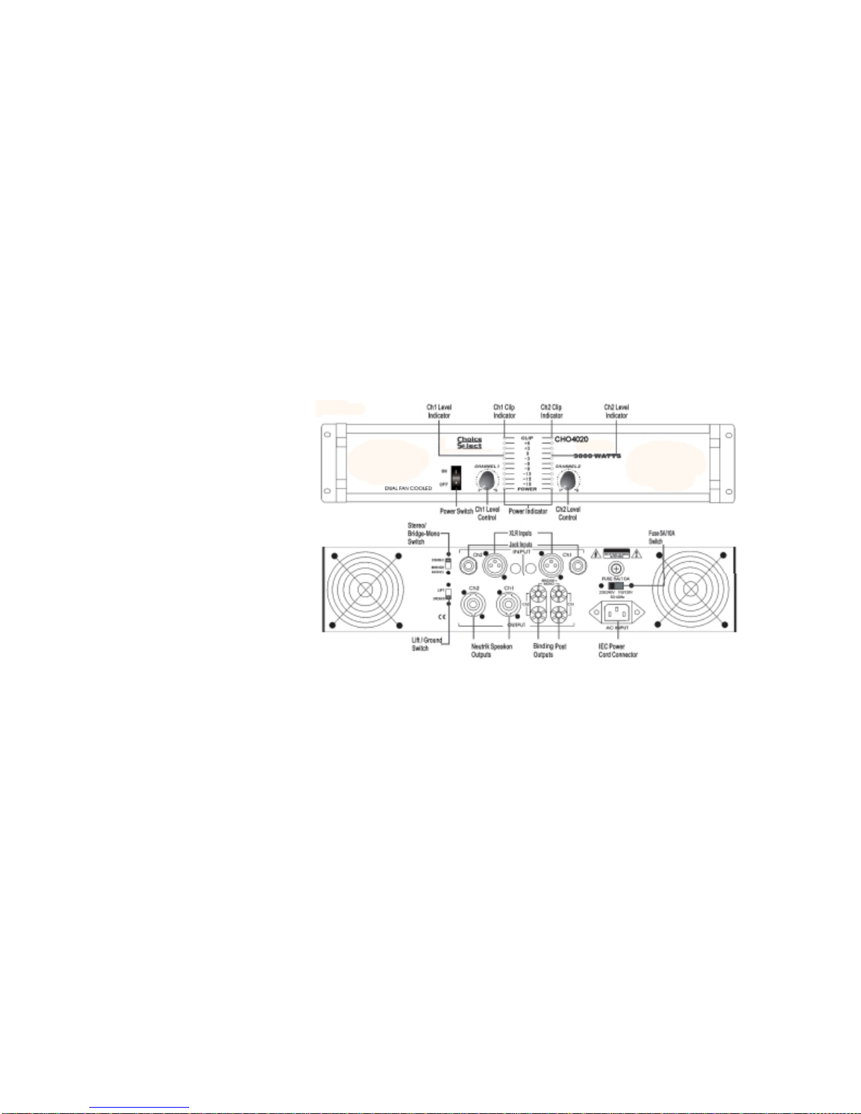
2.6 Wire Your System
2.6.1 Stereo Mode
Make sure the amplifier is turned off and
the level controls are turned down before
you wire the system.
Typical input and output wiring is shown in
Figure 2.6.1.
INPUTS: Connect input wiring for each
channel.
OUTPUTS: Maintain proper polarity (+/-)
on output connectors.
Connect Channel-1 positive (+) speaker
load to Channel-1 positive terminal of amp;
repeat for negative (-). Repeat each
channel wiring as for Channel-1. Make sure
the Mode switch is set to the “Stereo”
position when operating in Stereo mode.
(See the next page for Bridge-Mono wiring.)
Figure 2.6.1 Typical System Wiring, Stereo Mode

Page 8
2.6.2 Bridge-Mono Mode
Make sure the amplifier is turned off and
the level controls are turned down before
you wire the system.
Typical input and output wiring is shown in
Figure 2.6.2.
INPUTS: Connect input wiring to CH 1.
OUTPUTS: We recommend direct wiring to
the binding posts for bridged mono
operation. Connect the speaker (load) using
both of the red binding posts. Do not use
the black posts in the Bridged mode.
Make sure the Mode switch is set to the
“Bridge Mono” position when operating in
Bridge-Mono mode.
NOTE: Turn down the Channel 2 level
control when operating the channel pair
in Bridge-Mono mode, as the Channel 1
level control works both channels.
Figure 2.6.2 Typical System Wiring, Bridge-Mono Mode
Page 9
3. Operation
NOTE: For use in the USA, power switch (located above “AC INPUT” on back panel) should be set to “110/120V 50-60Hz” position.
NOTE: In rare situations a ground loop may produce an AC hum. “Lifting” the ground may eliminate the hum. However, to be properly grounded the
“Lift/Ground” switch should be set to “Ground”. The amplifier will not be grounded if the switch is set to “Lift”.

Page 10
SPECIFICATIONS
CHO4020 CHO4021 CHO4022
2-channel
Stereo Output
(8 ohm load) 100 watts RMS 200 watts RMS 400 watts RMS
Bridge-Mono
Output
(4 ohm load) 200 watts 400 watts 800 watts
Power
Consumption <=250w <=400w <=800w
Protection Fuse and Thermal Breaker
Distortion 20Hz~20KHz <= 0.1%
Weight 14.33 lbs 16.53 lbs 19.84 lbs
Dimensions 21.26” x 14.37”
x 6.69” 21.26” x 19.09”
x 6.69” 21.26” x 20.08”
x 6.69”
This manual suits for next models
2
Table of contents
Other Choice Select Amplifier manuals


Popular Amplifier manuals by other brands


PDA Range
PDA Range 103 installation instructions

Optimus
Optimus A-5120M2 Installation and operating instructions

Aunex
Aunex AC 5 Series Installation and operation manual

Phasemation
Phasemation EA-500 owner's manual

PS Engineering
PS Engineering PRD60 Installation and operation manual

Q4 audio
Q4 audio PTH 9 user manual


