ennoLogic eM860T True RMS User manual

eM860T True RMS Multimeter
User Manual

Version 1.4. Revised 3/19/2015.
© 2015 ennoLogic™. All rights reserved.
http://ennologic.co

TABLE OF CONTENTS
1. GENERAL INSTRUCTIONS ................................................. 1
1.1 Precautionary Safety Measures .......................................... 1
1.1.1 Preli inary ............................................................... 2
1.1.2 During Use ............................................................... 4
1.2 Battery Installation or Replacement ................................... 7
1.3 Symbols ............................................................................... 9
1.4 Instructions ......................................................................... 9
2. INSTRUMENT DESCRIPTION ........................................... 11
2.1 Main User lements .......................................................... 11
2.2 LCD Display ....................................................................... 13
2.3 Keypad .............................................................................. 15
2.3.1 SELECT ................................................................... 15
2.3.2 HOLD/BACKLIGHT ............................................. 15
2.3.3 RANGE ................................................................... 15
2.3.4 REL△ ....................................................................... 16
2.3.5 Hz % ........................................................................ 16
2.3.6 MAX/MIN .............................................................. 16

3. FUNCTION DESCRIPTION ................................................ 17
3.1 General Functions ............................................................. 17
3.1.1 DATA HOLD ode .............................................. 17
3.1.2 Manual ranging and Autorange ode ............... 17
3.1.3 Battery Saver .......................................................... 18
3.1.4 Relative Measure ent Mode ............................... 19
3.1.5 TRUE RMS Measure ent .................................... 19
3.2 Measurement Functions ................................................... 20
3.2.1 AC and DC Voltage easure ent ..................... 20
3.2.2 Resistance Measure ent ...................................... 23
3.2.3 Capacitance Measure ent ................................... 26
3.2.4 Continuity Check .................................................. 28
3.2.5 Diode Test .............................................................. 31
3.2.6 Frequency and Duty Cycle Measure ent ......... 34
3.2.7 Te perature Measure ent ................................. 35
3.2.8 Current Measure ent .......................................... 36
3.2.9 NCV (Non-Contact Voltage Detect) ................... 38
4. TECHNICAL SPECIFICATIONS ........................................ 39

4.1 General specifications ....................................................... 39
4.2 Measurement Specifications ............................................ 40
4.2.1 Voltage .................................................................... 40
4.2.2 Frequency ............................................................... 42
4.2.3 Resistance ............................................................... 42
4.2.4 Diode Test .............................................................. 43
4.2.5 Continuity Check .................................................. 43
4.2.6 Capacitance ............................................................ 43
4.2.7 Te perature ........................................................... 44
4.2.8 Current .................................................................... 44
5. MAINTENANCE .................................................................. 45
5.1 General Maintenance ....................................................... 46
5.2 Fuse replacement ............................................................. 46
6. ACCESSORIES ....................................................................... 47


1
1. GENERAL INSTRUCTIONS
This instru ent co plies with IEC 61010-1: 2001, CAT Ⅲ
1000V and CAT Ⅵ 600V overvoltage standards. See
Specifications.
To get the best service fro this instru ent, read this user's
anual carefully and respect the detailed safety
precautions.
International sy bols used on the Meter and in this anual
are explained in chapter 1.2.
1.1 Precautionary Safety Measures
I portant Note: Li ited Liability
Cascadia Innovations is the exclusive distributor of all
ennoLogic™ products. Except as explicitly stated,
Cascadia Innovations is not liable for direct, indirect,
incidental, or other types of da ages arising out of, or
resulting fro the use of this product. By using the
eM860T you agree to hold ennoLogic™ and Cascadia
Innovations har less for any and all consequences of the
use of this product or application of data fro the use of
this instru ent.

2
1.1.1 Preli inary
As the possibilities of high transient over-voltages occurring
in today’s power syste s increase, ore stringent safety
standards are set for electrical test equip ent. Transients on
electrical syste s (power grid, feeder or branch circuits) will
trigger a series of incidents that ay result in serious
personal injury. To protect you against transients, safety
ust be built into the test equip ent.
Overvoltage
category In brief Exa ples
CAT I Electronic
• Protected electronic
equip ent.
• Equip ent connected to
(source) circuits in
which easures are
taken to li it transient
over-voltages to an
appropriately low level.
• Any high-voltage, low-
energy source derived
fro a high winding
resistance transfor er,
such as the high-voltage
section of a copier.

3
CAT II
Single-phase
receptacle
connected
loads
• Appliance, portable
tools, and other household
and si ilar loads.
• Outlet and long branch
circuits.
• Outlets at ore than 10
eters (30 feet) fro CAT
III source.
• Outlets at ore that 20
eters (60 feet) fro CAT
IV source.
CAT III
Three-phase
distribution,
including
single-phase
co ercial
lighting
• Equip ent in fixed
installations, such as
switchgear and polyphase
otors.
• Bus and feeder in
industrial plants.
• Feeders and short
branch circuits,
distribution panel devices.
• Lighting syste s in
larger buildings.
• Appliance outlets with
short connections to
service entrance.

4
CAT VI
Three-phase at
utility
connection,
any outdoor
conductors
• Refers to the “origin of
installation”; i.e., where
low-voltage connection
is ade to utility power.
• Electricity eters,
pri ary overcurrent
protection equip ent.
• Outside and service
entrance, service drop
fro pole to building,
run between eter and
panel.
• Overhead line to
detached building,
underground line to well
pu p.
When using this Multi eter, the user ust observe all
nor al safety rules concerning:
•protection against the dangers of electric current.
•protection of the Multi eter against isuse.
For your own safety, only use the test probes supplied with
the instru ent. Before use, check that they are in good
condition.
1.1.2 During Use

5
•If the eter is used near noise generating equip ent, be
aware that display ay beco e unstable or indicate large
errors.
•Do not use the eter or test leads if they look da aged.
•Use the eter only as specified in this anual; otherwise,
the protection provided by the eter ay be i paired.
•Use extre e caution when working around bare
conductors or bus bars.
•Do not operate the eter around explosive gas, vapor, or
dust.
•Verify a Meter's operation by easuring a known
voltage. Do not use the Meter if it operates abnor ally.
Protection ay be i paired. When in doubt, have the
Meter serviced.
•Use the proper ter inals, function, and range for your
easure ents.
•When the range of the value to be easured is unknown,
check that the range initially set on the ulti eter is the
highest possible or, wherever possible, choose the
autoranging ode.
•To avoid da age to the instru ent, do not exceed the
axi u li its of the input values shown in the
technical specification tables.
•When the ulti eter is linked to easure ent circuits,
do not touch unused ter inals.
•Caution when working with voltages above 60Vdc or 30V
AC r s. Such voltages pose a shock hazard.

6
•When using the probes, keep your fingers behind the
finger guards.
•When aking connections, connect the co on test lead
before connecting the live test lead; when disconnecting,
disconnect the live test lead before disconnecting the
co on test lead.
•Before changing functions, disconnect the test leads fro
the circuit under test.
•For all DC functions, including anual or auto-ranging,
to avoid the risk of shock due to possible i proper
reading, verify the presence of any AC voltages by first
using the AC function. Then select a DC voltage range
equal to or greater than the AC range.
•Disconnect circuit power and discharge all high-voltage
capacitors before testing resistance, continuity, diodes, or
capacitance.
•Never perfor resistance or continuity easure ents on
live circuits.
•Before easuring current, check the eter's fuse and turn
off power to the circuit before connecting the eter to
•the circuit.
•In TV repair work, or when carrying out easure ents
on power switching circuits, re e ber that high
a plitude voltage pulses at the test points can da age
the ulti eter. Use of a TV filter will attenuate any such
pulses.

7
•Use just one 6F22 battery, properly installed in the
Meter's battery case, to power the Meter.
•Replace the battery as soon as the battery indicator
() appears. A low battery ight produce false
readings that can lead to electric shock and personal
injury.
•Do not easure voltages above 1000V in Category III, or
600V in Category Ⅳ installations.
•When in REL ode, the “REL” sy bol is displayed.
Caution ust be used because hazardous voltage ay be
present.
•Do not operate the Meter with the case (or part of the
case) re oved.
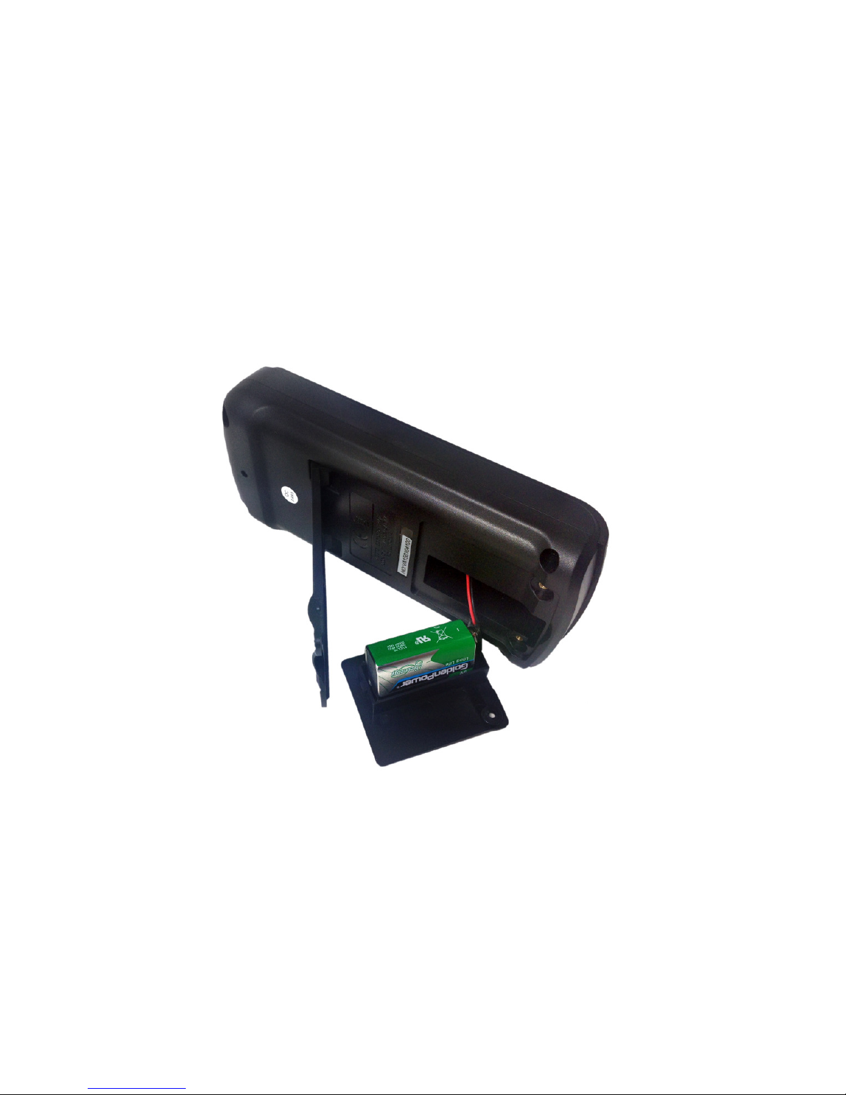
1.2 Battery Installation or Replace ent
To avoid false readings, which could lead to
possible electric shock or personal injury, replace
the battery as soon as the battery indicator
() appears.
Before installing or replacing the battery,
disconnect test leads and/or any connectors from
any circuit under test, turn the meter off and remove
test leads from the input terminals.
8
1. Set rotary switch to the OFF position.
2. Disconnect test leads and/or any connectors fro the
ter inals.
3. Re ove the red protective rubber casing by carefully
peeling it away fro the black plastic enclosure.
4. Use a screwdriver to unscrew the two screws on the
battery cover, on the back of the unit near the botto .
5. Re ove the battery cover fro the eter.
6. If you are replacing the battery: re ove the used battery
7. Install a new 9V battery (6F22).
8. Replace the battery cover and tighten the screws.
9. Attach protective rubber casing.

9
1.3 Sy bols
Sy bols used in this anual and on the instru ent:
aution: refer to the instruction anual.
Incorrect use ay result in da age to the device
or its co ponents.
~ AC (Alternating Current)
DC (Direct Current)
AC or DC
Earth ground
Double insulated
Fuse
Confor s to European Union directives
1.4 Instructions
•Re ove test leads fro the Meter before opening the
Meter case or battery cover.
•When servicing the Meter, use only specified replace ent
parts.
•Before opening up the instru ent, always disconnect
fro all sources of electric current and ake sure you are

10
not charged with static electricity, which ay destroy
internal co ponents.
•Any adjust ent, aintenance or repair work carried out
on the eter while it is live should be carried out only by
appropriately qualified personnel, after having taken into
account the instructions in this anual.
•A "qualified person" is so eone who is fa iliar with the
installation, construction and operation of the equip ent
and the hazards involved. He is trained and authorized to
energize and de-energize circuits and equip ent in
accordance with established practices.
•When the instru ent is opened up, re e ber that so e
internal capacitors can retain a dangerous potential even
after the instru ent is switched off.
•If any faults or abnor alities are observed, take the
instru ent out of service and ensure that it cannot be
used until it has been checked out.
•If the eter is not going to be used for a long ti e, take
out the battery and do not store the eter in high
te perature or high hu idity environ ents.

11
2. INSTRUMENT DESCRIPTION
2.1 Main User Ele ents
The front panel is shown in Figure 2-1, and its user
ele ents are described below:
① LCD display: Used for displaying easure ent results
and various sy bols.
② Keypad: Measure ent function keys.
③ Rotary switch: Used for selecting easure ent
functions.
④
V
Hz
:
Connection ter inal for the red test lead during
voltage, resistance, capacitance, frequency,
te perature, diode and continuity easure ents.
⑤ uA/ A:
Connection ter inal for the red test lead during µA
and A easure ents.
⑥ A:
Connection ter inal for the red test lead during 6A
and 10A easure ents.
⑦ COM:
Connection ter inal for the black test lead (co on
reference.)

12
Figure 2-1: Meter Front Panel

13
2.2 LCD Display
Figure 2-2: LCD Display
The LCD screen is shown in Figure 2-2 above, and the
eanings of the sy bols are explained in Table 1 below:
No.
Sy bol Meaning
1 Indicates negative readings
2
Indicator for AC voltage or
current

14
3
Indicator for DC voltage or
current
4 AUTO
The eter is in the Autorange
ode in which the eter
auto atically selects the range
with the best resolution.
5 NCV No-contact AC Voltage detect
6 H The eter is in Data Hold
ode.
7 REL The eter is in Relative
Measure ent ode.
8 MAX Display axi u data
9 MIN Display ini u data
10 Low battery indication
11 The eter is in Continuity
Check ode.
12 The eter is in Diode Test
ode.
13 %°C°F KMΩ
ΩΩ
ΩHz
nμ FAV Measure ent units
14
This sy bol eans that the
input is too large for the
selected range.
Table 1: LCD Display Sy bols
Other manuals for eM860T True RMS
1
Table of contents
Other ennoLogic Multimeter manuals


