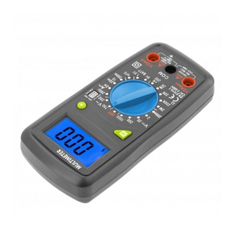
HOGERT HT1E620 User manual

1
Adres producenta/ Adresse des Herstellers/ Manufacturer’s Address/ Адрес производителя
GTV Poland Sp. z o.o. Sp. k., ul. Przejazdowa 21, 05-800 Pruszków
PL
INSTRUKCJA OBSŁUGI
MULTIMETR CYFROWY HT1E620
Dziękujemy za zakup naszego produktu. Wyprodukowany zgodnie z wyso-
kim standardem produkt zapewni lata bezproblemowej pracy pod warun-
kiem stosowania zgodnie z instrukcją i odpowiednio utrzymany.
OCHRONA ŚRODOWISKA
Symbol wskazujący na selektywne zbieranie zużytego sprzętu
elektrycznego i elektronicznego. Zużyte urządzenia elektryczne
są surowcami wtórnymi – nie wolno wyrzucać ich do pojemni-
ków na odpady domowe, ponieważ zawierają substancje nie-
bezpieczne dla zdrowia ludzkiego i środowiska! Prosimy o ak-
tywną pomoc w oszczędnym gospodarowaniu zasobami
naturalnymi i ochronie środowiska naturalnego przez przekazanie zużytego
urządzenia do punktu składowania zużytych urządzeń elektrycznych. Aby
ograniczyć ilość usuwanych odpadów konieczne jest ich ponowne użycie,
recykling lub odzysk w innej formie.
INFORMACJE OGÓLNE
Urządzenie jest przeznaczone do użytku zarówno w prywatnych gospodar-
stwach domowych jak i do użytku komercyjnego.
Multimetr cyfrowy to inteligentny, automatyczny zintegrowany ręczny przy-
rząd (6000 zliczeń) z funkcją TRUE RMS. Został zaprojektowany i wyprodu-
kowany zgodnie z normami bezpieczeństwa EN61010-1, EN61010-2-030 i
EN61010-2-032 dla elektronicznego przyrządu pomiarowego i podręcznego miernika cęgowego. Jest zgodny z CAT III 600 V i normami
bezpieczeństwa poziomu zanieczyszczenia 2. Przed użyciem tego urządzenia należy uważnie przeczytać instrukcję obsługi i zwrócić
uwagę na powiązane standardy bezpieczeństwa pracy.
Wszelkie inne sposoby użytkowania nie są zamierzone i mogą prowadzić do uszkodzenia mienia lub nawet obrażeń ciała. Urządzenie
należy używać wyłącznie zgodnie z niniejszą instrukcją obsługi. Producent nie ponosi żadnej odpowiedzialności za uszkodzenia spo-
wodowane użytkowaniem niezgodnym z przeznaczeniem. Urządzenie nie jest przyrządem pomiarowym w rozumieniu ustawy “Prawo
o pomiarach”.
OGÓLNE WARUNKI BEZPIECZEŃSTWA
W zakresie właściciela i użytkownika jest przeczytanie, zrozumienie i przestrzeganie poniższych zasad:
WAŻNE: Proszę przeczytać tą instrukcję uważnie. proszę zwrócić szczególną uwagę na wymogi bezpiecznego użytkowania,
ostrzeżenia i uwagi. używać produkt prawidłowo i z uwagą do celów, do których został przeznaczony. nieprzestrzeganie tego
może spowodować uszkodzenie i/lub uszczerbek zdrowia i spowoduje utratę gwarancji. proszę przechowywać instrukcję w
bezpiecznym miejscu w celu dalszego używania. przekazując urządzenie innej osobie, oddaj jej także instrukcję obsługi.
• Proszę wykorzystywać urządzenie jedynie dla celu, jaki został przewidziany dla urządzenia.
• Proszę trzymać urządzenie z daleka od ciepła, bezpośredniego promieniowania słonecznego, wilgoci (w żadnym wypadku nie zanurzać
w substancjach płynnych) oraz ostrych krawędzi. Proszę nie obsługiwać urządzenia wilgotnymi dłońmi.
• Pracującego urządzenia nie należy pozostawiać bez nadzoru. Przed opuszczeniem pomieszczenia urządzenie należy zawsze wyłączyć.
• Należy regularnie sprawdzać, czy urządzenie. W razie uszkodzenia należy przestać korzystać z urządzenia.
• Dla bezpieczeństwa dzieci proszę nie zostawiać swobodnie dostępnych części opakowania (torby plastikowe, kartony, styropian, itp.).
OSTRZEŻENIE
Nie pozwalaj dzieciom bawić się folią. Niebezpieczeństwo uduszenia!
To urządzenie nie jest przeznaczone do użytku przez osoby z ograniczonymi zdolnościami fizycznymi, sensorycznymi lub umysłowymi
lub brakiem doświadczenia i / lub umiejętności, chyba że takim osobom towarzyszą i są nadzorowane przez osoby odpowiedzialne
za ich bezpieczeństwo lub otrzymały precyzyjne instrukcje użytkowania tego urządzenia i zrozumiały wynikające z tego ryzyko. Dzieci
mogą korzystać z tego urządzenia tylko w wieku powyżej 8 i pod nadzorem osoby odpowiedzialnej za ich bezpieczeństwo lub jeśli
otrzymały instrukcje użytkowania tego urządzenia i zrozumiały wynikające z tego ryzyko. Dzieci nie mogą bawić się tym urządzeniem.
ZNAKI BEZPIECZEŃSTWA
Ważne znaki bezpieczeństwa,
które można znaleźć w instrukcji obsługi.
Niebezpieczeństwo wysokiego napięcia.
Dozwolone jest stosowanie w otoczeniu przewodów nie zagrażających życiu.
Podwójna izolacja (sprzęt bezpieczeństwa kategorii II).
Uziemienie

2Adres producenta/ Adresse des Herstellers/ Manufacturer’s Address/ Адрес производителя
GTV Poland Sp. z o.o. Sp. k., ul. Przejazdowa 21, 05-800 Pruszków
UWAGI
• Podczas korzystania z urządzenia należy uważnie przeczytać instrukcję i zwrócić szczególną uwagę na treść „ostrzeżenia”. Postępuj
zgodnie z instrukcjami „ostrzeżenia”.
• Tylko użycie przyrządu wraz z załączonymi przewodami jest zgodne z wymogami norm bezpieczeństwa. Jeśli przewody są uszkodzo-
ne, należy je wymienić nowe tego samego modelu lub o tej samej specyfikacji elektrycznej.
• Przed użyciem sprawdź przyrząd i zalączone akcesoria, aby uniknąć uszkodzenia lub nieprawidłowości.
• Podczas pomiaru nie dotykaj nieużywanego złącza wejściowego.
• Podczas pomiaru napięcia powyżej 60 V prądu stałego i 30 V prądu przemiennego należy zachować ostrożność
• Gdy nie można ustalić mierzonego zakresu, ustaw przełącznik zakresu funkcji w pozycji maks. zasięg. Nie przekraczaj wejściowej
wartości granicznej regulowanej przez każdy zakres.
• Nie mierz napięcia wyższego niż dopuszczalna wartość wejściowa.
• Przed obróceniem przełącznika zakresu funkcji trzymaj wtyczkę i obwód w pomiarze w stanie otwartego obwodu.
• Przed pomiarem rezystancji online wyłącz wszystkie zasilacze w obwodzie i zwolnij ładunek na obu końcach kondensatora.
• Nie wystawiaj urządzenia na działanie silnego światła, wysokiej temperatury lub wilgotności.
• Nie dotykaj odsłoniętych przewodów, złączy lub obwodów podczas pomiaru.
KONSERWACJA
• Po otwarciu tylnej pokrywy urządzenia upewnij się, że wtyczki zostały odłączone od mierzonego obwodu.
• Do czyszczenia urządzenia używaj tylko wilgotnej szmatki i niewielkiej ilości detergentu i nie używaj rozpuszczalników chemicznych
do czyszczenia obudowy miernika.
• W przypadku zaobserwowania jakichkolwiek nieprawidłowości należy przerwać korzystanie z urządzenia i wysłać do naprawy.
BUDOWA URZĄDZENIA
1. Obszar indukcji NCV
2. Szczęka prądu zmiennego
3. Latarka
4. Przełącznik wyboru funkcji
5. Przycisk latarki: dotknij, aby włączyć / wyłączyć latarkę.
6. Przycisk podświetlenia i blokady danych
Naciśnij przycisk „HOLD”, ostatni odczyt zmierzony na wy-
świetlaczu zostanie zachowany; Wyświetli się „ H”, naciśnij
ponownie przycisk „HOLD”, przyrząd powróci do normalnego
stanu pomiaru. Naciśnij i przytrzymaj przycisk przez 2
sekundy, aby włączyć / wyłączyć podświetlenie.
7. Wyświetlacz 3 5/6 cyfr, wysokość litery wynosi 12 mm.
8. Gniazdo wejściowe INPUT
Mierzy napięcie, rezystancję, dodatni spadek diody i włącza-
nie i wyłączanie obwodu,
czerwona wtyczka.
9. Gniazdo wejściowe COM Z wyjątkiem AC, ujemny czarna
wtyczka.
10. VFC. Funkcja pomiaru falownika:
Podczas pomiaru napięcia lub prądu
przemiennego dotknij tego przycisku,
aby włączyć / wyłączyć funkcję VFC.
11. Przycisk wyboru funkcji SEL
Podczas pomiaru przycisk służy do przełączania
między DCV i ACV.
Podczas pomiaru przekładni przycisk służy do przełączania
między oporem, pomiarem diody i pomiarem włączenia /
wyłączenia.
12. Wyzwalacz
Naciśnij spust, głowica zacisku otworzy się: zwolnij spust,
głowica zacisku zamyka się automatycznie.
1
2
3
4
5
6
7
89
10
11
12

3
Adres producenta/ Adresse des Herstellers/ Manufacturer’s Address/ Адрес производителя
GTV Poland Sp. z o.o. Sp. k., ul. Przejazdowa 21, 05-800 Pruszków
POMIAR NCV:
Ustaw przełącznik obrotowy na pozycję NCV i zamknij detektor NCV na mierzonym przewodzie, przyrząd może wykryć, czy mierzony
przewód ma napięcie > 90V prądu przemiennego. Gdy instrument wykryje napięcie prądu przemiennego, uruchomi się brzęczyk alar-
mu, a podświetlenie będzie migać.
Uwaga: 1) Nawet jeśli nie ma alarmu, przewód może być pod napięciem. Na wykrycie mogą mieć wpływ takie czynniki, jak różne
konstrukcje gniazd i typy grubości izolacji itp.
POMIAR NAPIĘCIA PRĄDU STAŁEGO
1. Włóż czerwony wtyk do gniazda „INPUT” i czarny wtyk do gniazda „COM”.
2. Ustaw przełącznik zakresu funkcji na napięcie i naciśnij przycisk „SEL”, aby przejść do trybu pomiaru napięcia prądu stałego.
Podłącz sondę do mierzonego obiektu, a biegunowość zacisku połączonego czerwoną końcówką pokaże się na wyświetlaczu
w tym samym czasie.
3. Odczytaj wynik pomiaru z wyświetlacza.
POWIADOMIENIA!
∆ Jeśli zakres mierzonego napięcia nie jest wcześniej znany, należy ustawić przełącznik zakresu funkcji w pozycji maks. zasięg,
a następnie stopniowo zmniejszaj, aż do uzyskania satysfakcjonującej rozdzielczości.
∆ Podczas pomiaru wysokiego napięcia należy zwrócić szczególną uwagę, aby uniknąć porażenia prądem.
POMIAR NAPIĘCIA PRĄDU PRZEMIENNEGO
1. Włóż czerwony wtyk do gniazda „INPUT” i czarny wtyk do gniazda „COM”.
2. Ustaw przełącznik zakresu funkcji na napięcie i naciśnij przycisk „SEL”, aby przejść do trybu pomiaru napięcia prądu przemiennego.
Podłącz sondę do mierzonego obiektu, a biegunowość zacisku połączonego czerwoną końcówką pokaże się na wyświetlaczu w tym
samym czasie.
3. Odczytaj wynik pomiaru z wyświetlacza.
POWIADOMIENIA!
∆ Podczas pomiaru wysokiego napięcia należy zwrócić szczególną uwagę, aby uniknąć porażenia prądem. LowZ: pomiar niskiej
impedancji
1. Włóż czerwony wtyk do gniazda „INPUT” i czarny wtyk do gniazda „COM”.
2. Ustaw przełącznik zakresu funkcji na niską rezystancję i podłącz sonde do mierzonego obciążenia, podczas gdy biegunowość
terminala podłączonego przez czerwony sondę będzie jednocześnie wyświetlana na wyświetlaczu.
3. Odczytaj wynik pomiaru z wyświetlacza.
POWIADOMIENIA!
∆ Podczas pomiaru wysokiego napięcia należy zwrócić szczególną uwagę, aby uniknąć porażenia prądem.
POMIAR PRĄDU PRZEMIENNEGO
1. Ustaw przełącznik zakresu funkcji w zakresie pomiaru prądu przemiennego.
2. Naciśnij spust i otwórz głowicę zacisku, jednocześnie zaczepiając przewód w zacisku, aby zmierzyć prąd. Jednak nie można wykonać
pomiaru, gdy dwa lub trzy przewody są jednocześnie w zasięgu głowicy.
3. Odczytaj wynik pomiaru z wyświetlacza.
Uwaga: Jeśli zakres mierzonego prądu nie jest wcześniej znany, należy ustawić przełącznik zakresu funkcji w pozycji maks. zakres
prądu, a następnie stopniowo zmniejszaj, aż do uzyskania satysfakcjonującej rozdzielczości.
POMIAR REZYSTANCJI
1. Włóż czerwony i czarny wtyk odpowiednio do zacisków „INPUT” i „COM”.
2. Ustaw przełącznik zakresu funkcji na wymagany zakres Ω i podłącz sonde do mierzonej rezystancji.
3. Odczytaj wynik pomiaru z wyświetlacza.
Uwaga:
∆ Jeśli mierzona rezystancja przekracza maks. wartość wybranego zakresu, na wyświetlaczu pojawi się „OL”, w tym przypadku wy-
bierz wyższy zakres.
∆ Podczas sprawdzania rezystancji online wyłącz wszystkie zasilacze w mierzonym obwodzie i całkowicie rozładuj wszystkie konden-
satory.
∆ Podczas pomiaru rezystancji powyżej 1 MΩ stabilny odczyt można uzyskać dopiero po kilku sekundach. Jest to normalne w przypad-
ku pomiaru wysokiej rezystancji.
TEST DIOD
Włóż czerwony wtyk do gniazda „INPUT” i czarny do gniazda „COM”. W takim przypadku biegunowość czerwonego wtyku to „+”. Ustaw
przełącznik zakresu funkcji na , podłącz czerwony czujnik do dodatniej mierzonej diody i podłącz czarny do ujemnej. Odczyt na
wyświetlaczu to dodatni spadek napięcia mierzonej diody.
TEST WŁĄCZANIA / WYŁĄCZANIA OBWODU
Włóż czerwony wtyk do gniazda „Ω”, a czarny do gniazda „COM” i ustaw przełącznik zakresu funkcji na , jednocześnie podłącz
sonde do obu punktów mierzonego obwodu. Podczas testu przewodzenia brzęczyk zabrzmi, gdy zmierzona rezystancja jest mniejsza
niż 60 Ω, a brzęczyk może zabrzmieć lub nie zabrzmieć, gdy wynosi od 60 Ω do 120 Ω, a brzęczyk nie będzie emitował dźwięku, gdy
będzie większy niż 120 Ω.
4Adres producenta/ Adresse des Herstellers/ Manufacturer’s Address/ Адрес производителя
GTV Poland Sp. z o.o. Sp. k., ul. Przejazdowa 21, 05-800 Pruszków
INDEKSY TECHNICZNE
Ogólne cechy: maks. napięcie CATIII między zaciskiem wejściowym napięcia a masą wynosi 600 V i 600 V ~
Tryb wyświetlania: wyświetlacz LCD, maks. odczyt wynosi 5999
Tryb pomiaru AC: True RMS
Pomiar przetwornika
Wybór zakresu: automatyczny
Szybkość pomiaru: (2,5 razy ~ 3 razy) / sekundę
Wyświetlanie jednostki: Wyświetlanie symbolu funkcji i ilości energii elektrycznej.
Wyświetlanie polaryzacji: Wejście ujemne wyświetla „-”.
Wyświetlanie przekroczenia zakresu: „OL”
Funkcja zatrzymywania danych: Wyświetlacz „ H” u gory wyświetlacza LCD
Wskazanie niskiego poziomu naładowania baterii:
Wyświetli się „ ” w lewym górnym rogu wyświetlacza LCD.
Max. rozmiar otworu szczęki: 26 mm
Użyj temperatury otoczenia: 0˚C ~ 400˚C
Temperatura przechowywania: -100˚C ~ 500˚C
Dokładność: ± (% odczytu + ilość cyfr), gwarancja 1 rok.
Temperatura otoczenia: 18˚C~28˚C
Wilgotność otoczenia: nie większa niż 75%
Współczynnik temperaturowy: 0.1 x 1˚C
MARK
MARK
MARK
CONDUCTOR
* Podczas pomiaru prądu przemiennego, umieść przewód, który ma być
zmierzony, pośrodku głowicy cęgowej. W przeciwnym razie maks. błąd wynosi 2,5%
Pomiar napięcia LowZ
Dokładność rozdzielczości zakresu
600 V DC / AC 0,1 V ± (odczyty 0,8% + 2 cyfry)
Impedancja wejściowa: 1 MΩ.
Zakres częstotliwości pomiaru: 40 Hz ~ 1000 Hz.
Max. dopuszczalne napięcie wejściowe: 600 V DC lub 600 V AC RMS
PRĄD STAŁY DC
Zakres Rozdzielczość Dokładność
600mV 0.1mV
± (0.8% odczytu + 2 cyfry)
6V 1mV
60V 10mV
600V 0.1V
Impedancja wejściowa: 10 MΩ.
Max. dopuszczalne napięcie wejściowe: 600 V DC lub 600 V AC RMS.
PRĄD PRZEMIENNY AC
Zakres Rozdzielczość Dokładność
2V 1mV
± (1.0% odczytu + 10 cyfr)20V 10mV
200V 0.1V
Impedancja wejściowa: 10 MΩ.
Max. dopuszczalne napięcie wejściowe: 600 V DC lub 600 V AC RMS.
Zakres częstotliwości pomiaru: 40 Hz ~ 1000 Hz.

5
Adres producenta/ Adresse des Herstellers/ Manufacturer’s Address/ Адрес производителя
GTV Poland Sp. z o.o. Sp. k., ul. Przejazdowa 21, 05-800 Pruszków
POMIAR NAPIĘCIA LOWZ
Zakres Rozdzielczość Dokładność
600V DC/AC 0.1V ±(0.8% rodczytu + 2 cyfry)
Impedancja wejściowa: 10 MΩ.
Max. dopuszczalne napięcie wejściowe: 600 V DC lub 600 V AC RMS.
Zakres częstotliwości pomiaru: 40 Hz ~ 1000 Hz.
PRĄD PRZEMIENNY AC
Zakres Rozdzielczość Dokładność
6A 0.001A ±(3.5% odczytu + 20 cyfr) ≤0.5A
±(3.0% rodczytu + cyfr)
60A 0.01A ±(3.0% odczytu + 10 cyfr) ≤5A
±(2.5% odczytu + 10 cyfr)
600A 0.1A ±(2.5% odczytu + 10 cyfr)
Zakres częstotliwości pomiaru: 50 Hz ~ 60 Hz
OPORNOŚĆ
Zakres Rozdzielczość Dokładność
600Ω 0.1Ω
±(1.2% odczytu + 2 cyfry)
6kΩ 0.001kΩ
60kΩ 0.01kΩ
600kΩ 0.1kΩ
6MΩ 0.001MΩ
60MΩ 0.01MΩ ±(2.0% of rdg + 5digits)
Ochrona przed przeładowaniem: 600V DC or 600V AC RMS.
TEST DIOD
Zakres Rozdzielczość Dokładność
1mV Wyświetla przybliżony dodatni spadek napięcia
(Około 1,5 V dla obwodu otwartego)
Ochrona przed przeładowaniem: 600V DC or 600V AC RMS.
TEST WŁACZONY/WYŁĄCZONY
Zakres Rozdzielczość Dokładność
100MΩ Brzęczyk zabrzmi, przy ≤60Ω.
(Około 0,45 V dla obwodu otwartego)
Brzęczyk może zabrzmieć lub może nie zabrzmieć między 60 Ω a 120 Ω, a nie będzie brzmiał,
gdy będzie większy niż 120 Ω;
Zabezpieczenie przed przeciążeniem: 600V DC lub 600V AC RMS.

6Adres producenta/ Adresse des Herstellers/ Manufacturer’s Address/ Адрес производителя
GTV Poland Sp. z o.o. Sp. k., ul. Przejazdowa 21, 05-800 Pruszków
AUTOMATYCZNE WYŁĄCZANIE ZASILANIA
Aby przedłużyć żywotność baterii, dla tego instrumentu nie ustawiono funkcji automatycznego wyłączania. Jeśli w ciągu 15 minut
nie nastąpi żadna operacja lub zmiany zakresu funkcji,
przyrząd automatycznie odłączy zasilanie. Naciśnij ponownie przycisk „SEL”, aby obudzić przyrząd i ponownie wprowadzić stan
roboczy.
WYMIANA BATERII
Ostrzeżenie
Aby uniknąć porażenia prądem, odłącz przewody przed otwarciem pokrywy baterii i nie podłączaj żadnego
mierzonego obwodu ani sygnału wejściowego. Do wymiany można zastosować tylko baterię tego samego typu
lub o takiej samej specyfikacji elektrycznej.
Przed otwarciem tylnej pokrywy instrumentu upewnij się, że przewody nie są podłączone do obwodu elektrycznego i upewnij się
czy tylna obudowa jest dobrze zamontowana przed użyciem urządzenia.
Jeśli pojawi się symbol „ ”, oznacza to, że bateria wymaga wymiany i działaj zgodnie z następującymi krokami:
1. Odłącz obwód testowy i ustaw przełącznik zakresu funkcji w pozycji „OFF”,
jednocześnie wyjmując przewody z gniazda wejściowego
2. Odkręć śruby pokrywy baterii i zdejmij pokrywę baterii.
3. Wyjmij stare baterie i wymień ją na dwie baterie AAA 1,5 V.
4. Umieść pokrywę baterii i dokręć śruby.
AKCESORIA
Instrukcja obsługi
Przewody testowe
Etui

7
Adres producenta/ Adresse des Herstellers/ Manufacturer’s Address/ Адрес производителя
GTV Poland Sp. z o.o. Sp. k., ul. Przejazdowa 21, 05-800 Pruszków
EN
USER’S MANUAL
DIGITAL MULTIMETER HT1E620
Thank you for purchasing our product. Manufactured to a high standard, this
product will, if used according to these instructions, and properly mainta-
ined, give you years of trouble free performance.
ENVIRONMENTAL PROTECTION
Symbol indicating separate collection of electrical and electro-
nic equipment waste. Used electrical appliances are secondary
raw materials - they must not be disposed of in household wa-
ste, as they contain substances hazardous to human health and
the environment! Please actively help us to manage natural
resources and protect the environment by handing over used
equipment to the waste electrical equipment storage point. To reduce the
amount of waste disposed of, it is necessary to reuse, recycle or recover it in
another form.
GENERAL INFORMATION
The device is intended for use both in private households and for commer-
cial purposes.
The digital multimeter is an intelligent, automatic integrated handheld de-
vice (6000 counts) with TRUE RMS function. It has been designed and ma-
nufactured in accordance with the safety standards EN61010-1, EN61010-
2-030 and EN61010-2-032 for electronic measuring instruments and
hand-held clamp meters. It complies with CAT III 600 V and the safety standards for contamination level 2. Before using this device,
read the user’s manual carefully and pay attention to the associated safety standards.
Any other use is not intended and may lead to property damage or even personal injury. Use the device only in accordance with this
manual. The manufacturer does not assume any liability for damage caused by improper use. The device is not a measuring device
within the meaning of the „Measurement Law”.
GENERAL SAFETY CONDITIONS
It is within the scope of the owner and user’s responsibility to read, understand and follow these rules:
IMPORTANT: Please read this manual carefully. Please pay special attention to the requirements of safe use, warnings and
notices. Use the product correctly and carefully for the purposes for which it is intended. Failure to do so may result in damage
and/or harm to health and will void the warranty. Please keep this manual in a safe place for further use. When passing the
device on to another person, also give them the manual.
• Please use the device only for the purpose intended for the device.
• Please keep the device away from heat, direct sunlight, moisture (under no circumstances immerse in liquid substances) and sharp
edges. Do not operate the device with wet hands.
• Do not leave the device running unattended. Always switch off the unit before leaving the room.
• Check the device regularly. In case of damage, stop using the device.
• For the safety of children, please do not leave any freely accessible parts of the packaging (plastic bags, cartons, polystyrene, etc.).
WARNING
Don’t let the kids play with the foil. Danger of suffocation!
This device is not intended for use by persons with reduced physical, sensory or mental capabilities or lack of experience and/or skills,
unless such persons are accompanied and supervised by persons responsible for their safety or have received precise instructions
for the device usage and understand the risks involved. Children may only use this device if they are over 8 years old and under the
supervision of a person responsible for their safety or if they have received instructions for use of this device and understand the risks
involved. Children cannot play with this device.
SAFETY SIGNS
Important safety signs
can be found in the manual.
High voltage danger.
Use of non-life-threatening cables is permitted.
Double insulation (Category II safety equipment).
Ground

8Adres producenta/ Adresse des Herstellers/ Manufacturer’s Address/ Адрес производителя
GTV Poland Sp. z o.o. Sp. k., ul. Przejazdowa 21, 05-800 Pruszków
NOTICES
When using the device, read the instructions carefully and pay special attention to the „warning” content. Follow the „warning” in-
structions.
• Only the use of the device with the enclosed cables complies with the safety standards. If cables are damaged, replace them with new
ones of the same model or electrical specification.
• Before use, check the instrument and attached accessories to avoid damage or irregularities.
• Do not touch an unused input connector while measuring.
• Care must be taken when measuring voltages above 60 V DC and 30 V AC
• When the measured range cannot be determined, set the function range switch to the maximum range. Do not exceed an input limit
that is regulated by each range.
• Do not measure a voltage higher than the permissible input value.
• Before turning the function range switch, hold the plug and the circuit in measurement in the open circuit state.
• Before measuring the online resistance, turn off all power supplies in the circuit and release the charge at both ends of the capacitor.
• Do not expose the device to strong light, high temperature or humidity.
• Do not touch exposed wires, connectors or circuits during measurement.
MAINTENANCE
• After opening the rear cover of the unit, make sure that the plugs are disconnected from the measured circuit.
• Use only a damp cloth and a small amount of detergent to clean the device and do not use chemical solvents to clean the housing
of the meter.
• If any irregularities are observed, stop using the device and send it for repair.
STRUCTURE
1. NCV induction area
2. Alternating Current Jaw
3. Flashlight
4. Function selection switch
5. Flashlight button: touch to turn the flashlight on/off.
6. Backlight and data lock button. Press the „HOLD”
key, the last reading measured on the display will
be stored; displays „ H”, press the „HOLD” button
again, the instrument will return to its normal state.
Press and hold the button for 2 seconds to turn
the backlight on/off.
7. Display 3 5/6 digits, letter height 12 mm.
8. INPUT input socket
It measures voltage, resistance, positive diode drop
and circuit switching on and off, red plug.
9. COM input socket
Except for AC, negative black plug.
10. VFC. The measurement function of the inverter:
When measuring voltage or AC power, touch this
button to turn the VFC function on/off.
11. SEL selection button
During the measurement, the button is used to
switch between DCV and ACV.
When measuring the gearbox, the button is used to
switch between resistance, diode measurement and
on/off measurement.
12. Trigger
Push the trigger, the terminal head will open: release
the trigger, the terminal head will close automatically.
1
2
3
4
5
6
7
89
10
11
12

9
Adres producenta/ Adresse des Herstellers/ Manufacturer’s Address/ Адрес производителя
GTV Poland Sp. z o.o. Sp. k., ul. Przejazdowa 21, 05-800 Pruszków
NCV MEASUREMENT:
Set the rotary switch to the NCV position and close the NCV detector on the measured wire, the instrument can detect if the measured
wire has a voltage > 90V AC. When the instrument detects AC voltage, the alarm buzzer will start and the backlight will flash.
Note: 1) Even if there is no alarm, the cable may be live. Detection may be affected by factors such as different socket designs and
types of insulation thickness, etc.
DC VOLTAGE MEASUREMENT
1. Insert the red plug into the „INPUT” socket and the black plug into the „COM” socket.
2. Set the function range switch to voltage and press the „SEL” button to switch to DC measurement mode. Connect the probe to the
object to be measured, and the polarity of the red tip terminal will be displayed at the same time.
3. Read the measurement from the display.
MESSAGES!
∆ If the range of the voltage to be measured is not known in advance, set the function range switch to the maximum range position and
then gradually decrease until a satisfactory resolution is obtained.
∆ When measuring high voltage, special care must be taken to avoid electric shock.
AC VOLTAGE MEASUREMENT
1. Insert the red plug into the „INPUT” socket and the black plug into the „COM” socket.
2. Set the function range switch to voltage and press the „SEL” button to enter AC measurement mode. Connect the probe to the object
to be measured, and the polarity of the red tip terminal will be displayed at the same time.
3. Read the measurement from the display.
MESSAGES!
∆ When measuring high voltage, special care must be taken to avoid electric shock. LowZ: low impedance measurement
1. Insert the red plug into the „INPUT” socket and the black plug into the „COM” socket.
2. Set the function range switch to low resistance and connect the probe to the measured load, while the polarity of the terminal con-
nected by the red probe will be displayed simultaneously.
3. Read the measurement from the display.
MESSAGES!
∆ When measuring high voltage, special care must be taken to avoid electric shock.
ALTERNATING CURRENT MEASUREMENT
1. Set the function range switch in the AC measurement range.
2. Push the trigger and open the terminal head while hooking the wire in the terminal to measure the current. However, it is not possi-
ble to make a measurement when two or three wires are simultaneously within reach of the head.
3. Read the measurement from the display.
Note: If the range of the measured current is not known in advance, set the function range switch to the maximum current range
position and then gradually decrease until a satisfactory resolution is obtained.
RESISTANCE MEASUREMENT
1. Insert the red and black plug into the „INPUT” and „COM” terminals respectively.
2. Set the function range switch to the required range Ω and connect the probe to the measured resistance.
3. Read the measurement from the display
Note:
∆ If the measured resistance exceeds max. value of the selected range, „OL” will appear on the display, in this case select a higher
range
∆ When checking the online resistance, turn off all power supplies in the measured circuit and completely discharge all capacitors.
∆ When measuring resistances above 1 MΩ a stable reading can only be obtained after a few seconds. This is normal for high resistance
measurements.
DIODE TEST
Insert the red plug into the „INPUT” socket and the black plug into the „COM” socket. In this case, the polarity of the red plug is „+”. Set
the function range switch to , connect the red sensor to the positive measured diode and connect the black sensor to the negative
one. The reading on the display is a positive voltage drop of the measured diode.
CIRCUIT ON/OFF TEST
Insert the red plug into the socket „Ω” and the black plug into the „COM” socket and set the function range switch to , at the same
time connect the probe to both points of the measured circuit. During the conduction test, the buzzer will sound when the measured
resistance is less than 60 Ω and the buzzer may or may not sound when it is between 60 Ω and 120 Ω and the buzzer will not sound
when it is more than 120 Ω.
TECHNICAL INDICES
General features: max. voltage CATIII between the voltage input terminal and ground is 600 V and 600 V ~
Display mode: LCD display, max. the reading is 5999
AC measurement mode: True RMS
Transducer measurement

10 Adres producenta/ Adresse des Herstellers/ Manufacturer’s Address/ Адрес производителя
GTV Poland Sp. z o.o. Sp. k., ul. Przejazdowa 21, 05-800 Pruszków
Range selection: automatic
Measurement speed: (2.5 times ~ 3 times) / second
Display the unit: Display function symbol and the quantity of electricity.
Display polarity: Negative input displays „-”.
Overrange display: OL
Data retention function: Display „ H” at the top of the LCD display
Low battery indication:
„ ” will appear in the upper left corner of the LCD display.
Max. the size of the jaw opening: 26 mm
Use the ambient temperature: 0˚C ~ 400˚C
Storage temperature: -100˚C ~ 500˚C
Accuracy: ± (% reading + number of digits), 1 year warranty.
Ambient temperature: 18˚C~28˚C
Ambient humidity: no more than 75%
Temperature factor: 0.1 x precision/ 1˚C
MARK
MARK
MARK
CONDUCTOR
* When measuring the alternating current, place the wire to be measured
in the centre of the plunger head. Otherwise, max. error is 2.5%
LowZ voltage measurement
Accuracy of range resolution
600 V DC / AC 0.1 V (readings Ω 0.8% + 2 digits)
Input impedance: 1 MΩ.
Measurement frequency range: 40 Hz ~ 1000 Hz.
Max. permissible input voltage: 600 V DC or 600 V AC RMS
DC
Range Resolution Accuracy
600mV 0.1mV
± (0.8% reading + 2 digits)
6V 1mV
60V 10mV
600V 0.1V
Input impedance: 10 MΩ
Max. permissible input voltage: 600 V DC or 600 V AC RMS.
ALTERNATING CURRENT AC
Range Resolution Accuracy
2V 1mV
± (1.0% reading + 10 digits)20V 10mV
200V 0.1V
Input impedance: 10 MΩ.
Max. permissible input voltage: 600 V DC or 600 V AC RMS.
Measurement frequency range: 40 Hz ~ 1000 Hz.
LOWZ VOLTAGE MEASUREMENT
Range Resolution Accuracy
600V DC/AC 0.1V ±(0.8% reading + 2 digits)
Input impedance: 10 MΩ.
Max. permissible input voltage: 600 V DC or 600 V AC RMS.
Measurement frequency range: 40 Hz ~ 1000 Hz.

11
Adres producenta/ Adresse des Herstellers/ Manufacturer’s Address/ Адрес производителя
GTV Poland Sp. z o.o. Sp. k., ul. Przejazdowa 21, 05-800 Pruszków
ALTERNATING CURRENT AC
Range Resolution Accuracy
6A 0.001A ±(3.5% reading + 20 digits) ≤0.5A
±(3.0% reading + digits)
60A 0.01A ±(3.0% reading + 10 digits) ≤5A
±(2.5% reading + 10 digits)
600A 0.1A ±(2.5% reading + 10 digits)
Measurement frequency range: 50 Hz ~ 60 Hz
RESISTANCE
Range Resolution Accuracy
600Ω 0.1Ω
±(1.2% reading + 2 digits)
6kΩ 0.001kΩ
60kΩ 0.01kΩ
600kΩ 0.1kΩ
6MΩ 0.001MΩ
60MΩ 0.01MΩ ±(2.0% reading + 5 digits)
Overload protection: 600V DC or 600V AC RMS.
DIODE TEST
Range Resolution Accuracy
1mV Displays an approximate positive voltage drop
(Approximately 1.5 V for open circuit)
Overload protection: 600V DC or 600V AC RMS.
ON/OFF TEST
Range Resolution Accuracy
100MΩ Buzzer sounds, at ≤60Ω.
(Approximately 0.45 V for open circuit)
The buzzer may or may not sound between 60 Ω and
120 Ω, and it will not sound when it’s more than 120 Ω;
Overload protection: 600V DC or 600V AC RMS.

12 Adres producenta/ Adresse des Herstellers/ Manufacturer’s Address/ Адрес производителя
GTV Poland Sp. z o.o. Sp. k., ul. Przejazdowa 21, 05-800 Pruszków
AUTOMATIC POWEROFF
To extend the battery life, no automatic shutdown function is set for this instrument. If no operation or function change occurs within
15 minutes, the device will automatically disconnect the power supply. Press the „SEL” button again to wake up the device and enter
the operating status again.
BATTERY REPLACEMENT
Warning
To avoid electric shock, disconnect the cables before opening the battery cover and do not connect any
measured circuit or input signal. Only batteries of the same type or electrical specification may be used for
replacement.
Before opening the back cover, make sure that the wires are not connected to the device. If the symbol „ ”,
appears, the battery needs to be replaced and follow the following steps:
1. Disconnect the test circuit and set the function range switch to „OFF” while removing the wires from the input socket
2. Loosen the battery cover screws and remove the battery cover.
3. Remove the old batteries and replace them with two AAA 1.5 V SIZE batteries.
4. Place the battery cover and tighten the screws.
ACCESSORIES
User’s manual
Test cables
Case

13
Adres producenta/ Adresse des Herstellers/ Manufacturer’s Address/ Адрес производителя
GTV Poland Sp. z o.o. Sp. k., ul. Przejazdowa 21, 05-800 Pruszków
DE
BENUTZERHANDBUCH
DIGITALMULTIMETER HT1E620
Vielen Dank, dass Sie sich für unser Produkt entschieden haben.
Hergestellt nach hohen Standard, wird dieses Produkt, wenn den Anwe-
isungen entsprechend verwendet, und ordnungsgemäß gewartet, Ihnen
störungsfreien Betrieb garantieren.
UMWELTSCHUTZ
Symbol das auf die gesonderte Sammlung von elektrischen
und elektronischen Altgeräten hinweist. Elektrische Altgeräte
sind sekundäre Rohstoffe - sie dürfen nicht in die Behälter für
Haushaltsabfälle geworfen werden, da sie die menschliche Ge-
sundheit und die Umwelt gefährdende Stoffe enthalten! Wir
bitten um Ihren aktiven Beitrag zur sparsamen Bewirtscha-
ftung der natürlichen Ressourcen und zum Umweltschutz, durch die Abga-
be des Altgeräts bei der Sammelstelle für elektrische Altgeräte. Um die
Menge an entsorgten Abfällen zu reduzieren, ist deren Wiederverwendung,
Recycling oder Rückgewinnung in einer sonstigen Form notwendig.
ALLGEMEINE INFORMATIONEN
Das Gerät ist sowohl für den Einsatz in Privathaushalten als auch für den
kommerziellen Gebrauch bestimmt.
Das Digital-Multimeter ist ein intelligentes, automatisches, integriertes
manuelles Gerät (6000 Zählungen) mit TRUE RMS Funktion. Es wurde gemäß den Sicherheitsnormen EN61010-1, EN61010-2-030
und EN61010-2-032 für elektronische Messgeräte und Hand-Zangenstrommesser entworfen und hergestellt. Er entspricht CAT III
600 V und den Sicherheitsnormen für den Grad der Verunreinigung 2. Vor der Verwendung dieses Geräts ist die Bedienungsanleitung
genau zu lesen und die damit verbundenen Normen für Arbeitssicherheit einzuhalten.
Jegliche davon abweichende Nutzung ist nicht zweckmäßig und kann zu Sachschäden oder sogar Körperverletzung führen. Das Gerät
ist ausschließlich im Einklang mit der vorliegenden Bedienungsanleitung zu nutzen. Der Hersteller haftet nicht für Schäden, die durch
eine unsachgemäße Verwendung entstehen. Das Gerät ist kein Messgerät im Sinne des Gesetzes „Messrecht“.
ALLGEMEINE SICHERHEITSBEDINGUNGEN
Beim Besitzer und Benutzer liegt die Pflicht, die nachstehenden Regeln zu lesen, zu verstehen und einzuhalten:
WICHTIG: Bitte lesen Sie die vorliegende Anleitung aufmerksam durch, achten Sie dabei besonders auf die Sicherheitsanfor-
derungen für den Gebrauch, Warnungen und Hinweise. Verwenden Sie das Produkt korrekt und unter Beachtung seines Ver-
wendungszwecks. Die fehlende Einhaltung des Obigen kann zu Sach- oder Gesundheitsschäden führen, und verursacht den
Verlust der Garantie. Bewahren Sie die Bedienungsanleitung bitte an einem sicheren Ort für die weitere Verwendung auf. Bei
der Übergabe des Geräts an eine andere Person sollten Sie dieser auch die Bedienungsanleitung übergeben.
• Verwenden Sie das Gerät bitte ausschließlich zu dem Zweck, zu dem es ausgelegt wurde.
• Halten Sie das Gerät fern von Wärmequellen, direkter Sonneneinstrahlung, Feuchtigkeit (keinesfalls in flüssige Stoffe eintauchen)
sowie von scharfen Kanten. Gerät nicht mit feuchten Händen bedienen.
• Eingeschaltetes Gerät nicht unbeaufsichtigt lassen. Vor dem Verlassen des Raums ist das Gerät immer auszuschalten.
• Überprüfen Sie regelmäßig das Gerät. Im Fall einer Beschädigung ist die Nutzung des Geräts zu unterbrechen.
• Im Hinblick auf die Sicherheit von Kindern sollten keine Verpackungsteile (Plastikbeutel, Kartons, Styropor etc.) frei zugänglich liegen
gelassen werden.
ACHTUNG
Kinder nicht mit der Folie spielen lassen. Erstickungsgefahr!
Dieses Gerät ist nicht für den Gebrauch durch Personen mit eingeschränkten physischen, sensorischen oder geistigen Fähigkeiten
oder mangelnder Erfahrung und/oder Fertigkeiten bestimmt, es sei denn, sie werden dabei von Personen begleitet und beaufsichtigt,
die für ihre Sicherheit verantwortlich sind, oder eine präzise Gebrauchsanleitung dieses Geräts erhalten und das daraus folgende Risi-
ko verstanden haben. Nur Kinder über 8 Jahre dürfen das Gerät ausschließlich unter Aufsicht der für ihre Sicherheit verantwortlichen
Person verwenden, oder dann, wenn sie eine präzise Gebrauchsanleitung dieses Geräts erhalten und das daraus folgende Risiko
verstanden haben. Kinder dürfen nicht mit dem Gerät spielen.
SICHERHEITSSYMBOLE
Wichtige Sicherheitssymbole können
in der Bedienungsanleitung eingesehen werden.
Hochspannungsgefahr.
Das Gerät darf ausschließlich in der Umgebung von Leitungen verwendet werden, die keine Lebensgefahr darstellen.
Doppelte Isolierung (Sicherheitsausrüstung Kategorie II).
Erdung

14 Adres producenta/ Adresse des Herstellers/ Manufacturer’s Address/ Адрес производителя
GTV Poland Sp. z o.o. Sp. k., ul. Przejazdowa 21, 05-800 Pruszków
HINWEISE
• Während der Verwendung des Geräts ist die Bedienungsanleitung aufmerksam zu lesen, unter besonderer Beachtung des Inhalts
der „Warnungen“. Gehen Sie gemäß den Anweisungen der jeweiligen „Warnung” vor.
• Nur die Verwendung des Geräts zusammen mit den im Lieferumfang enthaltenen Kabeln entspricht den Anforderungen der Si-
cherheitsnormen. Wenn die Kabel beschädigt sind, sind sie gegen neue desselben Modells oder mit derselben elektrischen Spezi-
fikation auszutauschen.
• Überprüfen Sie das Gerät und das beigefügte Zubehör vor dem Gebrauch, um Schäden oder Fehler zu vermeiden.
• Berühren Sie während der Messung nicht den nicht verwendeten Eingangssteckverbinder.
• Während Messungen über 60 V Gleichspannung und 30 V Wechselspannung sollte besondere Vorsicht gewahrt werden
• Wenn der Messbereich nicht ermittelt werden kann, stellen Sie den Schalter des Funktionsbereich in die Funktion des max. Bere-
ichs. Überschreiten Sie nicht den von jedem Bereich geregelten Grenzwert des Eingangs.
• Messen Sie keine höhere Spannung als den zulässigen Eingangswert.
• Halten Sie vor dem Drehen des Funktionsbereich-Reglers den Stecker und den Stromkreis in der Messung im Zustand des offenen
Stromkreises.
• Schalten Sie vor der Messung des Widerstands alle Netzteile im Stromkreis aus und lösen Sie die Ladung an beiden Enden des
Kondensators.
• Setzen Sie das Gerät keiner Einwirkung von starkem Licht, hohen Temperaturen oder Feuchtigkiet aus.
• Berühren Sie keine offenen Kabel, Steckverbinder oder Stromkreise während der Messung.
PFLEGE
• Nach dem Öffnen der hinteren Abdeckung sollten Sie sich vergewissern, dass die Stecker vom gemessenen Stromkreis getrennt wurden.
• Verwenden Sie zur Reinigung des Geräts nur ein feuchtes Tuch und eine geringe Menge Reinigungsmittel, und verwenden Sie keine
chemischen Lösungsmittel zur Reinigung des Messgerätegehäuses.
• Im Fall der Beobachtung von Unregelmäßigkeiten ist die Nutzung des Geräts zu unterbrechen und dieses zur Reparatur einzusenden.
AUFBAU DES GERÄTS
1. NCV-Induktionsbereich
2. Wechselstromzange
3. Taschenlampe
4. Funktions-Auswahlschalter
5. Taschenlampen-Taste: berühren, um die Taschenlam-
pe ein-/auszuschalten.
6. Taste für Hintergrundbeleuchtung und Datensperre
Drücken Sie die Taste „HOLD”, die letzte gemessene
Anzeige wird gespeichert; Es wird „ H”, angezeigt,
danach drücken Sie erneut die Taste „HOLD“, und das
Gerät kehrt in den normalen Zustand der Messung
zurück. Drücken und halten Sie die Taste 2
Sekunden lang, um die Hintergrundbeleuchtung ein-/
auszuschalten.
7. Display 3 5/6 Ziffern, die Buchstabengröße
beträgt 12 mm.
8. Eingangsbuchse INPUT
Misst Spannung, Widerstand, positiven Diodenabfall
und Ein- und Ausschalten des Stromkreises,
roter Stecker.
9. Eingangsbuchse CO
Ausgenommen AC, negativer schwarzer Stecker.
10. VFC. Gleichrichter-Messfunktion: Während der
Messung von Wechselspannung oder -strom,
drücken Sie diese Taste, um die VFC-Funktion ein-/
auszuschalten.
11. Funktions-Auswahltaste SEL
Während der Messung dient die Taste zum
Umschalten zwischen DCV und ACV.
Während der Messung dient die Taste zum Um-
schalten zwischen Widerstand, Diodenmessung und
Ein-/Aus-Messung.
12. Auslöser
Auslöser öffnen, der Klemmenkopf öffnet sich;
Auslöser loslassen, der Klemmenkopf schließt sich
automatisch.
1
2
3
4
5
6
7
89
10
11
12

15
Adres producenta/ Adresse des Herstellers/ Manufacturer’s Address/ Адрес производителя
GTV Poland Sp. z o.o. Sp. k., ul. Przejazdowa 21, 05-800 Pruszków
NCVMESSUNG:
Stellen Sie den Drehregler auf die Position NCV und schließen Sie den NCV-Detektor am gemessenen Stromkreis, das Gerät kann
erkennen, ob der gemessene Stromkreis eine Wechselspannung > 90V hat. Wenn das Gerät eine Wechselspannung erkennt, ertönt
der Alarmsummer, und die Hintergrundbeleuchtung fängt zu blinken an.
Achtung: 1) Selbst wenn kein Alarm ertönt, kann der Leiter unter Spannung stehen. Auf die Erkennung können solche Faktoren
wie unterschiedliche Konstruktionen der Steckdose und Typen der Isolierungsdicke etc. Einfluss haben
MESSUNG DER GLEICHSPANNUNG
1. Legen Sie den roten Stecker in die „INPUT” Buchse und den schwarzen Stecker in die „COM” Buchse.
2. Stellen Sie den Schalter des Funktionsbereichs auf Spannung und drücken Sie „SEL“, um zum Modus der Gleichspannungs-
messung überzugehen. Schließen Sie die Sonde am gemessenen Objekt an, und die Polarität der mit der roten Spitze verbundenen
Klemme wird zur selben Zeit am Display angezeigt.
3. Lesen Sie das Messergebnis auf der Anzeige ab.
BENACHRICHTIGUNGEN!
∆ Wenn der Bereich der gemessenen Spannungzuvor nicht bekannt ist, ist der Schalter des Funktionsbereichs in der Position der
maximalen Reichweite einzustellen und danach schrittweise zu reduzieren, bis eine zufriedenstellende Auflösung erreicht wird.
∆ Achten Sie während der Messung von hoher Spannung besonders auf die Vermeidung von Stromschlägen.
MESSUNG DER WECHSELSPANNUNG
1. Legen Sie den roten Stecker in die „INPUT” Buchse und den schwarzen Stecker in die „COM” Buchse.
2. Stellen Sie den Schalter des Funktionsbereichs auf Spannung und drücken Sie „SEL“, um zum Modus der Wechselspannungs-
messung überzugehen. Schließen Sie die Sonde am gemessenen Objekt an, und die Polarität der mit der roten Spitze verbundenen
Klemme wird zur selben Zeit am Display angezeigt.
3. Lesen Sie das Messergebnis auf der Anzeige ab.
BENACHRICHTIGUNGEN!
∆ Achten Sie während der Messung von hoher Spannung besonders auf die Vermeidung von Stromschlägen. LowZ: Messung niedri-
ger Impedanz
1. Legen Sie den roten Stecker in die „INPUT” Buchse und den schwarzen Stecker in die „COM” Buchse.
2. Stellen Sie den Schalter des Funktionsbereichs auf niedrigen Widerstand ein und schließen Sie die Sonde an die gemessene
Belastung an, während die Polarität des durch die rote Sonde angeschlossenen Terminals gleichzeitig am Display angezeigt wird.
3. Lesen Sie das Messergebnis auf der Anzeige ab.
BENACHRICHTIGUNGEN!
∆ Achten Sie während der Messung von hoher Spannung besonders auf die Vermeidung von Stromschlägen.
MESSUNG VON WECHSELSTROM
1. Stellen Sie den Schalter des Funktionsbereichs in den Bereich der Wechselstrommessung ein.
2. Drücken Sie den Abzug und öffnen Sie den Klemmenkopf, gleichzeitig das Kabel in der Klemme einhängend, um die Stromstärke
zu messen. Die Messung kann jedoch nicht durchgeführt werden, wenn sich zwei oder drei Kabel gleichzeitig in Reichweite des
Klemmkopfes befinden.
3. Lesen Sie das Messergebnis auf der Anzeige ab.
Achtung: Wenn der Bereich des gemessenen Stroms zuvor nicht bekannt ist, ist der Schalter des Funktionsbereichs in der maxi-
malen Position einzustellen und danach schrittweise zu reduzieren, bis eine zufriedenstellende Auflösung erreicht wird.
WIDERSTANDSMESSUNG
1. Legen Sie den roten und schwarzen Stecker entsprechend in die „INPUT“ und „COM“ Klemmen.
2. Stellen Sie den Schalter des Funktionsbereichs auf den erforderlichen Bereich Ω und schließen Sie die Sonde am gemessenen
Widerstand an.
3. Lesen Sie das Messergebnis auf der Anzeige ab.
Achtung:
∆ Wenn der gemessene Widerstand den max. Wert des ausgewählten Bereichs überschreitet, erscheint auf der Anzeige „OL“, in
diesem Fall ist ein höherer Bereich zu wählen.
∆ Während der Überprüfung des Widerstands schalten Sie alle Netzteile im gemessenen Stromkreis ab und entladen Sie alle Kon-
densatoren vollständig.
∆ Während der Widerstandsmessung über 1 MΩ kann eine stabile Anzeige erst nach einigen Sekunden erzielt werden. Dies ist im Fall
der Messung von hohen Widerständen normal.
DIODENTEST
Legen Sie den roten Stecker in die „INPUT” Buchse und den schwarzen Stecker in die „COM” Buchse. In diesem Fall ist die Polarität
des roten Steckers „+”. Stellen Sie den Schalter des Funktionsbereichs auf , schließen Sie den roten Sensor an die gemessene
Diode an und den schwarzen an die negative. Die Anzeige auf dem Bildschirm ist der positive Spannungsabfall der gemessenen Diode.
EIN/AUSTEST DES STROMKREISES
Legen Sie den roten Stecker in die Buchse „Ω”, und den schwarzen in die Buchse „COM” und stellen Sie den Schalter des Funktions-
bereichs auf , schließen Sie gleichzeitig die Sonde an beide Punkte des gemessenen Stromkreises an. Während des Leitungstests
ertönt der Summer, wenn der gemessene Widerstand kleiner als 60 Ω, und der Summer kann ertönen, oder auch nicht, wenn dieser
zwischen 60 Ω und 120 Ω beträgt, und der Summer wird keinen Ton emittieren, wenn er größer als 120 Ω ist.

16 Adres producenta/ Adresse des Herstellers/ Manufacturer’s Address/ Адрес производителя
GTV Poland Sp. z o.o. Sp. k., ul. Przejazdowa 21, 05-800 Pruszków
TECHNISCHE KENNZAHLEN
Allgemeine Eigenschaften: max. Spannung CATIII zwischen der Eingangsklemme der Spannung und Masse beträgt 600 V und 600 V ~
Anzeigemodus: LCD-DIsplay, max. Anzeige beträgt 5999
AC-Messmodus: True RMS
Wandlermessung
Bereichauswahl: automatisch
Messgeschwindigkeit: (2,5 Mal ~ 3 Mal) / Sekunde
Anzeige der Einheit: Anzeige des Funktionssymbols und der Menge an elektrischer Energie.
Anzeige der Polarität: Der negative Eingang zeigt „-” an.
Anzeige der Bereichsüberschreitung: „OL”
Daten-Haltefunktion: Anzeige „ H” oben am LCD-Display
Anzeige von niedrigem Batterieladestand:
Es wird „ ” in der linken oberen Ecke des LCD-Displays angezeigt.
Max. Öffnungsgröße der Klemme: 26 mm
Anzuwendende Umgebungstemperatur: 0˚C ~ 400˚C
Lagertemperatur: -100˚C ~ 500˚C
Genauigkeit: ± (% Anzeige + Anzahl der Stellen), 1 Jahr Garantie..
Umgebungstemperatur: 18˚C~28˚C
Umgebungsfeuchte: nicht mehr als 75 %
Temperaturkoeffizient: 0.1 x precision/ 1˚C
MARK
MARK
MARK
CONDUCTOR
* Während der Wechselstrommessung Kabel, das gemessen werden soll, in der Mitte des
Zangenkopfes anbringen. Andernfalls beträgt der max. Fehler 2,5 %
Spannungsmessung LowZ
Genauigkeit der Auflösung des Bereichs
600 V DC / AC 0,1 V ± (Anzeige 0,8 % + 2 Ziffern)
Eingangsimpedanz:1 MΩ.
Messfrequenzbereich: 40 Hz ~ 1000 Hz.
Max. zulässige Eingangsspannung: 600 V DC oder 600 V AC RMS
GLEICHSTROM DC
Bereich Auflösung Genauigkeit
600mV 0.1mV
± (0.8% Anzeige + 2 Stellen)
6V 1mV
60V 10mV
600V 0.1V
Eingangsimpedanz: 10 MΩ.
Max. zulässige Eingangsspannung: 600 V DC oder 600 V AC RMS.
WECHSELSTROM AC
Bereich Auflösung Genauigkeit
2V 1mV
± (1.0% Anzeige + 10 Stellen)20V 10mV
200V 0.1V
Eingangsimpedanz: 10 MΩ.
Max. zulässige Eingangsspannung: 600 V DC oder 600 V AC RMS.
Messfrequenzbereich: 40 Hz ~ 1000 Hz.

17
Adres producenta/ Adresse des Herstellers/ Manufacturer’s Address/ Адрес производителя
GTV Poland Sp. z o.o. Sp. k., ul. Przejazdowa 21, 05-800 Pruszków
SPANNUNGSMESSUNG LOWZ
Bereich Auflösung Genauigkeit
600V DC/AC 0.1V ±(0.8% Anzeige + 2 Stellen)
Eingangsimpedanz: 10 MΩ.
Max. zulässige Eingangsspannung: 600 V DC oder 600 V AC RMS.
Messfrequenzbereich: 40 Hz ~ 1000 Hz.
WECHSELSTROM AC
Bereich Auflösung Genauigkeit
6A 0.001A ±(3.5% Anzeige + 20 Stellen) ≤0.5A
±(3.0% Anzeige + 2 Stellen)
60A 0.01A ±(3.0% Anzeige + 10 Stellen) ≤5A
±(2.5% Anzeige + 10 Stellen)
600A 0.1A ±(2.5% Anzeige + 10 Stellen)
Messfrequenzbereich: 50 Hz ~ 60 Hz
WIDERSTAND
Bereich Auflösung Genauigkeit
600Ω 0.1Ω
±(1.2% Anzeige + 2 Stellen)
6kΩ 0.001kΩ
60kΩ 0.01kΩ
600kΩ 0.1kΩ
6MΩ 0.001MΩ
60MΩ 0.01MΩ ±(2.0% Anzeige + 5 Stellen)
Überladungsschutz: 600V DC oder 600V AC RMS.
DIODENTEST
Bereich Auflösung Genauigkeit
1mV Zeigt den ungefähren positiven Spannungsabfall an
(Etwa 1,5 V für offenen Stromkreis)
Überlastungsschutz: 600V DC oder 600V AC RMS.
EIN/AUSTEST
Bereich Auflösung Genauigkeit
100MΩ Summer ertönt, bei ≤ 60Ω.
(Etwa 0,45 V für offenen Stromkreis)
Zwischen 60 Ω und 120 Ω kann der Summer entweder ertönen oder auch nicht, und bei mehr als 120 Ω ertönt der Summer;
Überlastungsschutz: 600V DC oder 600V AC RMS.

18 Adres producenta/ Adresse des Herstellers/ Manufacturer’s Address/ Адрес производителя
GTV Poland Sp. z o.o. Sp. k., ul. Przejazdowa 21, 05-800 Pruszków
AUTOMATISCHE ABSCHALTUNG DER STROMVERSORGUNG
Um die Lebensdauer der Batterie zu verlängern, wurde für dieses Instrument keine automatische Abschaltungsfunktion einge-
stellt. Wenn innerhalb von 15 Minuten keine Operation oder Änderung des Funktionsbereichs erfolgt,
trennt das Gerät die Stromversorgung automatisch. Drücken Sie erneut „SEL”, um das Gerät zu wecken und wieder in den
Betriebszustand zu versetzen.
BATTERIEWECHSEL
Warnung
Um die Stromschlaggefahr zu vermeiden, trennen Sie die Kabel vor dem Öffnen der Batterieabdeckung
und schließen Sie keinen gemessenen Stromkreis und kein Eingangssignal an. Zum Wechsel dürfen
ausschließlich Batterien vom selben Typ oder mit derselben elektrischen Spezifikation verwendet werden.
Vergewissern Sie sich vor dem Öffnen der hinteren Abdeckung des Instruments, dass die Leiter nicht angeschlossen sind. Wenn
das Symbol „ ”, erscheint, bedeutet das, dass die Batterie gewechselt werden muss und Sie gemäß den folgenden Schritten
vorgehen sollten:
1. Trennen Sie die Testleitung und stellen Sie den Schalter des Funktionsbereichs in die „OFF“ Position, gleichzeitig die Kabel aus
der Eingangsbuchse herausziehend
2. Lösen Sie die Schrauben der Batterieabdeckung und nehmen Sie die Batterieabdeckung ab.
3. Nehmen Sie die alten Batterien heraus und tauschen Sie sie gegen zwei AAA 1.5 V Batterien aus.
4. Bringen Sie die Abdeckung des Batteriefachs wieder an und ziehen Sie die Schrauben fest.
ZUBEHÖR
Bedienungsanleitung
Testkabel
Etui

19
Adres producenta/ Adresse des Herstellers/ Manufacturer’s Address/ Адрес производителя
GTV Poland Sp. z o.o. Sp. k., ul. Przejazdowa 21, 05-800 Pruszków
RU
ИНСТРУКЦИЯ ПО ОБСЛУЖИВАНИЮ
ЦИФРОВОЙМУЛЬТИМЕТРТОКОВЫЕКЛЕЩИ HT1E620
Спасибо за покупку нашего продукта. Изготовленный в соответствии
с высокими стандартами, этот продукт обеспечит Вам годы безотказной
работы при использовании в соответствии с этими
инструкции и надлежащем обслуживании.
ОХРАНА ОКРУЖАЮЩЕЙ СРЕДЫ
Символ, обозначающий выборочный сбор отходов
электрического и электронного оборудования.
Использованные электроприборы являются материалами,
пригодными для переработки, их нельзя утилизировать
вместе с бытовыми отходами, поскольку они содержат
вещества, опасные для здоровья человека и окружающей
среды! Пожалуйста, активно помогайте в экономном управлении
природными ресурсами и защите окружающей среды, передавая
использованное устройство в место хранения использованных
электрических устройств. Чтобы уменьшить количество отходов,
необходимо повторно использовать, перерабатывать или
восстанавливать их в другом виде.
ОБЩАЯ ИНФОРМАЦИЯ
Устройство предназначено для использования как в частных домах, так
и для коммерческого использования. Цифровой мультиметр - это интеллектуальное автоматическое встроенное портативное
устройство (6000 отсчетов) с функцией TRUE RMS. Он был разработан и изготовлен в соответствии со стандартами безопасности
EN61010-1, EN61010-2-030 и EN61010-2-032 для электронного измерительного прибора и ручного измерителя зажима.
Соответствует CAT III 600 V и стандартам безопасности уровня загрязнения 2. Перед использованием данного устройства
внимательно прочитайте инструкцию по эксплуатации и обратите внимание на соответствующие стандарты безопасности
в использовании. Использование любыми другими способами не рекомендуется и может привести к повреждению имущества
или даже травме. Используйте устройство только в соответствии с настоящей инструкцией по эксплуатации. Производитель
не несет ответственности за ущерб, вызванный неправильным использованием. Устройство не является измерительным
устройством в значении Закона об измерениях.
ОБЩИЕ УСЛОВИЯ БЕЗОПАСНОСТИ
Владелец и пользователь должны читать, понимать и соблюдать следующие правила:
ВАЖНО: Пожалуйста, внимательно прочитайте эту инструкцию. Обратите особое внимание на требования по безопасному
использованию, предостережениям и замечаниям по использованию. Использовать продукт правильно и с осторожностью
в тех целях, для которых он был предназначен. Несоблюдение этого требования может привести телесным повреждениям
и / или причинить вред здоровью и привести к потери гарантии. Пожалуйста, храните руководство в безопасном месте для
дальнейшего использования. При передаче устройства другому лицу также передайте инструкцию.
• Пожалуйста, используйте устройство только для целей, предназначенных для устройства.
• Держите устройство вдали от источников тепла, прямых солнечных лучей, влаги (никогда не погружайте в жидкости) и острых
краев. Пожалуйста, не работайте с устройством мокрыми руками.
• Не оставляйте рабочее устройство без присмотра. Всегда выключайте устройство перед выходом из помещения.
• Регулярно проверяйте устройство. В случае повреждения необходимо прекратить использовать устройство.
• В целях безопасности детей не оставляйте свободно доступные части упаковки (пластиковые пакеты, коробки, пенопласт и т. д).
ПРЕДУПРЕЖДЕНИЕ!
Не позволяйте детям играть с полиэтиленом. Существует опасность удушья! Это устройство не предназначено для
использования лицами с ограниченными физическими, сенсорными или умственными способностями или недостатком опыта
и / или навыков, если только такие лица не сопровождаются и не контролируются лицами, ответственными за их безопасность,
или не получили точных инструкций по использованию этого устройства и понимающих этот риск. Дети могут использовать это
устройство только в возрасте старше 8 лет и под наблюдением лица, ответственного за их безопасность, или если они получили
инструкции о том, как использовать это устройство, и понимают возникающие риски. Дети не должны играть с этим устройством.
ЗНАКИ БЕЗОПАСНОСТИ
Важные знаки безопасности,
которые можно найти в инструкции по эксплуатации.
Опасность высокого напряжения.
Разрешено использование с кабелями безопасными для здоровья и жизни.
Двойная изоляция (оборудование для обеспечения безопасности категории II).
Заземление

20 Adres producenta/ Adresse des Herstellers/ Manufacturer’s Address/ Адрес производителя
GTV Poland Sp. z o.o. Sp. k., ul. Przejazdowa 21, 05-800 Pruszków
ПРИМЕЧАНИЯ
• При использованииустройства внимательнопрочитайтеинструкцию иобратите особоевнимание наслово«предупреждение».
Следуйте инструкциям «предупреждения».
• Только использование устройства с подключенными кабелями соответствует требованиям стандартов безопасности. Если
провода повреждены, их необходимо заменить на новые этой же модели или с той же электрической спецификацией.
• Проверяйте прибор и прилагаемые принадлежности перед использованием, чтобы избежать повреждений или нарушений.
• Во время измерений не прикасайтесь к неиспользуемому входному разъему.
• Будьте осторожны при измерении напряжения выше 60 В постоянного тока и 30 В переменного тока.
• Если измеряемый диапазон не может быть определен, установите переключатель функционального диапазона на
максимальный диапазон. Не превышайте входного предельное значение, регулируемого каждым диапазоном.
• Не измеряйте напряжение выше допустимого входного значения.
• Перед поворотом переключателя функционального диапазона держите штекер и зажимы в открытом состоянии.
• Не подвергайте устройство воздействию сильного света, высокой температуры или влажности.
• Не прикасайтесь к оголенным проводам, разъемам или цепям во время измерения.
ОБСЛУЖИВАНИЕ И УХОД
• Открыв заднюю крышку устройства, убедитесь, что штекеры отсоединены от измеряемой цепи.
• Для очистки устройства используйте только влажную ткань и небольшое количество моющего средства, не используйте
химические растворители для очистки корпуса устройства.
• Если наблюдаются какие-либо нарушения, прекратите использование устройства и отправьте его на ремонт
КОНСТРУКЦИЯ УСТРОЙСТВА
1. Зона индукции NCV
2. Зажимы переменного тока
3. Фонарик
4. Переключатель выбора функций
5. Кнопка фонарика: нажмите, чтобы включить /
выключить фонарик.
6. Подсветка и кнопка блокировки данных
Нажмите кнопку «HOLD», последнее измеренное
значение на дисплее будет сохранено;
высветится „H”, нажмите кнопку «HOLD» еще
раз, прибор вернется в нормальное состояние
измерения. Нажмите и удерживайте кнопку
в течение 2 секунд, чтобы включить / выключить
подсветку.
7. Дисплей 3 5/6 цифр, высота буквы 12 мм..
8. Входной разъем INPUT
Измеряет напряжение, сопротивление
положительное падение диода, включение и
выключение цепи – красный штекер
9. Входное гнездо COM
За исключением AC, отрицательный - черный
штекер.
10. VFC. Функция измерения инвертора: при
измерении напряжения или переменного
тока нажмите эту кнопку, чтобы включить /
отключить функцию VFC.
11. Кнопка выбора функции SEL
Во время измерения кнопка используется
для переключения между DCV и ACV.
При измерении передачи кнопка
используется для переключения между
сопротивлением, измерением диода и
измерением вкл. / выкл.
12. Отпускной курок
Нажмите на курок, головка зажима откроется:
отпустите курок, головка зажима закроется
автоматически.
1
2
3
4
5
6
7
89
10
11
12
Table of contents
Languages:
Other HOGERT Multimeter manuals

HOGERT
HOGERT HT1E602 User manual

HOGERT
HOGERT HT1E615 AUTO-SMART User manual

HOGERT
HOGERT HT1E606 User manual

HOGERT
HOGERT HT1E605 User manual

HOGERT
HOGERT HT1E630 User manual

HOGERT
HOGERT HT1E604 User manual

HOGERT
HOGERT HT1E600 User manual

HOGERT
HOGERT HT1E603 User manual

HOGERT
HOGERT HT1E601 User manual

HOGERT
HOGERT HT1E621 User manual