Enodis TEMPSTAR User manual

TECHNICAL MANUAL
INSTALLATION MANUAL FOR EXPORT UNITS
SERVICE MANUAL FOR DOMESTIC UNITS
ELECTRICALLY HEATED MODELS:
TEMPSTAR
TEMPSTAR LT
TEMPSTAR NB
TEMPSTAR SDS
STEAM HEATED MODELS:
TEMPSTAR S
Jackson MSC, Inc.
P.O. BOX 1060
HWY. 25E
BARBOURVILLE, KY. 40906
PHONE (606) 523-9795
FAX (606) 523-9196
www.jacksonmsc.com
An
Company
TEMPSTAR SERIES UPRIGHT DOOR DISHMACHINES
June 26, 2006
P/N 7610-011-86-35 (Revision J)


i
REVISION REVISION
DATE MADE
BY APPLICABLE
ECN DETAILS
F05-14-04 MAW 6964
7006 Changed thermostat. Changed thermostat mounting bracket.
Change to new layout. Added note for “wye configuration”.
G01-05-05 MAW 7084
6690
7180
Added Overflow Lift Brackets. Added Right False Panel
Weldment used with overflow tube lifter. Added universal False
Panel Weldment for Tempstars. Update Tempstar Top Mount
460V Schematic to revision D. Added “GO*BOX” Kit.
H01-17-06 MAW 7609 Added schematics and parts for Universal Timers to be used in
Top Mount Control Boxes Only.
I02-07-06 MAW 7231 Added thermostat replacement kit 06401-011-66-55. Replaced
rinse thermostat 05930-121-71-29 with 05930-510-03-79.
J06-26-06 MAW 7687, 7540
7738, 7789
7571
Update to current layout. Added phase conversion instructions
and service kits. Changed hood supports and added hood block
spacers. Added numbers for plumbing assemblies. Updated drain
quench assembly drawing. Replaced 05930-121-67-72 with
05930-510-02-79.

ii
NOMENCLATURE FOR THE MODELS COVERED IN THIS MANUAL
Model:
Serial No.:
Installation Date:
Service Rep. Name:
Phone No.:
TEMPSTAR NB
TEMPSTAR = Electrically heated, high temp, hot water sanitizing, with booster heater, door-type dish-
machine
TEMPSTAR LT = Electrically heated, low temp, chemical sanitizing, no rinse booster, door-type dish-
machine
TEMPSTAR NB = Electrically heated, high temp, hot water sanitizing, no rinse booster, door-type dish-
machine
TEMPSTAR S = Steam heated, high temp, hot water sanitizing, door-type dishmachine
TEMPSTAR SDS = Electrically heated, high temp, with solid chemical dispenser, with booster heater, door-
type dishmachine

Section Description Page
I. Specifications
Operating Capacities 2
Electrical Requirements 3
Dimensions Tempstar/Tempstar LT/Tempstar NB (Side Mounted Control Box) 4
Dimensions Tempstar/Tempstar LT/Tempstar NB (Top Mounted Control Box) 5
Dimensions Tempstar SDS 6
Table Dimensions 7
II. Installation/Operation Instructions
Installation Instructions 9
Electrical Installation Instructions 10
Operation Instructions 11
Detergent Control 12
III. Preventative Maintenance 13
IV. Troubleshooting Section 15
V. Service Procedures
Rinse Solenoid Valve Repair Parts Kit 19
Vacuum Breaker Repair Parts Kit 23
Phase Conversion Instructions 25
Rinse Regulating Thermostat Replacement 28
V. Drawing/Parts Section
Side Mounted Control Box Assembly 33
Top Mounted Control Box Assembly 35
Top Mounted Control Box Assembly (Universal Timer) 37
SDS Control Box Assembly 39
Hood Assembly 41
Hood Assembly (Bolted Single Support Design) 42
Cantilever Arm/Door Assemblies 43
Tub Assembly 45
Steam Tub Assembly 47
Frame Assembly 49
Rinse Tank Assembly 50
Coil Assembly 51
Incoming Steam Plumbing Assembly 52
Wash Motors 53
Motor & Pump Assembly 54
Wash Heaters/Rinse Heaters 55
Incoming Plumbing/Outlet Plumbing Assembly 56
WPRK Kit Option 57
Tempstar LT & Tempstar NB Incoming Plumbing Assembly 58
Tempstar SDS Incoming Plumbing Assembly 59
3/4” Solenoid Valve & 3/4” NPT Vacuum Breaker Repair Parts Kits 60
Wash and Rinse Arm/Manifold Assemblies 61
Tempstar SDS Dispenser Assembly 63
Safety Door Interlock (SDI)/Exhaust Fan Control/Transformer Mounting Box Components 68
False Panel Installation 69
GO*BOX Kit 70
Drain Quench Assembly 71
TABLE OF CONTENTS
iii

VI. Electrical Diagrams
Tempstar (Side Mount) 208 - 230V, 50/60 Hz, single/three phase 73
Tempstar (Side Mount) 380V, 50 Hz, three phase 74
Tempstar (Side Mount) 440/460V, 50/60 Hz, three phase 75
Tempstar (Top Mount) 208 - 230V, 50/60 Hz, single/three phase 76
Tempstar (Top Mount) (Universal Timer) 208 - 230V, 50/60 Hz, single/three phase 77
Tempstar (Top Mount) 380/440/460V, 50/60 Hz, three phase 78
Tempstar (Top Mount) Universal Timer) 380/440/460V, 50/60 Hz, three phase 79
Tempstar (Top Mount) 415V, 50/60 Hz, three phase, 5 wire 80
Tempstar LT & Tempstar NB (Side Mount) 208 - 230V, 50/60 Hz, single/three phase 81
Tempstar LT & Tempstar NB (Side Mount) 380/440/460V, 50/60 Hz, three phase 82
Tempstar LT & Tempstar NB (Top Mount) 208 - 230V, 50/60 Hz, single/three phase 83
Tempstar LT & Tempstar NB (Top Mount) (Universal Timer)
208 - 230V, 50/60 Hz, single/three phase 84
Tempstar LT & Tempstar NB (Top Mount) 380/415/440/460V, 50/60 Hz, three phase 85
Tempstar LT & Tempstar NB (Top Mount) (Universal Timer)
380/415/440/460V, 50/60 Hz, three phase 86
Tempstar S (Top Mount) 208 - 230V, 60 Hz, single/three phase 87
Tempstar S (Top Mount) (Universal Timer) 208 - 230V, 60 Hz, single/three phase 88
Tempstar SDS 208 - 230V, 60 Hz, single/three phase 89
Tempstar SDS 380/440/460V, 50/60 Hz, three phase 90
Tempstar SDS 380/415V, 50 Hz, three phase, 5 wire 91
Tempstar SDS Dispenser 92
Safety Door Interlock (SDI)/Exhaust Fan Control 93
TABLE OF CONTENTS
iv

1
SECTION 1:
SPECIFICATION INFORMATION

Tempstar LT/NB/S/SDS Technical Manual 7610-011-86-35
Issued: 06-26-2006 Revised: N/A
SECTION 1: SPECIFICATION INFORMATION
OPERATING CAPACITIES
PERFORMANCE/CAPABILITIES
OPERATING CAPACITY:
RACKS PER HOUR 57
DISHES PER HOUR 1425
GLASSES PER HOUR 1425
OPERATING CYCLE (SECONDS):
WASH TIME 45
RINSE TIME 11
DWELL TIME 2
TOTAL CYCLE TIME 60
TANK CAPACITY:
WASH TANK (GAL) 8.0
WASH TANK (L) 30.3
RINSE TANK (TEMPSTAR/TEMPSTAR SDS) (GAL) 3.0
RINSE TANK (TEMPSTAR/TEMPSTAR SDS) (L) 11.4
STEAM REQUIREMENTS:
COIL SIZE 3/4”
STEAM FLOW PRESSURE (P.S.I.) 10-20
CONSUMPTION @ 15 P.S.I. (LBS/HR) 45
ELECTRICAL REQUIREMENTS
WASH MOTOR HP 3/4
NOTE: Always refer to the machine data plate for specific
electrical and water requirements. The material provided
on this page is for reference only and may be subject to
change without notice.
WATER REQUIREMENTS
TEMPSTAR/TEMPSTAR SDS:
WASH TEMPERATURE (MINIMUM)(°F) 150
WASH TEMPERATURE (MINIMUM)(°C) 66
RINSE TEMPERATURE (MINIMUM)(°F) 180
RINSE TEMPERATURE (MINIMUM)(°C) 83
INLET WATER TEMPERATURE:
12KW RINSE HEATER (°F) 140
12KW RINSE HEATER (°C) 60
14KW RINSE HEATER (°F) 110
14KW RINSE HEATER (°C) 44
FLOW PRESSURE (PSI) 20A5
WATER LINE SIZE (NPT) 3/4”
DRAIN LINE SIZE (NPT) 1 1/2”
TEMPSTAR LT:
WASH TEMPERATURE (MINIMUM)(°F) 130
WASH TEMPERATURE (MINIMUM)(°C) 55
RINSE TEMPERATURE (MINIMUM)(°F) 130
RINSE TEMPERATURE (MINIMUM)(°C) 55
INLET WATER TEMPERATURE (°F) 130
INLET WATER TEMPERATURE (°C) 55
FLOW PRESSURE (PSI) 20A5
WATER LINE SIZE (NPT) 3/4”
DRAIN LINE SIZE (NPT) 1 1/2”
MINIMUM CHLORINE REQUIRED (PPM) 50
TEMPSTAR NB/TEMPSTAR S:
WASH TEMPERATURE (MINIMUM)(°F) 150
WASH TEMPERATURE (MINIMUM)(°C) 66
RINSE TEMPERATURE (MINIMUM)(°F) 180
RINSE TEMPERATURE (MINIMUM)(°C) 83
INLET WATER TEMPERATURE (°F) 180
INLET WATER TEMPERATURE (°C) 83
FLOW PRESSURE (PSI) 20A5
WATER LINE SIZE (NPT) 3/4”
DRAIN LINE SIZE (NPT) 1 1/2”
2

Tempstar LT/NB/S/SDS Technical Manual 7610-011-86-35
Issued: 06-26-2006 Revised: N/A
SECTION 1: SPECIFICATION INFORMATION
ELECTRICAL REQUIREMENTS
3
TEMPSTAR/TEMPSTAR SDS:
RINSE TYPICAL
HEATER TOTAL ELECTRICAL
VOLTS PH HZ RATINGS AMPS CIRCUIT
208 1 50 12KW@240V 71 A 90 AMP
208 1 50 14KW@240V 78 A 100 AMP
230 1 50 12KW@240V 78 A 100 AMP
230 1 50 14KW@240V 86 A 110 AMP
208 3 50 12KW@240V 45 A 60 AMP
208 3 50 14KW@240V 49 A 70 AMP
230 3 50 12KW@240V 48 A 60 AMP
230 3 50 14KW@240V 53 A 70 AMP
380 3 50 12KW@380V 29 A 40 AMP
380* 3 50 14KW@208V 34 A 45 AMP
415 3 50 12KW@415V 26 A 35 AMP
415 3 50 14KW@415V 29 A 40 AMP
440 3 50 12KW@460V 21 A 30 AMP
440 3 50 14KW@460V 25 A 35 AMP
208 1 60 12KW@240V 69 A 90 AMP
208 1 60 14KW@240V 76 A 100 AMP
230 1 60 12KW@240V 76 A 100AMP
230 1 60 14KW@240V 84 A 110 AMP
208 3 60 12KW@240V 43 A 60 AMP
208 3 60 14KW@240V 47 A 60 AMP
230 3 60 12KW@240V 46 A 60 AMP
230 3 60 14KW@240V 51 A 70 AMP
460 3 60 12KW@480V 22 A 30 AMP
460 3 60 14KW@480V 25 A 35 AMP
* This model is wired in a wye configuration for the heaters.
TEMPSTAR LT/TEMPSTAR NB:
RINSE TYPICAL
HEATER TOTAL ELECTRICAL
VOLTS PH HZ RATINGS AMPS CIRCUIT
208 1 50 N/A 28 A 35 AMP
230 1 50 N/A 30 A 40 AMP
208 3 50 N/A 20 A 25 AMP
230 3 50 N/A 21 A 30 AMP
380 3 50 N/A 10 A 15 AMP
415 3 50 N/A 10 A 15 AMP
440 3 50 N/A 8 A 15 AMP
208 1 60 N/A 26 A 35 AMP
230 1 60 N/A 28 A 35 AMP
208 3 60 N/A 18 A 25 AMP
230 3 60 N/A 28 A 35 AMP
460 3 60 N/A 8 A 15 AMP
TEMPSTAR S: RINSE TYPICAL
HEATER TOTAL ELECTRICAL
VOLTS PH HZ RATINGS AMPS CIRCUIT
208 1 60 N/A 6 A 15 AMP
230 1 60 N/A 6 A 15 AMP
208 3 60 N/A 6 A 15 AMP
230 3 60 N/A 6 A 15 AMP
NOTE: Typical Electrical Circuit is based upon (1) 125% of the full amperage load of the machine and (2) typical
fixed-trip circuit breaker sizes as listed in the NEC 2002 Edition. Local codes may require more stringent protection
than what is displayed here. Always verify with your electrical service contractor that your circuit protection is ade-
quate and meets all applicable national and local codes. These numbers are provided in this manual simply for ref-
erence and may change without notice at any given time.

Tempstar LT/NB/S/SDS Technical Manual 7610-011-86-35
Issued: 06-26-2006 Revised: N/A
SECTION 1: SPECIFICATION INFORMATION
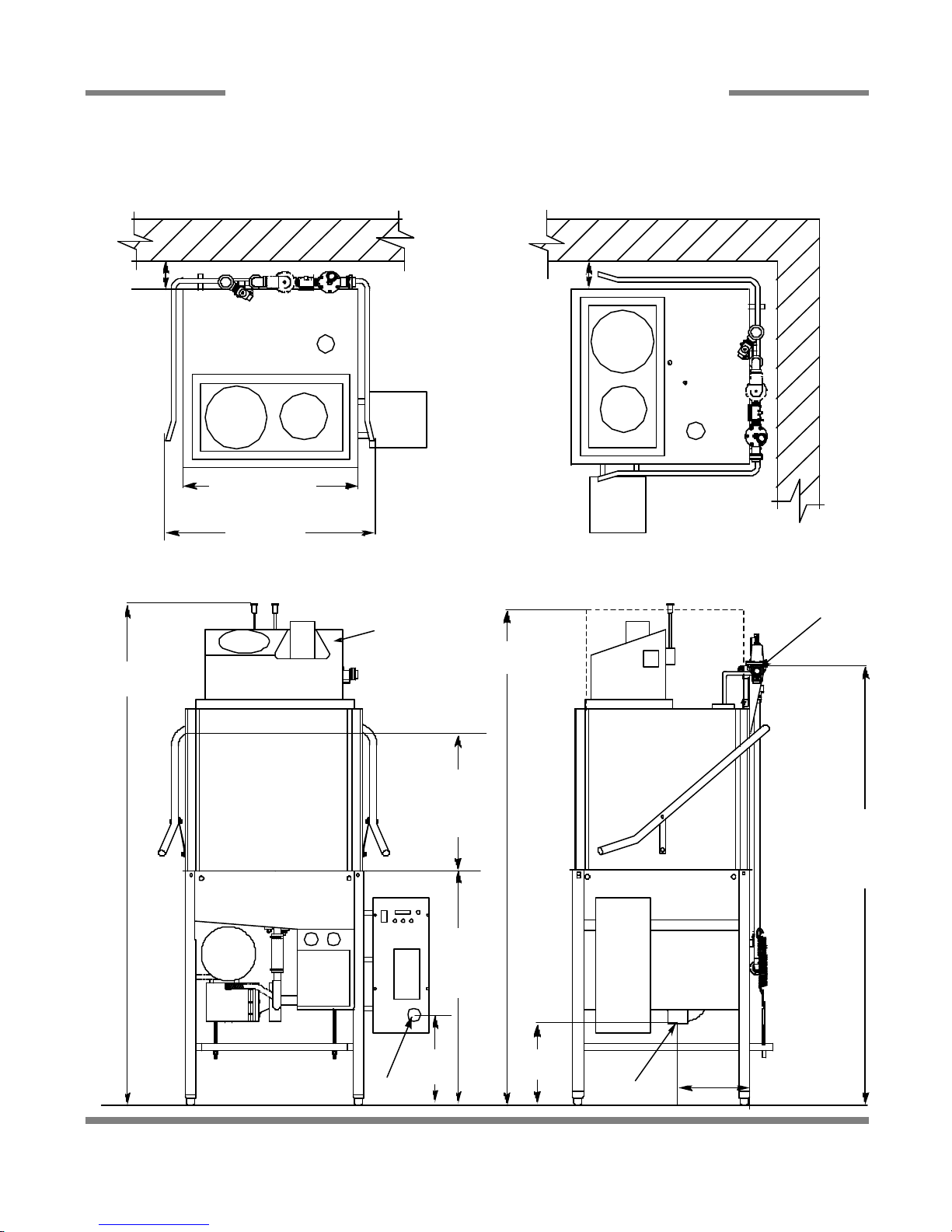
DIMENSIONS TEMPSTAR/TEMPSTAR LT/NB (SIDE MOUNTED CONTROL BOX)
4
25 1/4” (64.1 cm)
32” (81.3 cm)
17 1/2” (44.5 cm)
MACHINE
OPENING
10 5/8”
(27 cm)
34” (86.4 cm)
TABLE
HEIGHT
14 3/8”
(36.5 cm)
60 3/4” (154.3 cm)
WATER INLET TO
FLOOR
A- WATER INLET (3/4” NPT)
B-ELECTRICAL CONNECTION POINT C- DRAIN (1 1/2” NPT)
D- STANDARD CLEARANCE BETWEEN
MACHINE AND WALL (WITH DISHTABLE) IS 4” (10.2 cm).
D
A
B
D
C15 1/2”
(39.4 cm)
76” (193 cm)
W/ DOOR
OPEN
LEGEND:

Tempstar LT/NB/S/SDS Technical Manual 7610-011-86-35
Issued: 06-26-2006 Revised: N/A
SECTION 1: SPECIFICATION INFORMATION
DIMENSIONS TEMPSTAR/NB/LT/S (TOP MOUNTED CONTROL BOX)
5
25 1/4” (64.1 cm)
32” (81.3 cm)
17 1/2”
(44.5 cm)
MACHINE
OPENING
64 3/8”
(163.5 cm)
34” (86.4 cm)
TABLE
HEIGHT
76” (193 cm)
W/ DOOR OPEN
14 3/8”
(36.5 cm)
DRAIN
TO
FLOOR
61 3/4”
(156.8 cm)
WATER
INLET TO
FLOOR
60 5/8”
(154 cm)
A- WATER INLET (3/4” NPT)
B- ELECTRICAL CONNECTION POINT
C- DRAIN (1 1/2” NPT)
D- STANDARD CLEARANCE BETWEEN
MACHINE AND WALL (WITH DISHTABLE) IS 4” (10.2 cm).
D
A
B
B
D
C
15 1/2” (39.4 cm)
LEGEND
4 7/8” (12.4 cm)
Tempstar LT/NB/S/SDS Technical Manual 7610-011-86-35
Issued: 06-26-2006 Revised: N/A
SECTION 1: SPECIFICATION INFORMATION
DIMENSIONS TEMPSTAR SDS
6
25 1/4” (64.1 cm)
32” (81.3 cm)
74”
(188 cm)
17 1/2”
(44.5 cm)
MACHINE
OPENING
7 1/4”
(18.4 cm)
34”
(86.4 cm)
TABLE
HEIGHT
76” (193 cm)
W/ DOOR OPEN
14”
(35.6 cm)
60 3/4”
(154.3 cm)
WATER
INLET TO
FLOOR
A- WATER INLET (3/4” NPT)
B- ELECTRICAL CONNECTION POINT
C- DRAIN (1 1/2” NPT)
D- STANDARD CLEARANCE BETWEEN
MACHINE AND WALL (WITH DISHTABLE) IS 4” (10.2 cm).
E- CHEMICAL DISPENSING SYSTEM
D
A
B
D
E
C15 1/2” (39.4 cm)
Tempstar LT/NB/S/SDS Technical Manual 7610-011-86-35
Issued: 06-26-2006 Revised: N/A
SECTION 1: SPECIFICATION INFORMATION
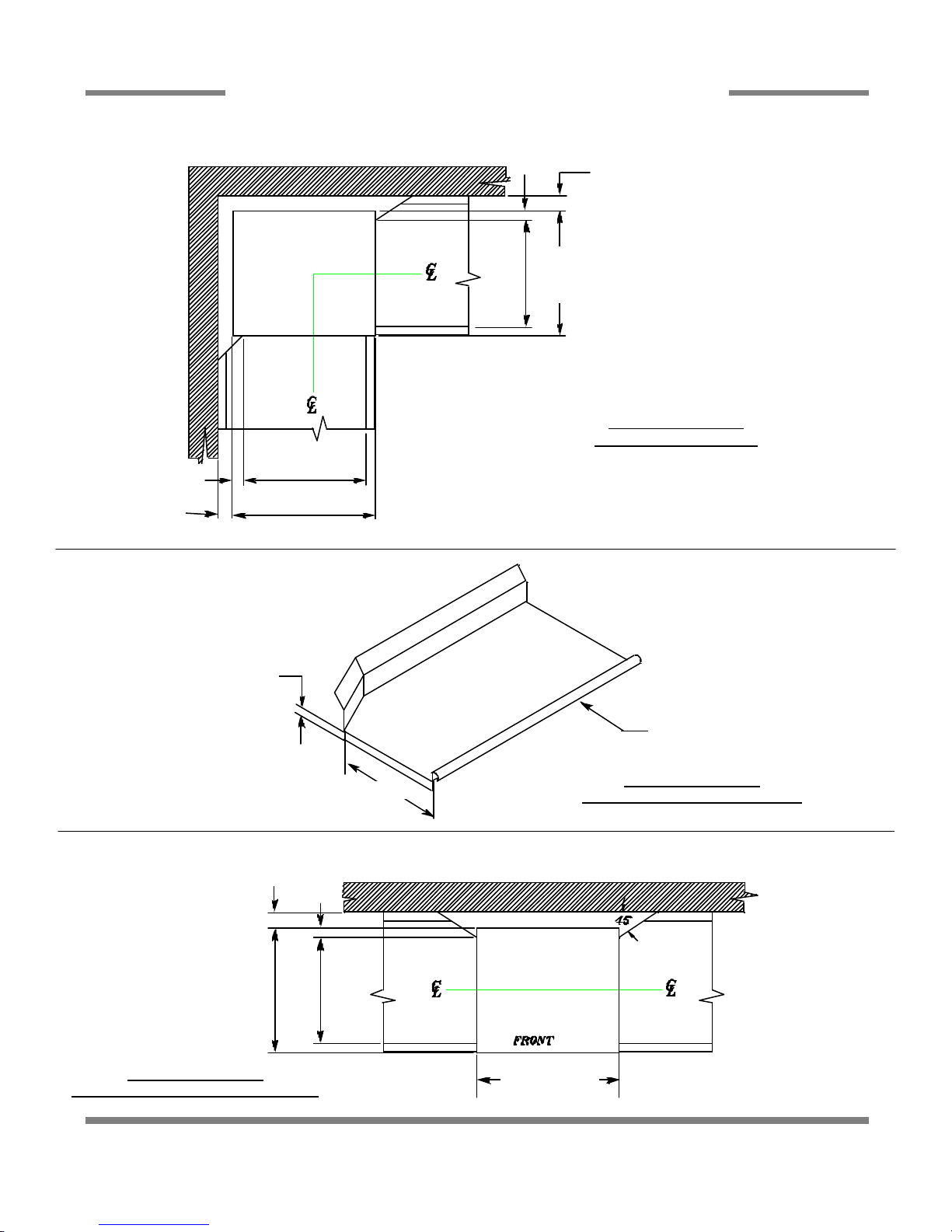
TABLE DIMENSIONS
7
TABLE DIMENSIONS
CORNER INSTALLATION
TABLE DIMENSIONS
CONNECTION TO DISHMACHINE
TABLE DIMENSIONS
STRAIGHT THROUGH INSTALLATION
20 1/2” (52.1 cm)
OPENING
25 1/4”
(64.1 cm)
2 1/2” (6.4 cm)
4” (10.2 cm)
MINIMUM
2 1/2”
(6.4 cm)
4” (10.2 cm)
MINIMUM
20 1/2” (52.1 cm)
OPENING
25 1/4”
(64.1 cm)
20 1/2” (52.1 cm)
3/4” (1.9 cm)
1 1/2” (3.81 cm) ROLL
4” (10.2 cm)
MINIMUM
2 1/2”
(6.4 cm)
25 1/4”
(64.1 cm)
20 1/2” (52.1 cm)
OPENING
25 1/4” (64.1 cm)

8
SECTION 2:
INSTALLATION/OPERATION
INSTRUCTIONS

VISUAL INSPECTION: Before installing the unit, check the container and machine for damage. A damaged container is an indi-
cator that there may be some damage to the machine. If there is damage to both the container and machine, do not throw away
the container. The dishmachine has been inspected and packed at the factory and is expected to arrive to you in new, undamaged
condition. However, rough handling by carriers or others may result in there being damage to the unit while in transit. If such a sit-
uation occurs, do not return the unit to Jackson; instead, contact the carrier and ask them to send a representative to the site to
inspect the damage to the unit and to complete an inspection report. You must contact the carrier within 48 hours of receiving the
machine. Also, contact the dealer through which you purchased the unit.
UNPACKING THE DISHMACHINE: Once the machine has been removed from the container, ensure that there are no missing
parts from the machine. This may not be obvious at first. If it is discovered that an item is missing, contact Jackson immediately to
have the missing item shipped to you.
LEVEL THE DISHMACHINE: The dishmachine is designed to operate while being level. This is important to prevent any damage
to the machine during operation and to ensure the best results when washing ware. The unit comes with adjustable bullet feet,
which can be turned using a pair of channel locks or by hand if the unit can be raised safely. Ensure that the unit is level from side
to side and from front to back before making any connections.
PLUMBING THE DISHMACHINE: All plumbing connections must comply with all applicable local, state, and national plumbing
codes. The plumber is responsible for ensuring that the incoming water line is thoroughly flushed prior to connecting it to any com-
ponent of the dishmachine. It is necessary to remove all foreign debris from the water line that may potentially get trapped in the
valves or cause an obstruction. Any valves that are fouled as a result of foreign matter left in the water line, and any expenses
resulting from this fouling, are not the responsibility of the manufacturer.
CONNECTING THE DRAIN LINE: The drain for the Tempstar models covered in this manual are gravity discharge drains. All pip-
ing from the 1 1/2” FNPT connection on the wash tank must be pitched (1/4” per foot) to the floor or sink drain. All piping from the
machine to the drain must be a minimum 1 1/2” I.P.S. and shall not be reduced. There must also be an air gap between the machine
drain line and the floor sink or drain. If a grease trap is required by code, it should have a flow capacity of 5 gallons per minute.
WATER SUPPLY CONNECTION: Ensure that you have read the section entitled “PLUMBING THE DISHMACHINE” above before
proceeding. Install the water supply line (3/4” pipe size minimum) to the dishmachine line strainer using copper pipe. It is recom-
mended that a water shut-off valve be installed in the water line between the main supply and the machine to allow access for ser-
vice.
The water supply line is to be capable of 20 A5 PSI “flow” pressure at the recommended temperature indicated on the data plate.
In areas where the water pressure fluctuates or is greater than the recommended pressure, it is suggested that a water pressure
regulator be installed. The Tempstar models covered in this manual come with water pressure regulators as standard equipment.
Please notify Jackson immediately if this component is not present on your machine.
Do not confuse static pressure with flow pressure. Static pressure is the line pressure in a “no flow” condition (all valves and ser-
vices are closed). Flow pressure is the pressure in the fill line when the fill valve is opened during the cycle.
It is also recommended that a shock absorber (not supplied with the Tempstar model) be installed in the incoming water line. This
prevents line hammer (hydraulic shock), induced by the solenoid valve as it operates, from causing damage to the equipment.
STEAM LINE CONNECTION: The steam machines come with lines by which the source steam needs to be connected. Connect
all steam lines to the machine as all applicable codes provide. See machine data plate for information concerning steam flow pres-
sure.
CHEMICAL DISPENSING EQUIPMENT: The Tempstar LT machine requires that a separate chemical feeder be connected to it to
provide the required detergent and sanitizer. This feeder needs to be able to operate against a head of 25 PSI and provide 1.79
ml of a 10% Chlorine sanitizer per minute.
PLUMBING CHECK: Slowly turn on the water supply to the machine after the incoming fill line and the drain line have been
installed. Check for any leaks and repair as required. All leaks must be repaired prior to placing the machine in operation.
Tempstar LT/NB/S/SDS Technical Manual 7610-011-86-35
Issued: 06-26-2006 Revised: N/A
SECTION 2: INSTALLATION/OPERATION INSTRUCTIONS
INSTALLATION INSTRUCTIONS
9

ELECTRICAL POWER CONNECTION: Electrical and grounding connections must comply with the applicable portions of the
National Electrical Code ANSI/NFPA 70 (latest edition) and/or other electrical codes.
Disconnect electrical power supply and place a tag at the disconnect switch to indicate that you are working on the circuit.
The dishmachine data plate is located on the right side and to the front of the machine. Refer to the data plate for machine oper-
ating requirements, machine voltage, total amperage load and serial number.
To install the incoming power lines, open the control box. This will require taking a phillipshead screwdriver and removing the four
(4) screws on the front cover of the control box. Install 3/4” conduit into the pre-punched holes in the back of the control box. Route
power wires and connect to power block and grounding lug. Install the service wires (L1, L2, and L3 (3 phase only)) to the appro-
priate terminals as they are marked on the terminal block. Install the grounding wire into the lug provided. Tighten the connections.
It is recommended that “DE-OX” or another similar anti-oxidation agent be used on all power connections.
VOLTAGE CHECK: Ensure that the power switch is in the OFF position and apply power to the dishmachine. Check the incom-
ing power at the terminal block and ensure it corresponds to the voltage listed on the data plate. If not, contact a qualified ser-
vice agency to examine the problem. Do not run the dishmachine if the voltage is too high or too low. Shut off the service break-
er and mark it as being for the dishmachine. Advise all proper personnel of any problems and of the location of the service
breaker. Replace the control box cover and tighten down the screws.
Tempstar LT/NB/S/SDS Technical Manual 7610-011-86-35
Issued: 06-26-2006 Revised: N/A
SECTION 2: INSTALLATION/OPERATION INSTRUCTIONS
INSTALLATION INSTRUCTIONS (CONTINUED)
10

PREPARATION: Before proceeding with the start-up of the unit, verify the following:
1. The pan strainer and pump suction strainer are in place and are clean.
2. The overflow tube and o-ring are installed.
3. That the wash and rinse arms are screwed securely into place and that their endcaps are tight. The wash and rinse
arms should rotate freely.
POWER UP: To energize the unit, turn on the power at the service breaker. The voltage should have been previously verified
as being correct. If not, the voltage will have to be verified.
FILLING THE WASH TUB: Ensure that the delime switch is in the NORMAL position, and place the power switch into the ON
position. The Tempstar should fill automatically and shut off when the appropriate level is reached (just below the pan strain-
er). Verify that the drain stopper is preventing the wash tub water from leaking excessively. There may be some slight leakage
from the drain hole. Verify that there are no other leaks on the unit before proceeding any further. The wash tub must be com-
pletely filled before operating the wash pump to prevent damage to the component. Once the wash tub is filled, the unit is ready
for operation.
WARE PREPARATION: Proper preparation of ware will help ensure good results and less re-washes. If not done properly, ware
may not come out clean and the efficiency of the dishmachine will be reduced. It is important to remember that a dishmachine
is not a garbage disposal and that simply throwing unscraped dishes into the machine simply defeats the purpose altogether
of washing the ware. Scraps should be removed from ware prior to being loaded into a rack. Pre-rinsing and pre-soaking are
good ideas, especially for silverware and casserole dishes. Place cups and glasses upside down in racks so that they do not
hold water during the cycle. The dishmachine is meant not only to clean, but to sanitize as well, to destroy all of the bacteria
that could be harmful to human beings. In order to do this, ware must be properly prepared prior to being placed in the machine.
DAILY MACHINE PREPARATION: Refer to the section entitled “PREPARATION” at the top of this page and follow the instruc-
tions there. Afterwards, check that all of the chemical levels are correct and/or that there is plenty of detergent available for the
expected workload.
WARM-UP CYCLES: For a typical daily start-up, it may be necessary to run the machine through 3 cycles to ensure that all of
the cold water is out of the system and to verify that the unit is operating correctly. To cycle the machine, ensure that the power
is on and that the tub has filled to the correct level. Lift the doors and the cycle light will illuminate. When the light goes out,
close the doors, the unit will start, run through the cycle, and shut off automatically. Repeat this two more times. The unit should
now be ready to proceed with the washing of ware.
WASHING A RACK OF WARE: To wash a rack, open the doors completely (being careful for hot water that may drip from the
doors) and slide the rack into the unit.
Close the doors and the unit will start automatically. Once the cycle is completed, open the door (again watching for the drip-
ping hot water) and remove the rack of clean ware. Replace with a rack of soiled ware and close the doors. The process will
then repeat itself.
OPERATIONAL INSPECTION: Based upon usage, the pan strainer may become clogged with soil and debris as the workday
progresses. Operators should regularly inspect the pan strainer to ensure it has not become clogged. If the strainer does, it will
reduce the washing capability of the machine. Instruct operators to clean out the pan strainer at regular intervals or as required
by work load.
SHUTDOWN AND CLEANING: At the end of the workday, close the doors. When the unit completes the cycle, turn the power
switch to the OFF position and open the doors. Remove and clean the pan strainer. Remove the drain stopper from the tub and
allow the tub to drain (NOTE: the wash tank water will be hot so caution is advised). Once the wash tub is drained, remove the
pump suction strainer. Remove soil and debris from the strainer and set to the side. Unscrew the wash and rinse arms from
their manifolds. Remove the endcaps and flush the arms with water. Use a brush to clean out the inside of the arms. If the noz-
zles appear to be clogged, use a toothpick to remove the obstruction. Wipe the inside of the unit out, removing all soil and
scraps. Reassembly the wash and rinse arms and replace them in the unit. The arms only need to be hand tight, do not use
tools to tighten them down. Reinstall the drain stopper and strainers and close the doors.
Tempstar LT/NB/S/SDS Technical Manual 7610-011-86-35
Issued: 06-26-2006 Revised: N/A
SECTION 2: INSTALLATION/OPERATION INSTRUCTIONS
OPERATION INSTRUCTIONS
11

Detergent usage and water hardness are two factors that contribute greatly to how efficiently your dishmachine will operate.
Using detergent in the proper amount can become, in time, a source of substantial savings. A qualified water treatment spe-
cialist can tell you what is needed for maximum efficiency from your detergent, but you should still know some basics so you’ll
understand what they are talking about.
First, you must understand that hard water greatly effects the performance of the dishmachine. Water hardness is the amount
of dissolved calcium and magnesium in the water supply. The more dissolved solids in the water, the greater the water hard-
ness. Hard water works against detergent, thereby causing the amount of detergent required for washing to increase. As you
use more detergent, your costs for operating the dishmachine will increase and the results will decrease. The solids in hard
water also may build-up as a scale on wash and rinse heaters, decreasing their ability to heat water. Water temperature is
important in removing soil and sanitizing dishes. If the water cannot get hot enough, your results may not be satisfactory. This
is why Jackson recommends that if you have installed the machine in an area with hard water, that you also install some type
of water treatment equipment to help remove the dissolved solids from the water before it gets to the dishmachine.
Second, hard water may have you adding drying agents to your operating cycle to prevent spotting, when the real problem is
deposited solids on your ware. As the water evaporates off of the ware, the solids will be left behind to form the spotting and
no amount of drying agent will prevent this. Again, using treated water will undoubtedly reduce the occurrences of this prob-
lem.
Third, treated water may not be suitable for use in other areas of your operation. For instance, coffee made with soft water may
have an acid or bitter flavor. It may only be feasible to install a small treatment unit for the water going into the dishmachine
itself. Discuss this option with your qualified water treatment specialist.
Even after the water hardness problems have been solved, there still must be proper training of dishmachine operators in how
much detergent is to be used per cycle. Talk with your water treatment specialist and detergent vendor and come up with a
complete training program for operators. Using too much detergent has as detrimental effects as using too little. The proper
amount of detergent must be used for job. It is important to remember that certain menu items may require extra detergent by
their nature and personnel need to be made aware of this. Experience in using the dishmachine under a variety of conditions,
along with good training in the operation of the machine, can go a long way in ensuring your dishmachine operates as effi-
ciently as possible.
Certain dishmachine models require that chemicals be provided for proper operation and sanitization. Some models even
require the installation of third-party chemical feeders to introduce those chemicals to the machine. Jackson does not recom-
mend or endorse any brand name of chemicals or chemical dispensing equipment. Contact your local chemical distributor for
questions concerning these subjects.
Some dishmachines come equipped with integral solid detergent dispensers. These dispensers are designed to accommodate
detergents in a certain sized container. If you have such a unit, remember to explain this to your chemical distributor upon first
contacting them.
As explained before, water temperature is an important factor in ensuring that your dishmachine functions properly. The data
plate located on each unit details what the minimum temperatures must be for either the incoming water supply, the wash tank
and the rinse tank, depending on what model of dishmachine you have installed. These temperatures may also be followed by
temperatures that Jackson recommends to ensure the highest performance from you dishmachine. However, if the minimum
requirements are not met, the chances are your dishes will not be clean or sanitized. Remember, a dish can look clean, but it
may not be sanitized. Instruct your dishmachine operators to observe the required temperatures and to report when they fall
below the minimum allowed. A loss of temperature can indicate a much larger problem such as a failed heater or it could also
indicate that the hot water heater for your operation is not up to capacity and a larger one may need to be installed.
There are several factors to consider when installing your dishmachine to ensure that you get the best possible results from it
and that it operates at peak efficiency for many years. Discuss your concerns with your local chemical distributor and water
treatment specialist before there is a problem.
Tempstar LT/NB/S/SDS Technical Manual 7610-011-86-35
Issued: 06-26-2006 Revised: N/A
SECTION 2: INSTALLATION/OPERATION INSTRUCTIONS
DETERGENT CONTROL
12

13
SECTION 3:
PREVENTATIVE MAINTENANCE

The dishmachines covered in this manual are designed to operate with a minimum of interaction with the operator. However,
this does not mean that some items will not wear out in time. Jackson highly recommends that any maintenance and repairs
not specifically discussed in this manual should be performed by QUALIFIED SERVICE PERSONNEL ONLY. Performing main-
tenance on your dishmachine may void your warranty if it is still in effect, so if you have a question or concern, do not hesitate
to contact one of the QUALIFIED SERVICE AGENCIES listed in the back of this manual.
There are many things that operators can do to prevent catastrophic damage to the dishmachine. One of the major causes of
component failure has to do with prescrapping procedures. A dishmachine is not a garbage disposal; any large pieces of mate-
rial that are put into the machine shall remain in the machine until they are either broken up (after spreading out on your ware!)
or physically removed. Strainers are installed to help catch debris, but they do no good if they are clogged. Have operators reg-
ularly inspect the pan strainers to ensure (1) that they are free of soil and debris and (2) they are laying flat in the tub.
When cleaning out strainers, do NOT beat them on waste cans. The strainers are made of metal and can be forgiving; but once
severe damage is done, it is next to impossible for the strainer to work in the way it was designed to. Wipe out strainers with
a rag and rinse under a faucet if necessary. For stubborn debris, a toothpick should be able to dislodge any obstructions from
the perforations. Always ensure that strainers are placed back in the machine before operation and that they lay flat in the tub.
You may wish to learn more about how your water hardness will effect the performance of your machine. Hard water makes
dishmachines work harder and decreases efficiency.
Again, it is important to remind operators that trying to perform corrective maintenance on the dishmachine could lead to larg-
er problems or even cause harm to the operator. If a problem is discovered; secure the dishmachine using proper shut down
procedures as listed in this manual and contact a QUALIFIED SERVICE AGENCY.
Some problems, however, may having nothing to do with the machine itself and no amount of preventative maintanence is
going to help. A common problem has to do with temperatures being too low. Verify that the water temperatures coming to your
dishmachine match the requirements listed on the machine data plate. There can be a variety of reasons why your water tem-
perature could be too low and you should discuss it with a QUALIFIED SERVICE AGENCY to determine what can be done.
By following the operating and cleaning instructions in this manual, you should get the most efficient results from your machine.
As a reminder, here are some steps to take to ensure that you are using the dishmachine the way it was designed to work:
1. Ensure that the water temperatures match those listed on the machine data plate.
2. Ensure that all strainers are in place before operating the machine.
3. Ensure that all wash and/or rinse arms are secure in the machine before operating.
4. Ensure that drains are closed/sealed before operating.
5. Remove as much soil from dishes by hand as possible before loading into racks.
6. Do not overfill racks.
7. Ensure that glasses are placed upside down in the rack.
8. Ensure that all chemicals being injected to machine have been verified as being at the correct concentrations.
9. Clean out the machine at the end of every workday as per the instructions in the manual.
10. Always contact a QUALIFIED SERVICE AGENCY whenever a serious problem arises.
11. Follow all safety procedures, whether listed in this manual or put forth by local, state or national codes/regulations.
Tempstar LT/NB/S/SDS Technical Manual 7610-011-86-35
Issued: 06-26-2006 Revised: N/A
SECTION 3: PREVENTATIVE MAINTENANCE
PREVENTATIVE MAINTENANCE
14
This manual suits for next models
4
Table of contents
Other Enodis Dishwasher manuals


