Enovation Controls MURPHY HelmView HV780 User manual

00-02-0882
2015-09-26
Section 78
HelmView
ModelHV780
InstallationManual

In order to consistently bring you the highest quality, full-featured products, we reserve the right to change our
specifications and designs at any time. The latest version of this manual can be found at enovationcontrols.com.
BEFORE BEGINNING INSTALLATION OR OPERATION OF THIS
MURPHY PRODUCT:
Read and follow all installation/operation instructions.
Please contact Enovation Controls immediately if you have any
questions.

Table of Contents
Hardware Installation.................................................................................................................1
Inspecting Package Contents.......................................................................................1
Dash-Mounted Installation............................................................................................1
Wiring Information.....................................................................................................................3
Pinout Specifications....................................................................................................3
Wiring Schematic.........................................................................................................4
Specifications.............................................................................................................................6

THIS PAGE INTENTIONALLY LEFT BLANK

Section 78 00-02-0882
2019-09-26 - 1 -
Hardware Installation
The following instructions will guide you through installing the HelmView HV780 display.
Inspecting Package Contents
Before attempting to install the product, it is recommended that you ensure all parts are
accounted for and inspect each item for damage (which sometimes occurs during shipping).
The items included in the box are:
HV780 unit
Installation kit –P/N 78-00-0638 includes:
4 ea. machine screws and flat washers
4 Nylock nuts
Installation manual –P/N 00-02-0882
Operations manual –P/N 00-02-0883
Dash-Mounted Installation
Tools needed.
Drill with 5/32” size bit
Jigsaw
Wrench or socket 6-32 Nylock nuts (provided) to studs
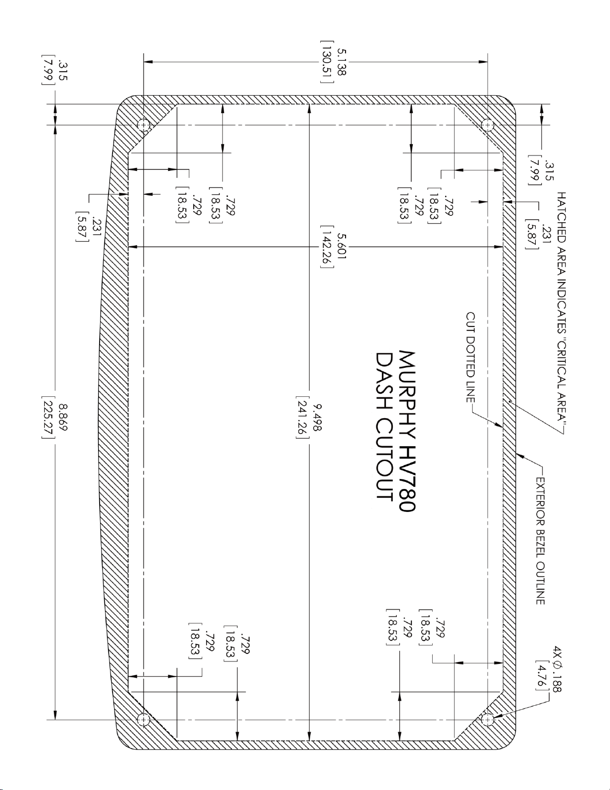
Preparing the Dash
Determine the location of the HelmView in the dash. Use the Installation Template (included at
the end of the manual) as a guideline to cut a hole in the dash to the specified dimensions.
Drill holes where indicated on the template for the mounting screws.
NOTE: If you downloaded this document from the Murphy website, be aware
that the template pdf file may not automatically print to scale. When submitting
the file for print, you will need to select None for Page Scaling. Check the
accuracy of the printed template by verifying the measurements labeled on the
template are correct.
If this manual was supplied with your product, the template will be correct.

Section 78 00-02-0882
2019-09-26 - 2 -
Mounting the Unit
1. Place the back side of the display through the opening in the dash.
2. Use the four screws to line up the unit with the drilled holes.
3. Push the unit through the opening and screws through the drilled holes until the back of
the case is flush.
4. Use the Nylock nuts provided to tighten unit to the dash. Use the appropriate wrench or
socket to tighten. Torque lock nuts to 8-10 inch pounds.
Flush Mounting the Dash
1. Cut the dash to allow for the display without bezel. Ensure enough of the material is
available to properly secure the display within the dash.
2. Place the display behind dash and line up the four mounting holes on the display with
the holes in dash.
3. Install four bolts and torque the 6-32 Nylock nuts to 5 inch pounds.

Section 78 00-02-0882
2019-09-26 - 3 -
Wiring Information
Pinout Specifications
Signal Definitions
CAN: 3 ports according to CAN specification 2: 1 port isolated according to NMEA 2000 USB
2.0 host Video input (optional): NTSC/PAL Inputs (3) 0-5 VDC analog inputs, (1) input
configurable to support measurement frequencies from 2 Hz - 10kHz values from 0-100% duty
cycle Output: Digital, capable of sinking 500mA.

Section 78 00-02-0882
2019-09-26 - 4 -
Wiring Schematic –Black Connector
WARNING: Failure to install the unit per the specified wiring diagrams may cause
damage to the unit. DO NOT connect power to the video ground. Warranty is void
for damage caused by incorrect wiring.

Section 78 00-02-0882
2019-09-26 - 5 -
Wiring Schematic –Gray Connector
WARNING: Failure to install the unit per the specified wiring diagrams may cause
damage to the unit. DO NOT connect power to the video ground. Warranty is void
for damage caused by incorrect wiring.

Section 78 00-02-0882
2019-09-26 - 6 -
Specifications
Electrical
Display
7” / 178mm color transmissive TFT LCD
Resolution
WVGA, 800 x 480 pixels, 16-bit color
Aspect Ratio
16:9
Orientation
Landscape
Backlighting
LED, 1000 nit maximum brightness
Contrast
400:1
Refresh Rate
60 Hz
Microprocessor
Freescale™ i.MX357, 32bit, 532 MHz, ARM 11 core
Operating System
QNX® Real-time Operating system
Flash Memory
2 GB, 1 GB available for data logging
RAM
128 Mbytes SRAM
Clock
Real-time clock with rechargeable Li-ion battery
Operating Voltage
6 - 36 VDC, reverse polarity protected
Power Consumption
10 W full backlight
22 W full backlight with heater (< -10º C)
Communication
2) CAN 2.0B with one isolated (NMEA compliant);
(1) RS-485 serial (MODBus master/slave)
RS-485
1 MODBUS Master / Slave port, PVA
Protocols
J1939, NMEA 2000 (GPS)
Connection
(2) AMPSEAL 23pin (AMP 770680-1 and AMP 770680-4)
Keyboard
10 tactile pushbuttons
USB
(1) USB 2.0 host (OTG, full speed)
Inputs
(3) 0-5V, 4-20mA, or resistive Analog 0-5V, Analog 4-20 mA, Analog
resistive, Digital 0-5V, Digital Active Low
(1) Frequency In (20Hz - 10 kHz), 5Vpk-pk.min
Video Input
3 NTSC/PAL, individually viewable
Output
(1) 500mA; switched low-side, (1) Frequency Out (0Hz - 5 kHz),
120Vpk-pk max Vbat rms square wave
SD Storage
For program updates
Landscape or Portrait
Mounting Options
Gimbal, Front Panel or Back Mount

Section 78 00-02-0882
2019-09-26 - 7 -
Environmental
Operating Temperature
-40º C to +85º C
Storage Temperature
-40º C to +85º C
Protection
IP66 and 67, front and back
Emissions
IEC 60945, 95/54/EC
Immunity
SAE J1113
Vibration
Random vibration, 7.86 Grms (5-2000Hz), 3 axis
Shock
± 50G in 3 axes
Mechanical
Dimensions
9.75 x 6.23 in. (247.7 x 158.2mm) landscape
Unit Depth –2.58 in (65.49mm)
Shipping Weight
Approximately 2.5 lbs. (1.13 kg)
Case Material
PC/ABS

Section 78 00-02-0882
2019-09-26 - 8 -

THIS PAGE INTENTIONALLY LEFT BLANK

THIS PAGE INTENTIONALLY LEFT BLANK

This manual suits for next models
1
Table of contents


