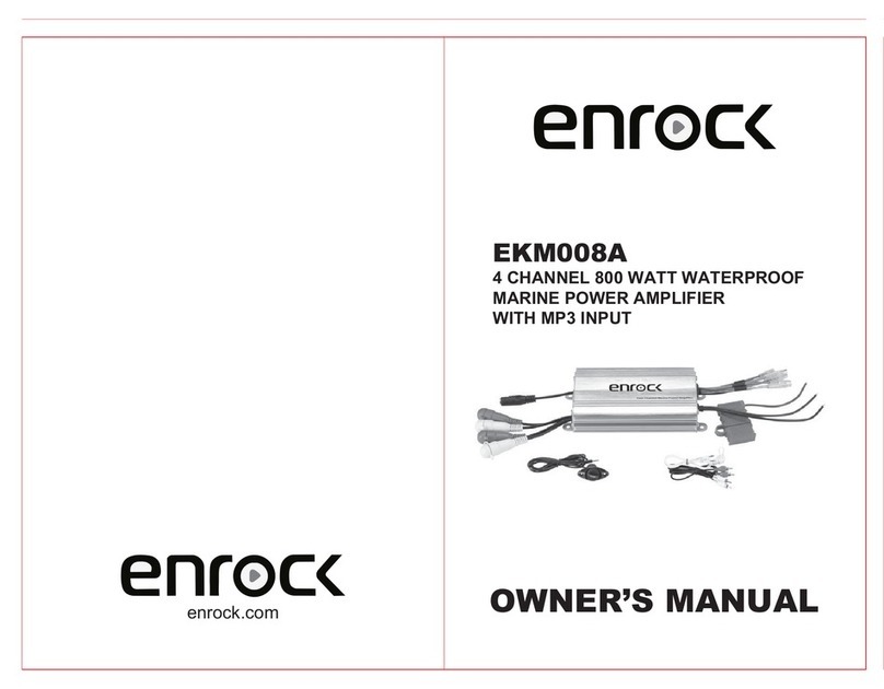
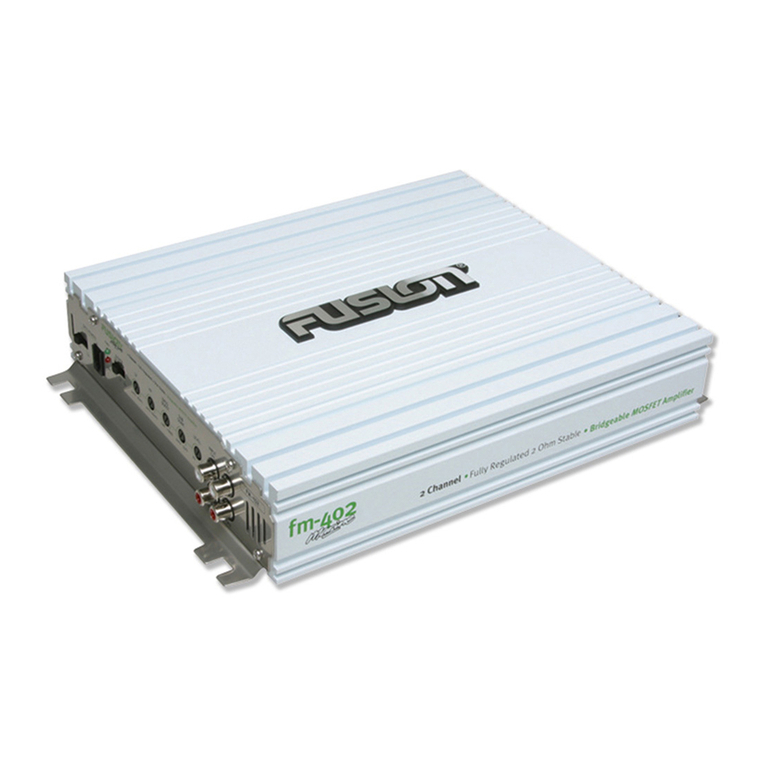
Enrock EEA720.4 Installation instructions

EEA720.4
4-Channel Power Amplifier
INSTALLATION / OWNER’S MANUAL
EEA720.4
4-Channel Power Amplifier
INSTALLATION / OWNER’S MANUAL

EEA720.4
The Enrock multipurpose amplifier is designed to delivery accurate
and high functioning sound. It is intended for multiple uses.
Weather resistant for boat or marine application
Durable and powerful for car use
Compact and rugged for off-road motorcycle installation
Features:
Sealed chassis for use in harsh environments
Ultra-Efficient full range class D operation
High and Low Level Inputs – Connects with any system
Built-in crossover – Maximum Flexibility
2 or 4 channel input – easy installation
Stainless steel and aluminum hard wire
Specifications:
RMS Power at 4ohm: 4x45W
RMS Power at 2ohm: 4 x 60W
Bridged Power at 4ohms: 2 x 120W
Total Harmonic Distortion: <0.5% (4ohms)
Signal to Noise ratio: 97dB
High pass filter: 120Hz/80Hz/Off
Input Range: 200mV-10V
Frequency Response: 20Hz to 20KHz
Dimensions: 8.75” x 4” x 1.75”
Installation Precautions:
Professional installation is always highly recommended. The performance of
your new amp may not be satisfactory. Installation by a nonprofessional
may compromise the product functions.
Amplifiers are generally mounted in the hatch/trunk area or under the seat
of your vehicle. In boats or off-road vehicles, under the seat is an acceptable
location. Although the EMA4720 has coated circuit board to resist corrosion
from humidity and dampness, be sure to choose a mounting location that
will avoid direct contact with water. Choose a location that will deliver
sufficient ventilation for the amplifier. The fins should be facing upwards;
either vertically or horizontally. Be sure to secure the amplifier with the
provided screws.
Warnings
Before securing the amplifier examine the mounting location cautiously to
ensure that you do not drill into or damage any electrical, hydraulic,
fluid or fuel lines.
Always check your speaker load with a multi-meter before connecting the
amplifier. Connecting any speaker load lower than the rated impedance of
the amplifier will result in damage to the amplifier. Such damage is not
covered under the warranty, so pay attention to what connections are done
to the amplifier

Functions:
Input Mode Switches
The EMA4720 hosts two convenient working modes. When the switch’s position is set as
below, the unit can work as a 2 channel amplifier or a 4 channel amplifier
Front/Rear X-Over
The EMA4720 supplies 3 fixed crossover frequency settings (HPF) through every four-way
switch for front channel and reach channel. Switch the position and the related crossover
frequency as the drawing below.
Low (RCA) High Level Input
The amplifier is equipped with two types of inputs through a water proof cable with MOLEX
connectors. You can choose to connect two different ways, RCA cable or high input cable to
get RCA input or high input.
Front/Rear Sensitivity Control
Two Controls in the end panel can supply an independent level control for reach channel and
front channel
Water Proof Rubber Cover Mounting Hole
Place the outstanding stick into the mounting hole. The rubber cover can be affixed to the
panel to cover all the switches and holes thereby resulting it suitable for waterproof use
PWR/PRT Indicator
The light is dual color LED indicator for power and protection indicator
Power Indicator: Blue, when the unit is powered on
Protection Indicator: Red, When the unit goes into protect mode
Power Input Cable
A three wired cable with three pin connectors in a black cable strain holder
1. Yellow: +12V
2. Black: Ground
3. Blue: Remote In
Speaker Output Cable
An eight wire cable with eight pin connectors in a black cable strain holder
1: White: Front Output Left –
2: White/Black: Front Output Left +
3: Gray: Front Output Right +
4: Gray/Black: Front Output Right -
5: Green: Rear Output Left –
6: Green/Black: Rear Output Left +
7: Violet: Rear Output Right +
8: Violet/Black: Rear Output Right -
1.
2.
3.
4.
5.
6.
7.
8.
PP WW RR
PP RR TT
86 7
SS EE NN SS
RR EE AA RR SS EE NN SS
FF RR OO NN TT
XX -- OO VV EE RR
MM OO DD EE
XX -- OO VV EE RR
MM II NN MM AA XX
RR EE AA RR FF RR OO NN TT
MM II NN MM AA XX
II NN PP UU TT
34 42 215
EEA720.4

Troubleshooting:
Refer to the list below and follow the suggested procedures. Speakers and
speaker wires/connections should be tested first.
No Output:
Confirm that all wiring is firmly connected.
Both +12V and REM terminals must have +12volts present and GND must
be connected to chassis ground or the negative terminal of the battery
Confirm that signal source is connected and is supplying output signals.
To confirm that the amp is working, connect an RCA patch cord to the
line inputs of the amplifier (do not connect the other end of the patch
cord). Briefly tap the center pin of each (disconnected) RCA plug on the
other (disconnected) end with your finger. This action should produce a
noise (brief static or hum) in the speakers.
If the amp is hot, check the speaker impedance or load. The total
minimum impedance of all speakers should not be lower than the ratings
of the amp.
Weak output:
Check gain control adjustment
Check speaker impedance
Noise in Audio:
Speaker and input wires should never be routed next to wires that
interconnect lights and other accessories/equipment in the vehicle.
Rerouting of these wires can often reduce noise.
A ‘clicking’ or ‘popping’ noise at a rate that follows engine speed is often
induced by the vehicles ignition system. Confirm that the vehicle is
equipped with resistor spark plugs and wires. The ignition system may
need service.
If the noise is a ‘whine’ that goes up or down with engine speed, confirm
that the amp and source unit is properly grounded.
If above suggestions do not improve or reduce noise interference, the
system should be checked by a professional installer.
A.
B.
C.
D.
A.
B.
A.
B.
C.
D.
SS EE NNSS
RR EE AA RR SS EE NN SS
FF RR OO NN TT
XX -- OO VV EE RR
MM OO DD EE
XX -- OO VV EE RR
MM IINN MM AA XX
RR EE AA RR FF RR OO NN TT
MM IINN MM AA XX
IINN PP UU TT
Low Level Input Wiring
Power Input Wiring
EEA720.4

Speaker Output Wiring Limited One Year Warranty
This warranty gives you specific legal rights. You may also have other rights which vary from state
to state.
Enrock warrants this product to the original purchaser to be free from defects in material and
workmanship for a period of one year from the date of the original purchase.
Enrock agrees, at our option, during the warranty period, to repair any defect in material or
workmanship or to furnish an equal new, renewed or comparable product (whichever is deemed
necessary) in exchange without charges, subject to verification of the defect or malfunction and
proof of the date of purchase. Subsequent replacement products are warranted for the balance of
the original warranty period.
Who is covered? This warranty is extended to the original retail purchaser for products purchased
and used in the U.S.A. What is covered? This warranty covers all defects in material and workman-
ship in this product. The following are not covered: installation/removal costs, damage resulting
from accident, misuse, abuse, neglect, product modification, improper installation, incorrect line
voltage, unauthorized repair or failure to follow instructions supplied with the product, or damage
occurring during return shipment of the product.
What to do?
Before you call for service, check the troubleshooting guide in your owner’s manual. A slight
adjustment of any custom controls or connections discussed in your instruction booklet may
save you a service call.
If you require service during the warranty period, you must carefully pack the product
(preferably in the original package) and ship it by prepaid transportation with a copy of the
original receipt from the retailer to an authorized service center.
Please describe your problem in writing and include your name, a USA return shipping address
(P.O. Box not acceptable), and a daytime phone number with your shipment.
For more information and for the location of the nearest authorized service center please
contact us by one of the following methods:
Call us toll-free at 1-844-336-7625
Exclusion of Certain Damages: This warranty is exclusive and in lieu of any and all other
warranties, expressed or implied, including without limitation the implied warranties
of merchantability and fitness for a particular purpose and any obligation, liability, right, claim or
remedy in contract or tort, whether or not arising from the company’s negligence, actual or
imputed. No person or representative is authorized to assume for the company any other liability
in connection with the sale of this product. In no event shall the company be liable for indirect,
incidental or consequential damages.
1.
2.
3.
4.
EEA720.4
Table of contents
Other Enrock Amplifier manuals
