Enrock EC1865BM Operating instructions

EC1865BM
INSTALLATION/OWNER’S MANUAL
6.5” 2-Way Car Speakers
EM1865BM
6.5” 2-Way Car Speakers
Installation / Owner’s Manual
Thank you for purchasing this Enrock 6.5” 2-Way Speakers
Please read through these instructions carefully so you will know
how to operate your model properly.
Keep these instructions in a safe place for future references.
LIMITED WARRANTY
Enrock warrants this product to be free from defects in material
andworkmanship for a period of 90 days from purchase. The Enrock product
is sold with the understanding that the purchaser has
independentlydetermined the suitability of this product. This warranty is
offered to the original purchaser of the product only. This warranty does not
cover the product if physically damaged, subject to negligence or misuse,
abuse, alteration, accident, or an act of GOD. This warranty does not apply to
product which has water or physically damaged by accident or which has
been misused, disassembled or altered.The original dated sales slip or proof
of purchase will establish warrantyeligibility. If the product should prove
defective within the warranty period, return the product with proof of
purchase to Enrock. Enrock, at its option, will replace or repair the product
free of charge and return the product.In no event shall Enrock be responsi-
ble for claims beyond the replacement value of the defective products or in
any way be liable or responsible for consequential or incidental damages. No
implied warranties, whether for fitness or any particular use or otherwise,
except as set forth above (which is made expressly in lieu of all other
warranties) shall apply to products sold by Enrock. Enrock cannot be held
responsible fordiscrepancies/inconsistencies that may occur due to
automotivemanufacturing changes or option.

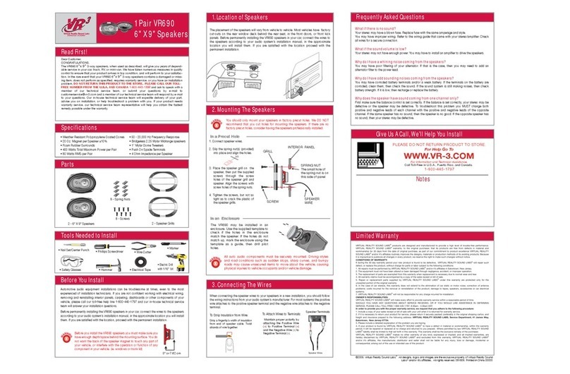
SUGGESTED MOUNTING POSITIONS:
The EC1865BM can be mounted in three different configurations. Always
double check for mounting depth limitations, never cut before you check.
PRIOR TO INSTALLING THIS PRODUCT:
Inspect your speaker before beginning installation. Notify your Enrock dealer if you
notice any damaged parts. Hold on to the box as well as packaging material in case it
needs to be transported.
Speaker damage can occur when an amplifier is made to play at higher listening
levels than it can produce at low distortion levels. A speaker will get damaged when
trying to get too much volume from a low-powered amplifier or receiver than from a
high powered one.
To avoid potential shorts in the electrical system, be sure to disconnect the (-) battery
cable before installation. Use this unit with a 12-volt battery and negative grounding
only.
When replacing a fuse, be sure to only use a fuse of the rating specified on this
product.
To avoid short-circuiting, cover any disconnected leads with insulating tape. It is
especially important to insulate any unused wires, which if left
uncovered may cause a short circuit. When connecting other devices to this product,
refer to the manual for the product to be connected. The black cable is ground, make
sure to connect the ground wire first.
Ensure that the ground cable is properly connected to metal parts of the vehicles
body frame or direct to the battery, if your vehicle does not have a grounded chassis
frame. The ground cable of this unit’s power amp and a second powered system
must be connected to the frame separately with different screws. If the screw for the
ground wire loosens or falls out, it could result in fire or malfunction
EC1865BM
GROUND CABLE
METAL FRAME
YOUR AMPLIFIER
SPEAKER 1
SPEAKER 2
+
-
+
-
+12V BATTERY YELLOW
REMOTE OUT
+12V BLUE
CHASSIS
GROUND
POINT
BATTERY
OPTIONAL DIRECT BATTERY WIRING CIRCUIT
BLACK
OPTIONAL
FUSE AND FUSE HOLDER
(NOT INCLUDED)
CHASSIS
GROUND
POINT
Normally Open
ON/OFF ACC switch
YOUR
BATTERY
KILL SWITCH
YOUR RADIO
STRIPPED WIRE NEGATIVE
12FT

FLUSH MOUNT INSTALLATION
Tweeter Mounting:
1. Check for suitable mounting depth.
2. Mark the center of the spot and cut a 2” diameter hole using a hole saw
or drill bit.
3. Assemble the cup, clamp and machine screw loosely as shown.
4. Route wires through the round opening in the bottom of the cup
5. Press the assembly in the 2” diameter hole until the clamp edge is below
the mounting surface, then tighten the screws.
6. Connect wires form the tweeter terminals of the crossover to the
tweeteritself. Connect the red wire from the (+) terminal of the crossover
tweeter output to the red (+) wire from the tweeter.
7. Mount the tweeter by snapping it into the mounting cup.
SURFACE MOUNT INSTALLATION:
Tweeter Mounting:
1. Using the base of the surface mount cup as a template, mark the
screw-hole and drill them using a ½” drill bit. Drill a second hole for the
speaker wiring using a 3/16” drill bit.
2. Screw surface mount cup to the panel.
3. Push the tweeter wires through the open area at the bottom of the cup
and through the hole in the panel
4. Connect wires from the tweeter terminals of the crossover to the tweeter
wires. Be sure to connect the red wire strand from the tweeter to the (+)
terminal of the crossover tweeter output.
5. Mount the tweeter by snapping it into the mounting cup.
EC1865BM
INSTALLATION INSTALLATION

PACKAGE CONTENTS:
6.5” 2-Way Speakers (2)
Speaker Wire & Mounting Hardware Kit (2)
User Manual / Warranty Card (1)
WHAT YOU NEED TO REMEMBER:
SAFETY PROVISIONS:
Turning up the volume too high may cause you not to hear what’s around you.
Avoid playing your music at the highest level.
Use caution in possibly dangerous situations
Do not operate mobile video equipment while driving a vehicle
Start your volume control level at a low level and slowly turn up the volume to a
comfortable listening level without ear discomfort or distortion.
Immediately turn the power of and consult an installation expert if you notice
strange noises, smoke or odor from this product. Continued use of a faulty unit
may cause permanent damage to your system.
INSTALLATIO PROVISIONS:
Always consult with a qualified installer
Use only the installation parts provided with the speaker
When wiring directly to the vehicles battery, be sure to disconnect the batteries
negative terminal wire before starting any wiring procedures. If extending the main
power wire, it is suggested that an optional fuse and fuse holder (not included)
with minimum rating of 10 amperes be in-line with the positive battery terminal.
The ground cable length should not exceed 18-inches
Do not attempt to install or service this product by yourself. Installation or
servicing of this product by persons without professional training and experience
in electronic equipment and motorized vehicle accessories may be dangerous and
could expose you to the risk of electric shock, injury or other hazards.
EC1865BM
