manuals.online logo
Brands
  1. Home
  2. •
  3. Brands
  4. •
  5. Vibe
  6. •
  7. Car Speakers
  8. •
  9. Vibe OPTIVWT5-V8 Configuration guide

Vibe OPTIVWT5-V8 Configuration guide

OPTIVWT5-V8
OPTI8VWT5-V0
OPTI8VWT5.1-V0
Volkswagen Transporter T5 & T5.1 (2003-2015)
OPTIVWT6-V9
OPTI8VWT6-V0
Volkswagen Transporter T6 (upto 2019)
OPTIVWT6.1-V0 6.5”VERSION ONLY
VEHICLE SPECIFIC AUDIO UPGRADES
High Efficiency OEM Speaker System
Introduction
Volkswagen Transporter T5 & T5.1 (2003-2015)
Volkswagen Transporter T6 & (2015-2019)
Volkswagen Transporter T6.1 (upto 2019) –6.5”ONLY
This VIBE Optisound speaker kit has been specifically designed as a direct speaker and
tweeter upgrade for the Volkswagen T5 & T5.1 & T6 & T6.1
Using super-efficient speaker technology combined with everything you need in one box,
upgrading your speakers and getting a massive improvement in sound and performance
couldn’t be easier. The kit includes all installation parts required, plus additional sound
enhancing components to give the best listening experience possible.
Using the 8”in your T5. Please note some T5 vehicle require the later larger T5.1
speaker adapter please check before installation which one you need.
Box Contents:
2 x OPTI6C or OPTI8C Woofers
2 x Tweeters
2 x VW Speaker Adapter brackets
2 x VW Tweeter Adaptors Brackets
2 x VW Wiring Adapter Cables
2x VW Tweeter Connectors
2 x VIBE Wave diffuser
*6.5” version Only
2 x Anti VIBE sound deadening
2 x Silicone Speaker Baffles*
*6.5” version Only
1 Pair Tweeter fittings
4 x T-Crimp Connectors
4 x Bullet Connectors
Specifications:
OPTI6C
Configuration –2-way
Speaker Size –6.5” (165mm)
Peak/RMS Power –270W/90W
Sensitivity –94dB
Frequency Response –54Hz –20kHz
Impedance –4Ω
Mounting Depth –2.4” (61mm)
OPTI8C
Configuration –2-way
Speaker Size –8” (200mm)
Peak/RMS Power –270W/90W
Sensitivity –94dB
Frequency Response –54Hz –25kHz
Impedance –4Ω
Tools Required:
- T25 Torx Screwdriver
- Trim Removal Tools (VIBE CLTRT-V7)
- T15 Socket & Ratchet
- Drill
- 5mm Drill Bit
- Pliers
- Wire Strippers
- Wire Crimpers
Removing the Door Card
1. To access the door speaker, first
carefully remove the door card. This is
secured with 6 x T25 Torx screws and
plastic panel clips. Ensure all screws and
clips are correctly removed and retained
for re-installation
2. Using a trim removal tool, remove the
plastic trim from the centre of the door
handle then remove the two T25 Torx
screws located behind. (We recommend
using the VIBE CLTRT-V7 trim removal
tools available from any VIBE authorised
dealer)
3. With the Torx screws removed, remove
the handle completely from the door
card.
4. Remove the single T25 Torx screw
located in the centre of the door card
5. Remove the three T25 Torx screws
located along the bottom edge of the
door card. Once removed, use a trim
removal tool to carefully release the
plastic clips securing the door card to
the door
6. With the door card fully released from
the door, unplug the window/door
switches, and release the door opening
cable. This is released by unclipping the
front edge and sliding it back out of its
locating channel. Once released,
unhook the metal cable
7. Once the door card is removed fully,
store safely to avoid damage.
Removing the Door card continued…
15.The factory speaker is secured to the
door using rivets. To remove the
speaker, drill out the rivets using a 5mm
drill bit. Take care not to damage the
vehicle and ensure protective eyewear
is worn. Once all rivets are removed,
unplug the speaker, and remove.
Note: Ensure the window is in the up
position when drilling the rivets.
16.Ensure the door panel is clean and free
from grease and dirt. Apply the self-
adhesive sound deadening to the door
panel directly behind the speaker as
shown. For maximum coverage cut the
sound deadening in half and place
above and below the door
strengthening bar
11.Affix the self-adhesive wave diffuser
directly behind the speaker. Ensure
its firmly secured as not to obstruct
the window when open.
10.Fix the speaker bracket to the door
panel by lining up the securing holes
and using nuts & bolts or
screw/rivets (not provided) to secure
the mounting bracket to the door
Replacing the Door Speakers
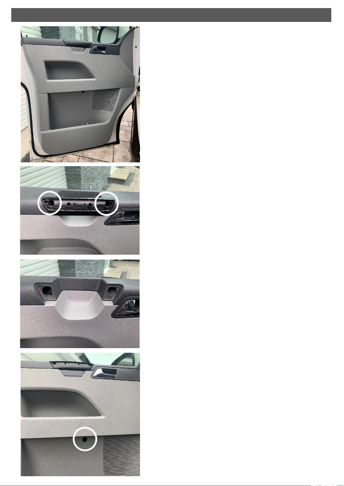
12.Connect the speaker wiring adaptor
and make a small hole in the rubber
grommet. Pass the speaker wires
through the grommet into the door
cavity. Ensure the wiring is kept tight
against to door skin as to not
obstruct the window when lowered
down
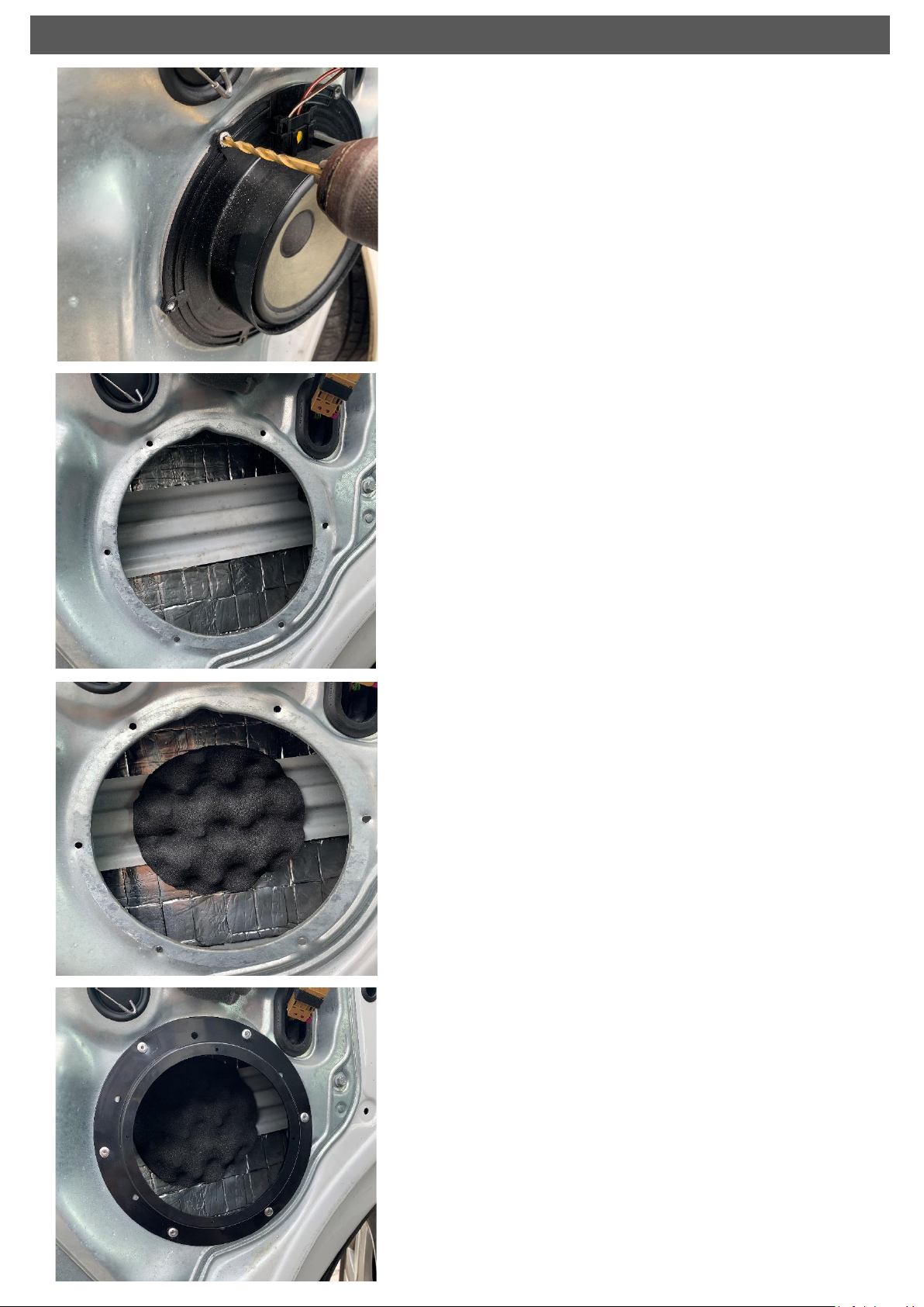
13.Insert the silicon baffle into the
speaker adaptor and line up the
securing holes. (6.5” version only)
14.Connect the speaker spade terminals
to the woofer ensuring the polarity is
correct (Red Positive +, Black
Negative -) Line up the holes and
silicone baffle and use the screws
provided to secure to the speaker
adaptor
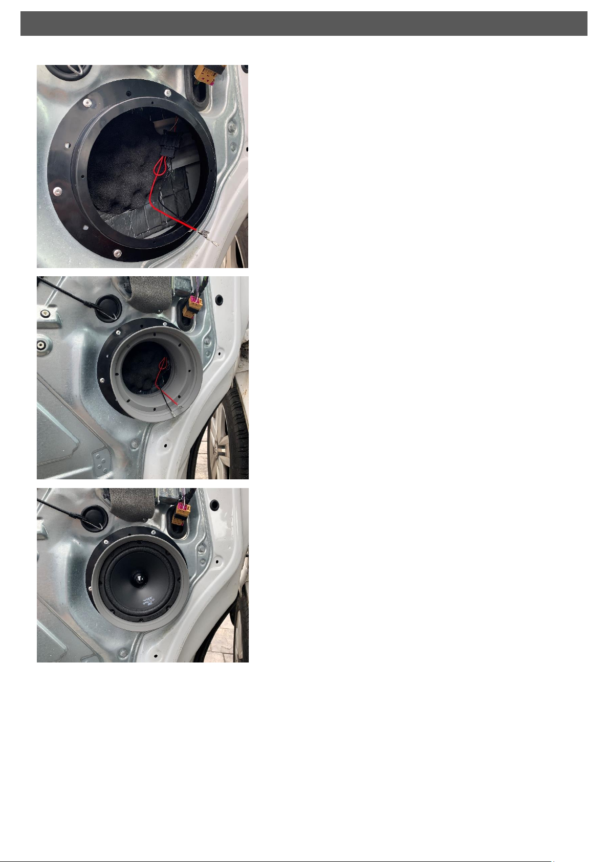
Test the speaker and re-install the
door card. Re-installation is a
reversal of the removal process.
NOTE Please check the window does
not catch the Speaker on the 8” kit
when full down. If it does please add
a 2 mm spacer or foam gasket to the
back of the speaker. Extra Sound
deadening included which can be
fitted under the adapter and
speaker if need (8” version only)
Replacing the Door Speaker continued…
15.To remove the factory tweeter (if fitted)
first use a trim removal tool to remove
the dash cover. Lift the front edge first
and remove completely
16.Remove the tweeter (if fitted) by
removing the two T15 Torx screws
securing the tweeter mount to the dash
and unplugging the tweeter connector.
Safely retain the mounting screws for
reinstallation
17.Before fitting the new tweeters, please
make sure the crossover or capacitor is
used to protect the tweeter. (See
Section 21 for details.)
Secure the OPTI1C tweeter to the new
tweeter mount using the metal locking
ring provided.
18.For vehicles that are not fitted with
factory tweeters in the dash, the OPTI1C
tweeter wires will need to be routed to
behind the stereo. Connect the T Crimp
connecters as shown to the Tweeter
wires and clamp closed using pliers or
similar.
Please make sure the included
crossover is used. This can vary from
the kit order from inline to separate
yellow cap. This should be used on the
positive cable
Replacing the Tweeter T5 kit Dash Board Placement (T6 Fitting See 15B)
Vehicles WITHOUT factory fitted Tweeters
19.Connect the T-Crimp connectors to the
stereo front speaker output wires. Take
special care to ensure the polarity is
correct so power correctly flows
through the tweeter crossover. If unsure
refer to your stereo user guide or wiring
diagram. (Tweeter wiring, Black/White –
Positive +, Black –Negative -)
Note: Failure to complete this step
correctly may result in damage to the
tweeter
20. Add the bullet connectors provided to
the tweeter connector provided taking
note of the polarity. Red connects to the
tweeter wire (black/white) and black
connect to the tweeter wire (black)
21. Cut back the tweeter wiring ensuring
the crossover/capacitor remains in-line
with the positive wire (Black/White).
Add the blue bullet connectors provided
and connect to the tweeter connector.
Ensure the Polarity is correct and
connected as below
Tweeter Tweeter Connector
Black/White to Red
Black to Black
Note: Failure to complete this step
correctly may result in damage to the
tweeter
22. Reconnect the tweeter in the vehicle
and secure the tweeter mount using the
T15 screw previously removed. Test for
correct operation and refit the dash
cover
Vehicles WITH factory fitted Tweeters
15B. To gain access the tweeter on the T6
the A pillar needs removing.
A trim tool is recommended to remove
these to avoid breaking anything.
16B. Once removed the Tweeter is now
able to be removed. These are plastic
welded into place from factory and can
easily be removed with the use of heat and
a small amount of pressure.
Please refit in reverse. A glue gun may be
needed at this point
17B. The tweeters are to be fitted into the
original place and plug into the original
position.
These can be soldered and wrapped or use the
supplied Bullet connectors.
See point 20 and 21 for full details.
Note: Failure to complete this step
correctly may result in damage to the
tweeter which is not covered by
warranty.
Replacing the Tweeter T6 A Pillar
T6 with factory fitted Tweeters
Tel: 0121 311 9090 Email: info@midbass.co.uk
Warranty
All VIBE products carry a full 12-month warranty, valid from the date of the original
receipt and proof of purchase (UK only). The original receipt and packaging should
be retained for the full 12-month period. If the product develops a problem at any
stage during the warranty period, it should be returned to the point of purchase,
complete and in its original packaging.
A full description of VIBE’s warranty information can be found on our website.
What is not covered
- Damage to a product due to improper installation
- Subsequent damage to other components
- Damage caused by exposure to moisture, excessive heat, chemical cleaners
and / or UV radiation
- Damage through negligence, misuse, accident, or abuse. Repeat returns for
the same fault may be considered abuse
- Any cost or expense related to the removal and / or re-installation of the
product
- Damage caused by amplifier clipping or distortion
- Items repaired or modified by any unauthorised repair facility
- Return shipping on non-defective items
- Products returned without a return’s authorisation number
- Damage to product by sealant use.
International Warranty
Contact your international VIBE dealer or distributor concerning specific procedure
for your country’s warranty policies. www.vibeaudio.co.uk
Additional Upgrade Options Available
Want to upgrade your sound further…Why not amplify your speakers or add a
subwoofer for a whole new listening experience. Please visit www.vibeaudio.co.uk
for more information.
Tel: 0121 311 9090 Email: info@midbass.co.uk
POWERBOX65.4M-V7
- Super compact 4 channel amplifier
- 4 X 65 Watts RMS
- Simple plug & play installation
- No need to install separate power and speaker wires
- Plug in-line with an original or aftermarket stereo
POWERBOX400.1M-V7
- Ultra-compact 400 RMS / 800W Peak mono amplifier
- Simple installation using the Rapid Fit wiring kit
(RAPAWK5M & RAPAWK2.5M)
- Can be used with the original or aftermarket stereo
- Perfectly matched to our compact subwoofer enclosures
OPTISOUNDAUTO8-V2
- Slimline 8” passive or active enclosure
- Ported enclosure technology
- Designed to fit the smallest of spaces
- Perfect for adding bass without compromising space
OPTISOUNDAUTO8A-V2
- Built in 300W RMS / 900W Peak Amplifier
- Amplifier wiring included
BLACKAIRT12S-V6
- Slimline 12” passive radiator subwoofer enclosure
- Ultra-slim profile
- Dual 4 Ohm voice coil configuration
- 300W RMS / 900W Peak
PULSEC8-V0
- Ultra-compact under seat enclosure
- compact and slimline design
- Cast aluminium housing
- 6x8 inch subwoofer
- 80W RMS / 240W Peak

This manual suits for next models

5

Other Vibe Car Speakers manuals

Vibe BlackAir 5 User manual

Vibe

Vibe BlackAir 5 User manual

Vibe BlackAir 5 User manual

Vibe

Vibe BlackAir 5 User manual

Vibe SEK10 User manual

Vibe

Vibe SEK10 User manual

Vibe PULSE6C-V4 User manual

Vibe

Vibe PULSE6C-V4 User manual

Vibe Slick 3C-V2 User manual

Vibe

Vibe Slick 3C-V2 User manual

Vibe qb69 User manual

Vibe

Vibe qb69 User manual

Vibe BlackDeath PRO-8M User manual

Vibe

Vibe BlackDeath PRO-8M User manual

Vibe blackDeath Series User manual

Vibe

Vibe blackDeath Series User manual

Vibe OPTISOUNDBMW8-V4 User manual

Vibe

Vibe OPTISOUNDBMW8-V4 User manual

Vibe BLACKAIR PRO 4.5T User manual

Vibe

Vibe BLACKAIR PRO 4.5T User manual

Vibe SLICK PRO 37T User manual

Vibe

Vibe SLICK PRO 37T User manual

Vibe SA-k Series User manual

Vibe

Vibe SA-k Series User manual

Vibe BLACKAIR6C-V0 User manual

Vibe

Vibe BLACKAIR6C-V0 User manual

Vibe BLACKDEATH PRO 3T User manual

Vibe

Vibe BLACKDEATH PRO 3T User manual

Vibe SLICK SQ Series User manual

Vibe

Vibe SLICK SQ Series User manual

Vibe 69 Coaxial PULSE69-V4 User manual

Vibe

Vibe 69 Coaxial PULSE69-V4 User manual

Vibe OPTISOUNDMERC4-V2 User manual

Vibe

Vibe OPTISOUNDMERC4-V2 User manual

Popular Car Speakers manuals by other brands

Premier TS-W3001D4 Specifications

Premier

Premier TS-W3001D4 Specifications

Blaupunkt GTt 1200 Mk II operating instructions

Blaupunkt

Blaupunkt GTt 1200 Mk II operating instructions

Blaupunkt VX 130.2 Notes on installation and operation

Blaupunkt

Blaupunkt VX 130.2 Notes on installation and operation

Rockville RockZR installation instructions

Rockville

Rockville RockZR installation instructions

Infinity kappa Series manual

Infinity

Infinity kappa Series manual

JBL Grand Touring GTO507C owner's manual

JBL

JBL Grand Touring GTO507C owner's manual

DLS BRUXUX56 manual

DLS

DLS BRUXUX56 manual

m-Dimension Element owner's manual

m-Dimension

m-Dimension Element owner's manual

Focal Access 130 A1 user manual

Focal

Focal Access 130 A1 user manual

Pioneer TS-G1641R instruction manual

Pioneer

Pioneer TS-G1641R instruction manual

EarthQuake Focus F4.0 Owner's manual & warranty

EarthQuake

EarthQuake Focus F4.0 Owner's manual & warranty

MAXTEK 69166 user guide

MAXTEK

MAXTEK 69166 user guide

Wharfedale Pro TITAN SUB-A15 quick guide

Wharfedale Pro

Wharfedale Pro TITAN SUB-A15 quick guide

JEHNERT SOUND DESIGN 68501 Assembly instruction

JEHNERT SOUND DESIGN

JEHNERT SOUND DESIGN 68501 Assembly instruction

Phoenix Gold R5CX user manual

Phoenix Gold

Phoenix Gold R5CX user manual

Sony CXS-GT2213 instructions

Sony

Sony CXS-GT2213 instructions

Infinity 505cs instructions

Infinity

Infinity 505cs instructions

Fostex FF225WK owner's manual

Fostex

Fostex FF225WK owner's manual

manuals.online logo
manuals.online logoBrands
  • About & Mission
  • Contact us
  • Privacy Policy
  • Terms and Conditions

Copyright 2025 Manuals.Online. All Rights Reserved.