ENSONIQ EPS-16 PLUS User manual

Keyboard and
Rack
PIN
93120013 01-A Isnscnial@
THE
TEcHNOLOGY
THAT
PERFoRMS

ENSONIQ Customer Service
Hours:
Monday through Friday
9:30
AM
to
6:30
PM Eastern
Time
Closed for lunch 12:15 PM
to
1:15PM
EPS-J6
PLUSService Manual
NOTES:
Parts ordering
in
U.S. and Canada:
1-800-441-1003
Table
of
Contents
TABLE
OF
CONTENTS
Page
Important
Things to Know About the EPS-16 PLUS:
1. Getting
Around
the
EPS-16
PLUS . . . . . . . . . . . . . . 1
2.
Keyboard
and
RackSimilarities
..
. . . . . . . . . . . . . . 1
3.
The
EPS-16
PLUS Keyboard Assembly and the Rack
KPC
Simulator 1
4. TheDisk Drive . . . . . . . . . . . . 2
5. Operating System (O.S.) . . . . . . . . 3
6.
Plastic Case
(EPS-16
PLUS
Keyboard only) 3
7.
EPS-16
PLUS
Rack
Screws
..
. 4
8. High Retention Force Connectors 4
Figure 1 -
Scribe.
. . . . 4
Communications
Path
. . . . . . 5
Figure
2 - Communications
Path
5
Power
Supply
Checking
the Power
Supply.
...
. . . . . 7
Figure
3 - AC Line Voltage CheckPoints . 7
AC
Line Voltage Measurements . . . . . . 7
Power
SupplyMeasurements . .
...
. . . . 8
Figure
4 -
Power
Supply Voltage CheckPoints 8
Transformerand
Power
Supply Voltage CheckPoints 8
Testing
the Power Supply Unloaded
..
. . . . . . . . 9
Figure
5 - Incorrect
Power
SupplyVoltages (flow chart) . 9
Display
Display
Self-test
Mode.
. .
Self-Test
Chart.
. .
.'
. .
Troubleshooting
Guide.
. . . . . . . .
Figure
6 - Footswitch
problem
(flow chart)
Figure 7 -
No
LEDs
Lit
(flow chart) . . .
Figure
8 -
Some
LEOs Lit (flow chart) . . .
Figure 9 -
All
LEDs Lit,
No
Display (flow chart)
Most
Commonly
Asked
User Questions
EPS-16
PLUS
Test
Procedure:
1.
Power
Up
........
.
2.
Load
in Sounds
............
.
3.
Keyboard
Test
(EPS-16
PLUS
Keyboard Only) .
4.
Disk
Check . . . . . • • . . . . . . . .
5. Sound
Check
. . . . . . . . . . . . .
6.
Mono Output
and
Headphone Test . . . . .
7.
MIDI Test
(EPS-16
PLUS Keyboard Only)
8. Footswitch
Test
. . . . . .
9. Analog
Test
Page . . . . . .
10. Sampling
Test
. . . . . . .
11.
Output
Expander
(OEX-6)
Test
12.
ESP
Effects Test 1
.....
13.
ESP
Effects
Test
2 . . . .
EPS-16
PLUS
Burn-in
Test
Program
EPS-J6
PLUSService Manual
10
10
11
12
13
14
15
16
17
17
17
17
18
18
18
18
19
19
19
20
20
21
Table
of
Contents-1
Tableo!
Contents
EPS-16
PLUS
Hardware
Notes:
EPS-16
PLUS
Keyboard
and
Rack . . . . . . . . .
Figure
10 -Trace
cut
for
Rev A, B,
or
C Main Boards
Keyboard
Only
. . . . . . . . . . . .
Rack Only
..............
.
Figure
11
-Hardware Notes for the Rack .
Error
Messages . . . . . . .
.'.
. . . . .
Software
Notes:
Checking
the Software Version
Bootup
ROM Changes . . . .
O.S.
Disk
Version 1.10 Changes
EPS-16
PLUS Keyboard Only Section
...
Figure
12
-EPS-16 PLUS Keyboard. ExplodedView
Section A - Replacing the
EPS-16
PLUS Main Board . . . .
Section B - Replacing the
EPS-16
PLUS Keypad/Display Board.
Figure 13 -
EPS-16
PLUS Button Colors . . . . . . . . .
Section C - Replacing the
EPS-16
PLUS Keyboard . . . . .
Figure
14
-Bottom
of
Case
.............
.
SectionD - Replacing the
EPS-16
PLUS
Power
SupplyBoard.
Section E - Replacing the
EPS-16
PLUS Transformer . . . . . .
SectionF - Replacing the
EPS-16
PLUS PitchIModWheel Assembly
SectionG - Replacing the
EPS-16
PLUS LineFilter .
Section H - Replacing the
EPS-16
PLUS Disk
Drive.
EPS-16
PLUS Rack Only Section
......
.
Figure
16
-
EPS-16
PLUS RackExplodedView
..
Section A - Replacing the
Rack
MainBoard . . . .
Section B Replacing the
Rack
Keypad/Display Board.
Section C - Replacing the Rack KPC Simulator Board.
SectionD - Replacing the
Rack
PowerSupplyBoard
Section E - Replacing the RackTransformer . . . .
SectionF - Replacing the
Rack
OEX-6 Board . . .
Section G - Replacing the
Rack
Line
Filter.
. . . .
SectionH - Replacing the RackDisk
Drive.
.
...
. .
Section J - Replacing the
Rack
MemoryExpanderBoard . .
Drawings
Figure 1 - Scribe . . . • . . . . . . . .
Figure 2 - Communications Path . . . . . . . . . . .
Figure
3-
AC
Line Voltage Check
Points.
. .
Figure 4 -
Power
Supply Voltage CheckPoints . . . .
Figure 5 - Incorrect
Power
Supply Voltages (flow chart) .
Figure 6 - Footswitch problem (flow chart) . . . .
Figure 7 -
No
LEOs
Lit
(flowchart) . . . . . . .
Figure 8 -
Some
LEDs
Lit
(flow chart) . . . . . .
Figure 9 -
All
LEDsLit,
No
Display (flow chart) . .
Figure
10 -
Trace
cut
for
Rev
A,
B,
or
C Main Boards
Figure
11 -Hardware Notes for the
Rack
only..
. . . . . . . .
Figure
12-
EPS-16
PLUS Keyboard Exploded View
Figure 13 -
EPS-16
PLUS
Button Colors . . . . . . . .
Figure
14
-Bottom
of
Case
...........
...
.
Hgure
16
-
EPS-16
PLUS
RackExplodedView
..
23
23
23
24
24
25
25
25
26
27
28
29
29
30
30
31
31
32
32
33
33
35
36
37
38
39
39
40
40
41
41
42
4
5
7
8
9
12
13
14
15
23
24
28
30
31
36
Table
of
Contents-2 EPS-16
PLUS
Service Manual

Important
IMPORTANT THINGS TO KNOW ABOUT
THE
EPS-16
PLUS
IF YOU OONT
READ
ANY
OTIIER PART OFTIllS MANUAL, READ TIllS SECTION.
As
with every
ENSONIQ
product, all EPS-16 PLUS service will be handled through
the
ENSONIQ
Module
Exchange
Program. Rather than diagnose
and
exchange individual components, you will
replace complete
mcxlules.
We feel that this
is
the
most
time and cost effective method
of
repair,
both for you
and
your
customers.
The
instructions in this manual
are
for both the EPS-16 PLUS Keyboard
and
Rack
unless otherwise noted. Where
the
instructions
say
to
check
the
keyboard
of
the
EPS-16
PLUS, substitute acheck of
the
KPC
simulator board
on
the EPS-16 PLUS Rack.
When troubleshooting
an
EPS-16
PLUS,
remove
any
optional modules that might
be
present. This
will
prevent a faulty option
from
complicating your troubleshooting.
I.
GETTING AROUND THE EPS-16 PLUS
You will
need:
a.
EPS-16
PLUS
Operating System (O.S.) Disk
b.
EPS-16
PLUS
Test Disk (including test sounds)
c.
Communications Test Board
d.
EPS-16
PLUS
Musician's
Manual
2.
KEYBOARD
AND
RACK SIMILARITIES
The Main Board
and
PowerSupply board are the
same
for
both
the
EPS-16
PLUS
Keyboard and
Rack. However, there are physical differences that willrequire
you
to
specify
which
unit
you
are
orderingparts
for.
The disk drive
is
the
same for both units. The KeypadlDisplay boards
are
different .
..
Insteadof:a Poly-Key Keyboard assembly (with KPC board), the Rack has a
KPC
simulator board.
The KPC simulator
board.
passes information between
the
KeypadIDisplay board
and
the
Main
Board (like
the
KPC
boarddoes for
the
Keyboard
unit).
In the rest
of
this manual, wheneveryou
see "Keyboard assembly," substitute
KPC
simulatorfor
the
Rack (except where otherwise noted).
The operating system is only
on
the EPS-16PLUS
O.S.
disk. This disk
is
the
same
for
both the
EPS-16
PLUS Keyboard and
Rack.
.
The EPS-16
PLUS
Rack has
the
OEX-6
Output Expander and
:ME-16
PLUS
memory expander
built-in. These two expanders
are
options for the Keyboard unit. FLASHBANK
(FB-l
andFB-2
Kits) and SCSI (SP-2 Kit) are options for both.
3.
THE
IEPS-16 PLUS KEYBOARD ASSEMBLY
and
the
KPC SIMULATOR BOARD
The
Poly-KeyTM
Pressure Keyboard assembly on the EPS-16
PLUS
(and the
KPC
siinulatorboard
on
the
RaCk)
is a complex
module
that contains its
own
computer and software.
So,
when
necessary, you
will
be swapping itout
as
a whole
unit
Display information sent
to
and
from
the
Main Board
is
processed
throQgh
the
Keyboard assemblylKPC simulator. What might appearto
be
afrozen display, therefore, could
be
abadKeyboard assemblylKPC simulator. For
more
troubleshooting hints, see Communications Path on
pp.
5-6 and
flow
charts on
pp.
9,
and
12-15.
EPS-J6 PLUS Service
Manual
pagel

Important
IMPORT
ANT! Keyboard assembly
EPROM
Version
(EPS-16
PLUS
Keyboard
only)
Each version
of
the
Keyboard assembly EPROM is optimizedfor the hardware that is within the
keyboard assembly. Formore information about the Poly-Key Keyboard assembly, see ENSONIQ
Service Bulletins
#9B
and
II.
The 2O-pin Ribbon Cable <Keyboard aSsembly/KPC Simulator)
When reconnecting this cable
to
the Main Board, make sure that the striped side is alignedwith
pin
1
and that the cable
is
not mis-pinned.
If
the cable
~
mis-pinned
or
installed backward, fuses F3
and
F4
on
the powersupply board will blow.
NOTE:
If
one fuse blows, the otherwill also blow; you
must replace both.
When installing
the
keyboard assembly back into the
EPS-16
PLUS, be sure that the keyboard
assembly cable
is
flat under the keyboard assembly andthatthe ferrite bead is not trapped on top
of
the main
board
.
4.
THE
DISK
DRIVE
Transportinl: a unit
There is a printedlabel near the DiskDrive
on
every new unit shipped. This label contains important
information concerning the care
of
the
EPS-16
PLUS DiskDrive and lists recommendations
regarding the treatment
of
the drive
during
transport.
We
do
not,
under
any
circumstances,
recommend
the
insertion
of
an
actual
disk
during
transport.
Transport the
unit
only with
nothing
in
the drive at
all.
PLEASE
DO
NOT
SHIP
AN
EPS-16
PLUS
OR
A
REPLACEMENT
DISK
DRIVE
IN
A
BOX
PACKED
WITH
PEANUTS.
If
you must, wrap the entire unit in plastic first.
These peanuts may cause severe damage
to
theDiskDrive
or
Keyboardassembly.
What disks to use
Itis veryimportantto use double-sided, double-density 3.5" micro-floppy disks.
The
EPS-16
PLUS writes information to every track
on
a disk, so
it
is imperative that the disk be
of
superior
quality
and
certified for double-sideduse.
Testini
the DiskDrive
The bestway to test the DiskDrive is
by
formatting a disk. When a disk is formatted, the
EPS-16
PLUS
reads
and writes every track
on
thatdisk.
If
the formatting attemptfails,
it
is likelythat
the
diskitselfis faulty. Always try formatting anotherblank disk before determining that theDiskDrive
is faulty. Unlike some computer systems,
the
EPS-16
PLUS does not automatically discard bad
sectors when formatting. The entire diskmust
be
goodfor successful formatting.
.
See Hardware Notes.-Rack Only for notes aboutthePanasonic DiskDrive.
page
2
EPS-J6
PLUS
Service
Manual
Important
5.
OPERATING SYSTEM (O.S.)
An
EPS-16
PLUS
O.S. takes up approximately 170 blocks on a disk
so
without the
O.S.
on
a disk
you have more room for sounds. The O.S. version on the disk can be easily updated (call
ENSONIQ Customer Service for the latest O.S. version). You cannot copy the O.S.
to
a disk onto
which you have already saved instruments or sequences, but not the O.S. Attempts to
do
so
will
result
in
an error message.
To
update O.S. Version on a floppy disk:
-Insert the disk containing the O.S. you want tocopy (the source disk) into the floppy
drive.
-Press Command, then System-MIDI, then 1 (Envl). The display shows COPY OS
TO
DISK.
-Press Enter-Yes. The display says MUST ERASE MEMORY, OK?
If
you need
to
save
any
sounds or sequences, press Cancel-No and save the data before proceeding.
-Press Enter-Yes. The display says READING
OS
INTO MEMORY, and then INSERT
FORMATTED DISK.
-Insert the disk onto which you want to copy the
O.S.
(the destination disk) into the floppy drive.
- .Press Enter-Yes. The display shows WRITING
OS
TO DISK while the
O.S.
is being copied
to the disk.
\Vhen it's done,
the
display reads COPY
OS
DONE. ANOlHER?
If
you want to copy the
same
O.S. to another floppy disk, insert another formatted disk and press Enter-Yes. You
can
repeat
this procedure
as
many times
as
you like.
-
When
you
are
done, press Cancel-No.
6.
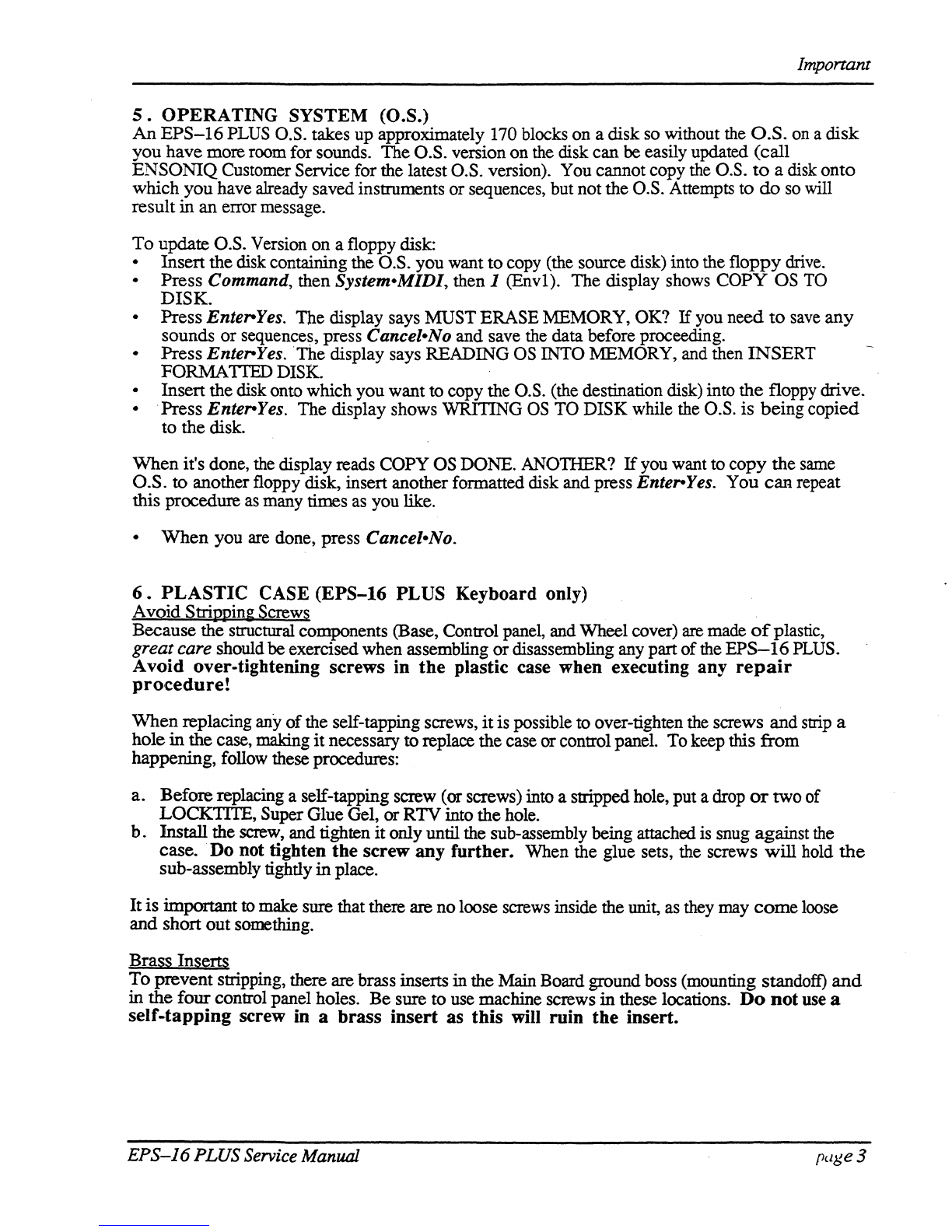
PLASTIC CASE (EPS-16 PLUS Keyboard only)
Avoid
Strippin~
Screws
Because the structural components (Base, Control panel, and Wheel cover)
are
made
of
plastic,
great care should beexercisedwhen assembling ordisassembling any part ofthe
EPS-16
PLUS.
Avoid over-tightening screws in
the
plastic case when executing any
repair
procedure!
\Vhen replacing
any
of
the self-tapping screws,
it
is possible to over-tighten the screws and
strip
a
holein the case, making
it
necessary toreplace the case
or
control panel. To keep this from
happening, follow these procedures:
a. Beforereplacing a self-tapping screw
(or
screws) into a stripped hole, put adrop
or
two of
LOCKTITE, Super Glue Gel,
or
RTV into the hole.
b.
Install the
screw,
and tighten itonly until the sub-assembly being attached
is
snug against
the
case. Do not tighten the screw any further. When the glue sets, the screws will hold
the
sub-assembly tightly
in
place.
Itis important
to
make sure that there are no loose screws inside the unit,
as
they may
come
loose
and short out something.
Brass Inserts
To
prevent stripping, there are brass inserts
in
the Main Board ground boss (mounting standoff)
and
in the four control panel holes. Be sure to use machine screws in these locations.
Do
not
use
a
self-tapping screw in a brass insert as this will ruin the insert.
EPS-16
PLUSService Manual page3

Important
7 .
EPS-16
PLUS
RACK SCREWS
Because
the
Control Panel is an aluminumextrusion, great care should
be
taken when assembling
or
disassembling
any
part
of
it
To
avoid stripping and
to
aid
in
alignment, you should
use
no
more
than 8 inchllbs
of
torque and try
to
install the screws into the existing holes in the panel.
8.
HIGH-RETENTION FORCE CONNECTORS (Repair Technicians Label)
In
all
EPS-16
PLUS
Racks and
in
later Keyboards, there
is
warning{mformation label
just
for
you.
We
just
wanted tolet you know that
we
have switched to a higherretention force connector
on
our
transformers.
This
means
it
will
be very difficult to remove this connector by
just
pulling.
We
recommend
the
use
of
a scribe, screwdriver
or
similarobject
to
remove this connector.
Due
to
the
benefits
of
a high-retention force connector,
we
will
be
adding them inotherplaces on the
EPS-16
PLUS
harness. Watch
out
for thein, andplease don't
pull
on
the wires!
We
have
found that some units have developed further problems once a module has been changed.
This
may
be
a result
of
improperhandling
of
cables.
We
suggestremoving allcable connectors
using the angledend
of
a scribe (see below).
- - ,
Figure
1-
Scribe
These
can
be found in the following catalogs:
• Techno-Toolcatalog 38, page 204, part number
400PRI44
•
Newark
catalog lID, page 1024, partnumber76-1510
page
4
,
EPS-J6
PLUSService Manual

Communications
Path
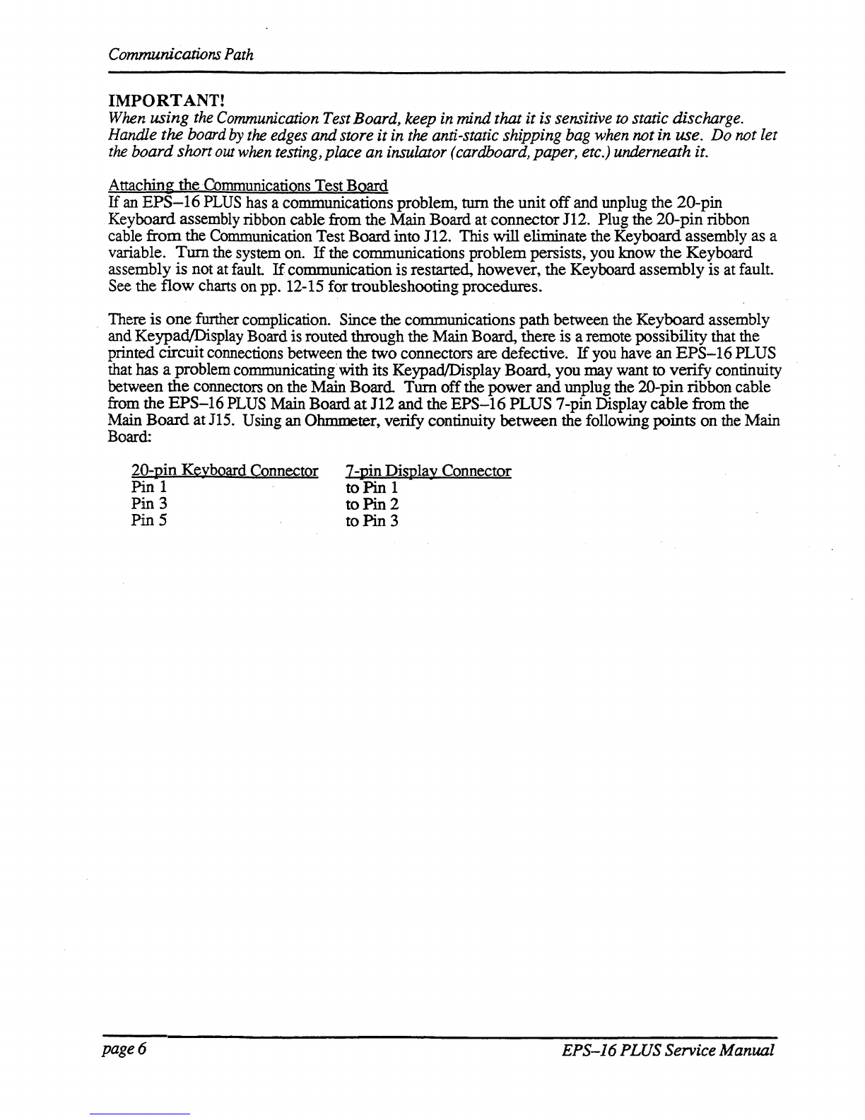
COMMUNICATIONS PATH
It
is
imponant
that you completely understand the communications
path
of
the
EPS-J6
PLUS.
Please readthis carefully.
The
EPS-16
PLUS
Main Board, KeypadlDisplay Board
and
Keyboard assembly are complete
computer
systems in themselves, each with its
own
microprocessor and operating software. The
modules communicate with each other using serial communication ports. Whenever a
key
is played
on
the Keyboard, for example, the Keyboard assembly microprocessortransmits this infonnation
to
the microprocessoron the Main Board.
The
KeypadlDisplay Boardcommunicates with the Main Boardthrough the Keyboard assembly.
Whenever
the Main Board wants to put a message on the Display,
it
sends the message
to
the
Keyboard
assembly which then passes
it
on
to the Display. Whenevera button is
pressed
on the
controlpanel, the KeypadlDisplay Board sends the message to the Keyboard assembly which, in
turn,
passes
it
on to the Main Board.
The
communications path
is
shown inFigure 2. The Main Board communicates with
the
Keyboard
assembly over a two-line asynchronous interface carried
by
the 20-pin Keyboard
assembly
ribbon
cable. 'The Keyboard assembly communicates with the Keypad/Display Board overa three-line
synchronous interface which is carried overto the MainBoard via the 20-pin ribbon
cable,
then
up
to
the Keypad/Display Board viathe 7-pin Display cable on the
EPS-16
PLUS and the
10-pinDispiay
cable
on
the
EPS-16
PLUS Rack.
Due
to
thecomplexity
of
the modules involved,
it
is often difficult
to
detemrlne which moduleis
at
fault when a communications problemoccurs.
To
facilitate troubleshooting, a Communication
Test
Board,
TestDisk and Bum-in Test Disk are available.
KEYPAD/DISPLAY BOARD
DATA DATA
CLOCK
IN
our
our
J
7-PIN
DISPLAY
CABLE
MAINBOARD
DATA
DATA
,0
()
0115
IN our C
4)
(~
112
2O-PIN
RIBBON
,,
CABLE
, , \
KEYBOARD!
DATA
DATA
DATA
DATA
CLOCK.
,
KPC
SIMULATOR our IN our
IN IN
ASYNCHRONOUS
SYNCHRONOUS
PORT
FORT
~\..
~
Figure
2 -Communications Path
If
a communication problem occurs (i.e.,
no
display orno response
to
button presses
or
keys),
it
could
be something as simple as a
ibad
ribbon cable
or
Display cable,
or
it
couldbe a
problem
in
one
?f
the
modules. To help you identify a faulty module, a special Communication Test
Board
is
mcluded
available from ENSONIQ Customer Service. The CommunicationTest
Board
simulates
the
operation
of
the
Keyboard assembly andcan be used
as
a "known good" module in
place
of
the
Keyboard
assembly fortroubleshooting.
EPS-J6
PLUS
Service Manual page5
Communications
Path
IMPORTANT!
When
using
the
Communication
Test
Board,
keep
in
mindthat it is sensitive
to
static discharge.
Handle
the
board
by
the
edges
andstore it
in
the
anti-static shipping
bag
when
notin use.
Do
not
let
the
board shan
out
when
testing,
place
an
insulator
(cardboard,
paper,
etc.)
underneath it.
Attaching the Communications Test
Board
If
an
EPS-16
PLUS has a communications problem,
turn
the unit
off
and unplug the 20-pin
Keyboard assembly ribbon cable from the MainBoard at-connector112. Plug the
20-pin
ribbon
cable
from
the Communication Test Boardinto 112. This will eliminate the Keyboard assembly as a
variable.
Turn
the system on.
If
the communications problempersists, you know
the
Keyboard
assembly
is
not at fault
If
communicationis restarted, however, the Keyboard assembly is at fault.
See the
flow
charts on pp. 12-15 for troubleshootingprocedures.
There is
one
funher complication. Since the communications
path
between the Keyboard assembly
and Keypad/Display Boardis routed through the Main Board, there is a remote possibility that the
printed circuitconnections between the two connectors
are
defective.
If
you have
an
EPS-16
PLUS
that has a problem communicating with its KeypadlDisplay Board, you may want to
verify
continuity
between
the
connectors onthe Main
Board
Turn
off
the
power
and
unplug the 2O-pin ribbon cable
from the
EPS-16
PLUS MainBoard
at
112
and
the
EPS-16
PLUS
7-pin Display
cable
from the
Main
Board
atJl5.
Using an Ohmmeter, verify continuity between the following points
on
the Main
Board:
20-pin Keyboard Connector
Pin 1
Pin
3
PinS
page 6
7-pinDisPlay Connector
to
Pin
1
to
Pin
2
to
Pin
3
EPS-J6PLUS Service Manual

EPS-J6PLUS
Power
Circuitry
CHECKING THE POWER SUPPLY
Many
EPS-16
PLUS problems may be related
to
a faulty PowerSupply, Transformer
or
Line Filter.
You
shouldcheck these before troubleshooting the rest
of
the unit.
Check
to
make sure that all the cable connections are secure and correct. Plug the
EPS-16
PLUS
in
and
turn
it
on.
Mter
the
EPS-16
PLUS has warmed up for five minutes, begin
to
test
the
voltages
at
the points shown in Figures 3
and
4~
If
the voltages vary outside the allowable limits, follow the
procedure described under TESTING
TIlE
POWER SUPPLY UNLOADED before replacing
it
Green
Line
Filter Top
Lug
@ WARNING!
There
are
dangerous
Voltages
present
in
this
area.
To
Power
",nT""'"
NOTE:
All
wires
come
from
the
bottom
of
the
transfonner.
Figure3
-
AC
Line Voltage
Check
Points
AC
LINE
VOLTAGE
MEASUREMENTS
(see Figure 3)
With the powerswitch OFF, With the power switch ON,
the proper
AC
Line Voltage
the
proper
AC
Line Voltage shouldread
from:
shouldread from: 2B-IA, 2B-IB, 2B-3B, 2B-3A
2B-IA, 2B-2A, 2B-3B There should be no voltage across the
power
switch.
EPS-J6
PLUSService Manual
page
7
EPS-J6
PLUS Power Circuitry
POWER
SUPPLY
MEASUREMENTS
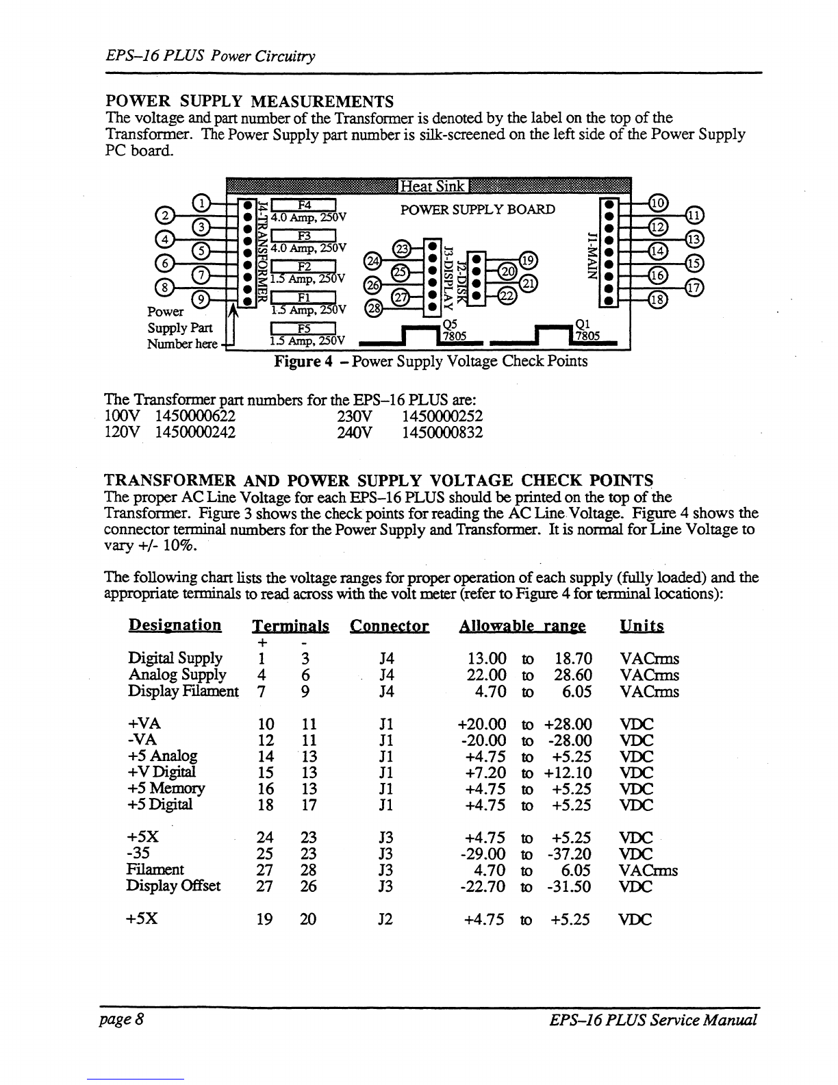
The voltage and part number
of
the Transfonner is denoted by the label on the top
of
the
Transformer.
The
Power Supply part numberis silk-screened on the left side
of
the Power Supply
PC board.
I F2 J
1.5
Amp,
25
v
I
FI
~
dAmp,25 V
F5
The Transformer part numbers forthe EPS-16 PLUS are:
100V 1450000622 230V 1450000252
120V 1450000242 240V 1450000832
TRANSFORMER
AND
POWER
SUPPLY
VOLTAGE
CHECK
POINTS
The proper AC Line Voltage for each EPS-16 PLUS should
be
printedon the top
of
the
Transformer. Figure 3 shows the checkpoints forreading the AC Line Voltage. Figure 4 shows the
connector terminal numbers forthe PowerSupply and Transformer. Itis normal for Line Voltage to
vary +/- 10%.
The following chart lists thevoltage ranges for properoperation
of
each supply (fully loaded) and the
appropriate terminals
to
read across with the volt meter (refer
to
Figure 4 for terminallocations):
De~i&nali2n
I~rmiDals
CQDD~s:tQ[
AIIQ!fa.bI~
[aD&~
Units
+
Digital Supply 1 3 J4 13.00 to 18.70 VACrms
Analog Supply 4 6 J4 22.00 to 28.60 VACnns
Display
Fllament
7 9 J4
4.70
to 6.05 VACrms
+VA 10
11
J1
+20.00 to +28.00
VDC
-VA 12
11
J1
-20.00 to -28.00
VDC
+5 Analog 14
13
J1
+4.75 to +5.25
VDC
+VDigital
15
13
11
+7.20
to
+12.10
VDC
+5 Memory 16
13
11
+4.75 to +5.25
VDC
+5Digital
18
17
11
+4.75 to +5.25
VDC
+5X
24 23
13
+4.75 to +5.25
VDC
-35 25 23 J3 -29.00 to -37.20
VDC
FIlament 27 28 J3
4.70
to 6.05 VACnns
DisplayOffset 27 26 J3 -22.70 to -31.50
VDC
+.5X 19 20 J2 +4.75 to +5.25
VDC
page8 EPS-J6PLUSService Manual

EPS-J6
PLUS
Power
Circuitry
TESTING
THE
POWER SUPPLY UNLOADED
If
the
Power
Supply
readings exceed the indicated tolerance (particularly the +5 Digital
line
between
tenninals 18 and
17
or
+5
Memory line between terminals 16and 13)
it
is possible that a defective
component
on
the
Main
Board
is drawing the Power Supply down.
In
this case, you
should
test
the
Power
SuppIy unloaded before proceeding.
Incorrect
power supply voltages
Tum
the
unit
OFF
Check the fuses.
Verify
the
the
properLine Voltage is
present
Turn the unit ON.
INCORRECT
POWER
SUPPLY VOLTAGES
===_---NO--
....
~~An
better nowJ
YES
Tum
the
unit OFF. Disconnect
the
Keyboard cable from the
main
board. Turn the unit ON.
...( Replace
the
Keyboard/KPC)
NO
---IPl~
Simulator (see Section C). .
YES
Turn
the
unit
OFF.
Disconnect the cable
between
the
powersupply and the
Keypad/Display Board.
Tmn
the unit
ON.
Replace
the
==----NO
~
Keypad/DisplayBoard
YES
Tmn the unit
OFF.
Disconnect the
cable
between
the
powersupply and
the main board.
Tmn
the unit ON.
(see Section B).
Replace the
Main
==---NO---1~
Board
(see
Section
A).
YES
Replace the Power Supply
Board (seeSection
D).
EPS-J6
PLUSService Manual
Figure 5 -
IncorrectPower
SupplyVoltages
page
9

Display Self-TestMode
DISPLAY
SELF·TEST
MODE
When
the KeypadlDisplay is receiving powerfrom the PowerSupply but is not in proper
communication with the Main Board, the K.eypad/Display Board enters Self·test
mode.
In Self-
test mode, theDisplay remains
blank:
until you press the buttons on the control panel. Pressing
various control panel buttons will cause the Display to printcharacters, home the cursor, etc.
Using
Self·test
Mode
to
Diagnose
the
Keypad/Display
Assembly
1.
If
the
unit
comes
in
with
a
blank
display,
but
is
in
Self·test
mode
(i.e., the Display
prints
out
characters when controlpanel buttons are pressedaccording to the chart below) this
indicates the problemis eitherthe Main Board
or
the communication linkbetween the Main
Board, Keyboard assembly and the KeypadlDisplay
Board
Beforereplacing anything, check all
connections, particularly the 20-pin cable to the Keyboard assembly.
If
pressingbuttons
ca~ses
only the leftmostcharacter
of
the display to change, this usually
indicates a defective cable connection (20-pin ribbon cable) between theMainBoardand
Keyboard
assembly orpossibly a badKeyboard assembly.
2.
If
the
unit
is
in
Self·test
mode
but
the
display
does
not
respond
according
to
the
chart
below, the problem is most likely in the KeypadlDisplay
Board
If
certain buttons
do
not
function properly during normal
EPS-16
PLUS operation, test them while the display is
in
Self-testmode.
If
you
can'tisolate a problemthat seems related to the display, the display can be forced into Self-test
mode using the follOwing procedure. With the poweroff, face the front
of
the unit, then:
Jumperthe left
(-)
side
of
C19 (located below the MIDI
Out
jack) topin 13
of
U20
(WD
1772).
On
power
up, the display will stay
in
Self-test as long as the
jumper
is connected, allowing you to check
the Keypad/Display Boardindependently.
The Chartbelow details how the controlpanel buttons are mapped in Self-testmode:
Eri:ss:
DiSula!
Bi:ads:
Pri:SS:
DiSula!
Ri:ads:
LOAD 8 Down Arrow
4.
COMMAND $ LeftArrow .
EDIT
1. RightArrow /
INS1RUMENT
CANCEL-NO ?
SEQ-SONG 3 EIDER-YES (Home Cursor)
SYSTEM:-M1DI 9 Instrument-Track 1 Space
EFFECTS
Instrument-Track2 &
l/ENV
1 + Instrument-Track 3 ,
2/Er:..c"'V2
0 Instrument-Track4 2
3/ENV3
1 Instrum.ent-Track 5 "
4/PITCH
6 Instrument-Track6 (Home Cursor)
5lFILTER 7 Instrument-Track7
5.
61AMP
< Instrument-Track 8 4
71LFO =
EFFEcr
SELEcr-BYPASS
2.
8/WAVE (Home Cursor) SAMPLE >
9/LAYER (Home Cursor)
RECORD
o.
O/I'RACK * STOP/CONTINUE 5
UpArrow
3.
PLAY
6.
pageJO
EPS-J6
PLUSService Manual
Troubleshooting Guide
TROUBLESHOOTING GUIDE
Often
the
faulty module
in
an
EPS-16
PLUS can be determined through normal use. Sometimes,
it
is
difficult toisolate the problem. The following flowcharts can help you diagnose
units
that appear
dead
(no
display).
When
troubleshooting an
EPS-16
PLUS, always disconnect any expansion devices
that
may be
present
(such
as
the memory expander, SCSIInterface or
OEX~
OutputExpander). This
will
prevent
a faulty expanderfrom complicating yourtroubleshooting. Theprocedures
for
testing the
Memory
Expander and the SCSIInterface are included with the corresponding expander. The
procedure
for testing the
OEX-6
can
be
found
on
p. 19.
The
following pages include troubleshooting flow charts:
~Problem
9 IncorrectPowerSupply Voltages
12 Footswitch problems
13
EPS-16
PLUS with
No
LEDs Lit
14
EPS-16
PLUS with Some LEDs Lit
15
EPS-16
PLUS with
All
LEDs Lit,
No
Display
Troubleshooting
an
EPS-16
PLUS with a Footswitch Problem (see
Figure
6)
If
one
or
both ofthe footswitches do not operate properly, make sure that the footswitches
are
set
to
the
proper
mode (on the Edit/System·MIDI page). See Section 2
of
the
EPS-16
PLUS
Musician's
Manual) formore information. .
The
SUSTAIN
Fr
SWITCHparameter corresponds to the right pedal
of
SW-5
or
single
pedal
SW-l.
The
AUX
FT
SWITCH parametercorresponds to the leftpedal
of
SW-5
only.
The
SW-5
is
the
Dual
Footswitch (piano-type) available fromENSONIQ. .
On
the Edit/S MIDIsystem· .page:
SUSTAIN
FT
SWITCH
AUX
FT
SWITCH
Footswitch
SW
-1 single footswitch,
or
SW
-5 left pedal
. SW-5 rightpedal
Default SUSTAIN OFF
Option rightPATCH SLbutton sequencerSTART/STOP
Option -leftPATCH SELbutton
If
the
footswitch modeis correct and thefootswitch still doesn't function properly,
there
is either a
problem
with the
Main
Board, the
KeyboardIKPC
or
the 2O-pinribbon cable
connecting
the two.
Although the footswitch
jack
is
mountedon the
Main
Board, the footswitch signals are carried
over
to.
the
KeyboardIKPC by the 2()-pinribbon cable, where they are sensedby the KeyboardIKPC
mlcroprocessor.
EPS-16PLUS Service Manual page
11
Troubleshooting Guide
TROUBLESHOOTING
AN
EPS-16
PLUS
WITH
A FOOTSWITCH
PROBLEM
~-NO
YES
Set both footswitches to act
as
Patch Select Buttons.
Press Edit then System-MIDI, scroll to
SUSTAINFI'SWITCH (right orsingle pedal) and
press the
up
arrow
button to set it
to
PATCH SL.
Scroll right
once
to
AUX
Fr
SWITCH (left pedal)
and
set it
to
PATCH SEL.
Select
PIANO
241. Press Edit, then double-click
on
Instrument. Pressing either footswitch should
cause
the
appropriate
patch
indicator
to
change in the
·Iefunost two characters
of
the display.
~----YES---""
NO
Turn the unit OFF. Attach the communications
testboard.
Tum
the unit ON and
boot
it
up
nonnally. The display will
show'"
KBD
FAll...ED-TRY
AGAIN?
Press Cancel·No.
page12
Load
in and then selectPIANO 241.
Set
both
footswitch to act
as
Patch
SelectButtons (see above).
~--NO
YES
Replace Keyboard/KPC
Simulator'
Board(see Section C).
...
If
your
communications
test
board
has
an
edge
connector
(4090013601)
this
message will
not
appear.
Replace the MainBoard
(see Section
A).
Figure 6 -
Footswitch Problem
EPS-16
PLUS
Service Manual

NoLEDs
lit.
YES
NO
i
Test
the
powersupply
: unloaded. Go
to
Incmrect
PowerSupply Voltages .
flow chan, p. 9.
E~S-16
PLUS
S~ice
Manual
YES
NO
Troubleshooting Guide
TROUBLESHOOTING
AN
EPS-16 PLUS WITH
NO
LEDS LIT
NO
Replace the
YES
Check
KeyboardIKPC
20-pin
ribbon
cable
for
improper
connnection
..
YES· KeypadlDisplay
Board (Section
B).
Figure 7 -
NoLEDsLit
page
13
Troubleshooting
Guide
TROUBLESHOOTING
AN
EPS-16
PLUS
WITH
SOME
LEDS
LIT
>--NO
Test the
power
supply
unloaded.
Go
to
Incorrect
Power
Supply Voltages
flow chart
on
p. 9.
YES
>-
__
NO_
........
Repaircable
JIll""
andretest.
YES
Place
scope ground onthe left
lead
(negative)
of
C19
and
probe
on
pin 4
of
J15-DISPLAY.
page
14
YES
Replace
the
KeypadlDisplay board
(see
Section
B).
>--NO
Replace the MainBoard
(see Section A).
Figure 8 -
SomeLEDs Lit
EPS-16 PLUS Service
ManZllll

ALL
LEDS
LIT,
NO
DISPLAY
Troubleshooting
Guide
TROUBLESHOOTING
AN
EPS-16
PLUS
WITH
ALL LEDS LIT,
NO
DISPLAY
Test the power supply
NO
...
unloaded.
Go
to Incorrect
:>---
--Ir.c
Power Supply Voltages
YES
Force
the
unit
into self-test mode:
Jumperthe negative (left) side
of
C19
to
pin
13
ofU20.
flow chan, p.
9.
...
Replace
the
~--
NO
--Ir-
KeypadlDisplay Board
(see Section B).
YES
>-
__
NO
___
Replace
the
Main
YES
YES
Replace
the
Keyboard/KPC
Simulatorboard (see Section C).
EPS-16
PLUS Service Manual
Board (see Section A).
">---NO
.c
Repair andretest. )
Figure 9 -
All LEDs Lit,
No
Display
page
15

User Questions
MOST
COMMONLY
ASKED
USER
QUESTIONS
The following questions are the most commonly asked
by
end
users. Our CustomerService
Representatives (CSRs) resolve these situations
over
the telephone daily.
Question:
CSR:
Question:
CSR:
Question:
CSR:
Question:
CSR:
pageJ6
How doI Mix a Track
or
a Song?
Sequences (Tracks)
1)
SetRECORD
MODE
to ADD (see Section 8 o/theMusician's Manual)
2) Select the Instrument-Track
3) Press Edit then Track, scroll left
to
MIX
4) Set mixto the desired value
5)
Hold
Record
and
press Play
6)
Letthe Sequencer play one bar
7) Press
Stop
8) Answer YES
to
KEEP=OLD -
NEW
In
Song Mode
1) Chain sequences into a Song
2)
SetRECORD
MODE
to
ADD
3) Select the Instrument-Track
4) Press Edit then Track, scroll left
to
MIX
5)
Hold
Record
and
press Play
6)
Mix Track through entire Song using the
Data
Entry Slider
or
the
CV
Pedal
withPED=VOL
7) Answer YES
to
KEEP=OLD -
NEW
The
EPS-16
PLUS will
not
record a sequence from external sequencer
in
MUL
11
mode.
You must have O.S. version 1.1
or
higher.
Why won'tthe
EPS-16
PLUS
let
me
edit
convertedMirage sounds?
WS=1 contains the actual wavesample informationfor the
Lower
sound, WS=17
for the Upper.
All
otherwavesamples
(30
of
them) are copies
of
WS=1
or
WS=17. Therefore. isolatethe desired wavesample(s) as follows:
1)
Create
a new Instrument (see Section 3
o/the
MusiCian's
Manu.al)
2) Create a
new
Layer
in
that Instrument(see Section 7
o/the
Musician's
Manuol)
3) Copy desiredwavesample into the
new
Layer
(see
Section
6o/the
Musician's Manual) .
4) Truncate the new wavesample (see Section 6
o/the
Musician's Manual)
5)
Edit as you wish
Why
do
someothermanufacturer's instruments crash when playedfrom an
EPS-16
PLUS keyboard?
Theseinstruments cannothandle the vast amount
of
MIDI
data
thatPoly-Key
generates. Turnthe
key
pressure settings
to
CHANor OFF
on
MIDI and each
INSTRUMENT, as follows:
1) Press Edit, then
System-MIDI
(see Section 2
o/the
Musician's Manual)
2)
Scroll to BASECHANNELPRESSURE=KEY
3)
Change
it to
CHANNEL
or
OFF
4)
Press
Edit, then
Instrument
(see Section 3
o/the
Musician's Manual)
5)
Scroll toPRESSURE MODE=KEY
6)
Change
it to
CHANNEL
or
OFF
EPS-J6PLUSService Manual
Other manuals for EPS-16 PLUS
2
Table of contents
Other ENSONIQ Musical Instrument manuals


