manuals.online logo
Brands
  1. Home
  2. •
  3. Brands
  4. •
  5. enware
  6. •
  7. Chiller
  8. •
  9. enware DFSA120 Installation and operating instructions

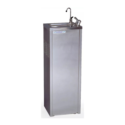
enware DFSA120 Installation and operating instructions

DFSA120
FREE STANDING BUBBLER
AND CARAFE FILLER - POWDER COATED
DFSA121
FREE STANDING BUBBLER
AND CARAFE FILLER - STAINLESS
Installation & Maintenance Instructions
FREESTANDING
WATER CHILLER
I00026_Sep20
Call 1300 369 273
www.enware.com.au
Enware Australia Pty Limited
9 Endeavour Rd Caringbah NSW 2229 Australia
Ph: 02 8536 4000 info@enware.com.au
2 Call 1300 369 273 www.enware.com.au
935
3
2
0
320
805 -810 MAX
160
75
160
½” WATER
INLET
40mm DRAIN
CONNECTION
BA
CK FACE OF WATER CHILLER
INSTALLATION COMPLIANCE
IMPORTANT - This must be read before proceeding with
installaon
1 Plumbing must be in accordance with AS/NZS3500 and
Plumbing Code of Australia (PCA)
 
AS/NZS3000-2007
 


* Note: Non Return Isolang Valves/Stop Taps are not
supplied with this product.
 


against pressure surges that may occur in the supply lines,


WARNING:
• 

• Stainless steel panel (non-powder coated) chillers are
not designed or recommended for use in corrosive

• 



• Do not operate this appliance at ambient temperatures
below 0°C, as it may cause the water inside the water

• 

• 
(including children) with reduced physical, sensory

knowledge, unless they have been given supervision


supervised to ensure that they do not play with the

Before proceeding with installaon, ensure all operang and dimensional specicaons are suitable for the
intended installaon.


TECHNICAL DATA
Technical Information
Chilled Water Production up to 18 Litres/hour
Recommended Water
Supply Pressure 50-500 kPa
Power Supply 240V / 50 Hz
Power Connection 3 pin 10 A plug with 2m lead
IP Rating IP23
Water Inlet Connection 1/2” BSP male
Water Drain Connection 40mm DWV PVC
Storage Tank 4 Litres
Compressor Size 362 W
Condensor Wire tube
Refrigerant R134A
Climate Condition SN.N *
Net Weight 28kg
Integral Pressure Limiting
Valve Rating 415 kPa
* Suitable for use in ambient temperatures of 10°C to 32°C
Enware products are to be installed in accordance with the Plumbing Code of Australia
and AS/NZS3500. Enware Australia advises: 1. Due to ongoing Research and
Development, specifications may change without notice. 2. Component specifications
may change on some export models. 3. Refer to Warranty Statement for warranty
details - www.enware.com.au/warranty
* Suitable for use in ambient temperatures of 10°C to 32°C
Enware products are to be installed in accordance with the Plumbing Code
of Australia and AS/NZS3500. Enware Australia advises: 1. Due to ongoing
Research and Development, specicaons may change without noce. 2.
Component specicaons may change on some export models. 3. Refer to
Warranty Statement for warranty details - www.enware.com.au/warranty
www.enware.com.au Call 1300 369 273 3
INSTALLATION INSTRUCTIONS
 

Note: This appliance must be placed in a horizontal posion. Ensure at least a
50mm gap is le between the back of the unit and any wall for fan venlaon.
 
IMAGE 1
IMPORTANT - CHILLER MUST BE DISCONNECTED FROM POWER SUPPLY BEFORE
ACCESSING THE INSIDE OF THE CHILLER UNIT (Read CAUTION note on next page).
 

IMAGE 2
 DFS002F


 


 
 

spit from the outlets during this procedure and care should be taken not to let



 

 


 


 

FRONT
PANEL
FIXING
SCREWS
IMAGE 1
CONNECT
TO 40MM
WASTE
BOTTLE
TRAP
WATER
INLET
IMAGE 2
CARAFE FILLER ASSEMBLY INSTRUCTIONS
 IMAGE 3
 
IMAGE 4
 
 
IMAGE 5
 
SLIDE HANDLE ON
FROM THIS SIDE
ADJUSTMENT NUT
POSITIONED
CROSS-WISE
IMAGE 3
IMAGE 5
 






 

IMAGE 4
MAINTENANCE
TROUBLESHOOTING
CAUTION
REFRIGERATION SYSTEM

Note: tampering with the refrigeraon system in any way may void warranty.
WATER TEMPERATURE CONTROL SCREW - Located internally on the shelf, has
C to 10

BUBBLER STREAM ADJUSTMENT





            



Every 6 months or periodically as required, the appliance and its
surronding area should be inspected for water leaks, the bubblers

          
         

Every 12 months or as required, the bubbler stream height should



should be checked periodically and cleaned with a brush or vacuum


CLEANING
          

agents containing a corrosive acid, scouring agent or solvent

coated surfaces should only be cleaned with a cloth and clear water





• Mains Power Electrical Components.    
safety and hygiene, access to the internal components of
this appliance is restricted to persons having knowledge and

• 

• If the power supply cord is damaged, it must be replaced by


• 
thermal cutout, this appliance must not be supplied through


• 
       

• 

• Do not use mechanical devices or other means to accelerate


•         
ambient temperatures is again above 0°C and frozen unit

COMPONENTS
PROBLEM CAUSE RECTIFICATION
No water at outlets  Connect and turn on water supply
Water frozen 


Water not cooled Power is not connected 
 
 

outlets
Bubbler stream is not adjusted Adjust bubbler stream
 
 
Water leaks at
outlets
Bubbler cartridge is damaged 
 
Water tastes foul  
Water in tank is stale Purge water in tank by running the bubbler for 5 minutes
HEX COVER NUT
PUSH BUTTON
CARTRIDGE
LOCKING RING
(RETAINING NUT)
CARTRIDGE
(BUB294)
SPOUT ASSEMBLY
BODY
FLOW
ADJUSTMENT
SCREW
IMAGE 6

This manual suits for next models

1

Other enware Chiller manuals
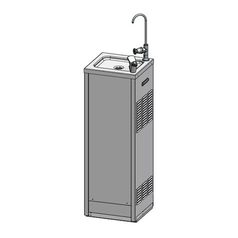
enware DFSA121-PBBF User manual

enware

enware DFSA121-PBBF User manual

enware DFSA121-CBF User manual

enware

enware DFSA121-CBF User manual

Popular Chiller manuals by other brands

EAS Electric ECH030NHR Owners & installation manual

EAS Electric

EAS Electric ECH030NHR Owners & installation manual

Huawei NetCol5000 C030H6B20 10020E1 quick guide

Huawei

Huawei NetCol5000 C030H6B20 10020E1 quick guide

Electrolux 726620 Brochure & specs

Electrolux

Electrolux 726620 Brochure & specs

iCool Compact Series owner's manual

iCool

iCool Compact Series owner's manual

Nordcap SKF 5 GN 1 manual

Nordcap

Nordcap SKF 5 GN 1 manual

Carrier 30HR Series Wiring diagrams

Carrier

Carrier 30HR Series Wiring diagrams

MAXA i-32V5C MIDI 0121 manual

MAXA

MAXA i-32V5C MIDI 0121 manual

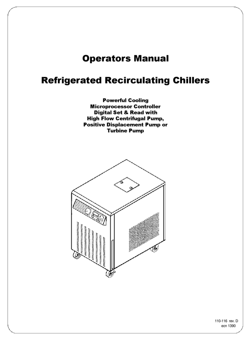
HP Refrigerated Recirculating Chillers Operator's manual

HP

HP Refrigerated Recirculating Chillers Operator's manual

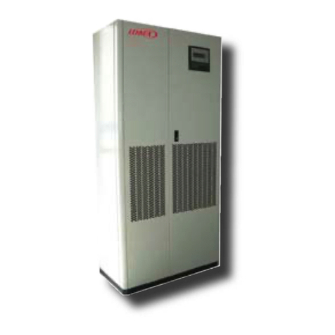
Lennox INNOVA DHADC Series Application guide

Lennox

Lennox INNOVA DHADC Series Application guide

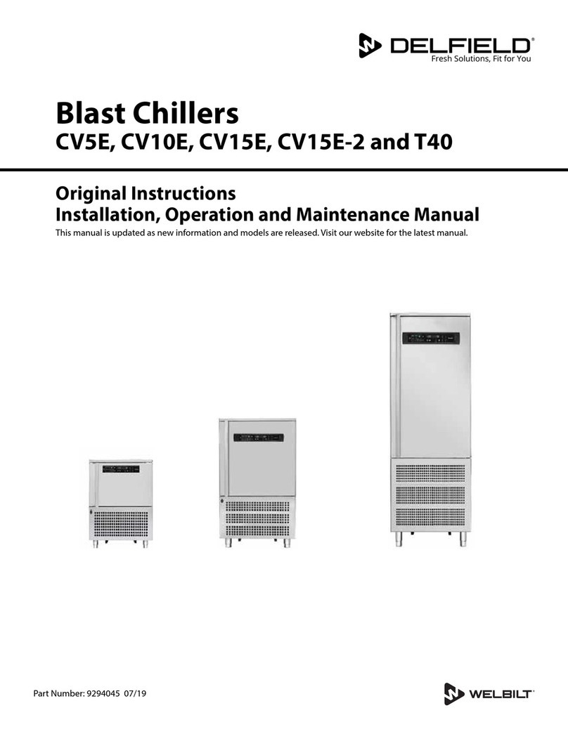
Welbilt Delfield CV5E Original instructions

Welbilt

Welbilt Delfield CV5E Original instructions

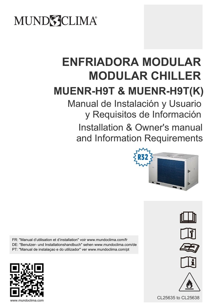
mundoclima MUENR-H9T Installation & owner's manual

mundoclima

mundoclima MUENR-H9T Installation & owner's manual

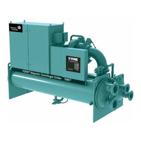
York YMC2 manual

York

York YMC2 manual

Skope SK1000 Operating and service manual

Skope

Skope SK1000 Operating and service manual

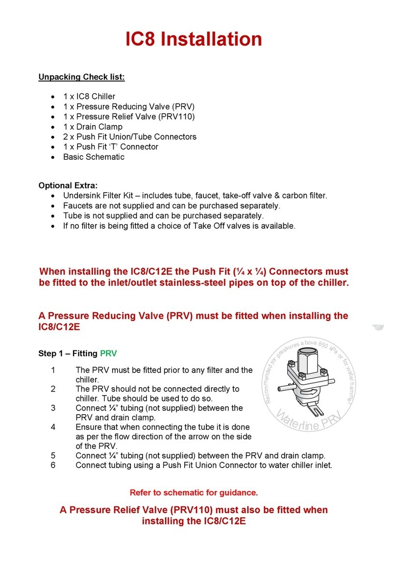
Waterworks IC8 Installation

Waterworks

Waterworks IC8 Installation

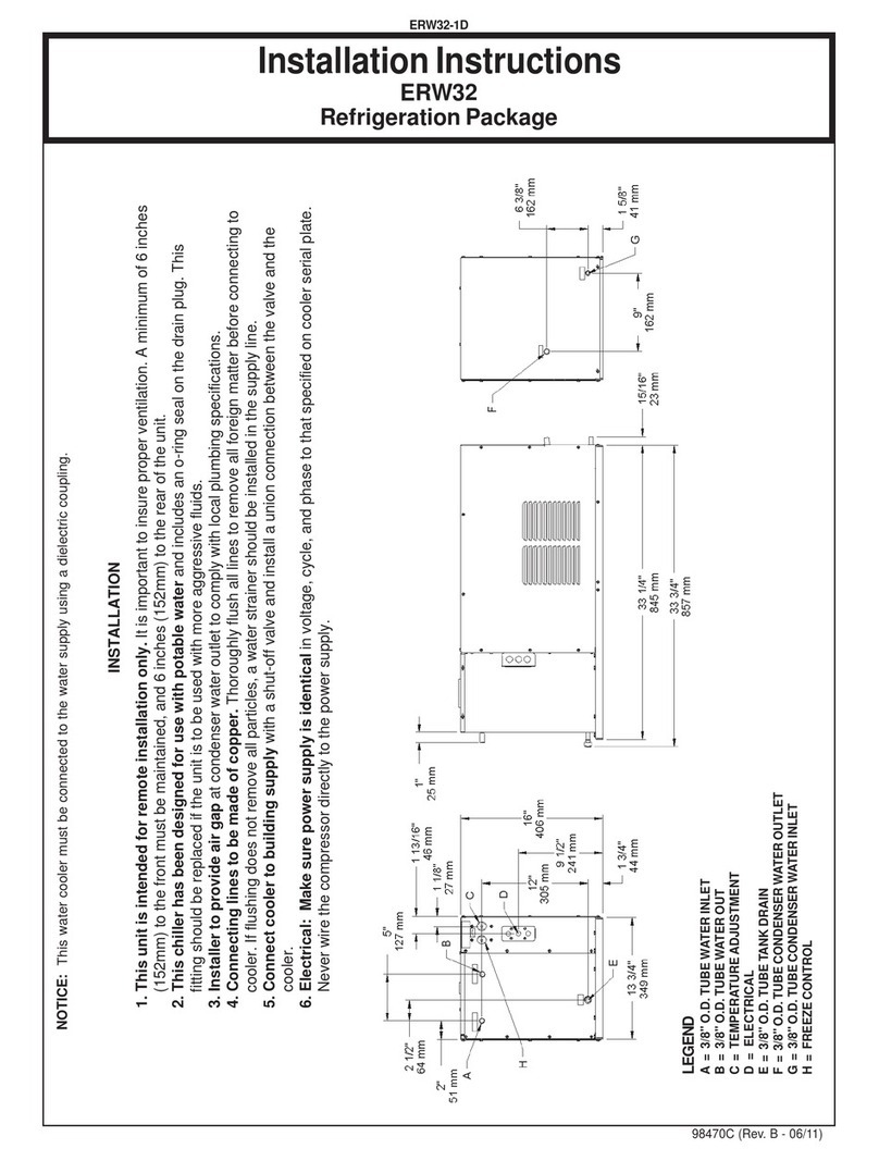
Elkay ERW32 installation instructions

Elkay

Elkay ERW32 installation instructions

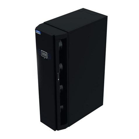
AIREDALE LogiCool InRak Technical manual

AIREDALE

AIREDALE LogiCool InRak Technical manual

Daikin Exigo E1500 Operation manual

Daikin

Daikin Exigo E1500 Operation manual

Emerson Liebert DM Chilled Water Series user manual

Emerson

Emerson Liebert DM Chilled Water Series user manual

manuals.online logo
manuals.online logoBrands
  • About & Mission
  • Contact us
  • Privacy Policy
  • Terms and Conditions

Copyright 2025 Manuals.Online. All Rights Reserved.