Enwork Equilibrium User manual

Equilibrium
Revision B 11/07/16
Conference Table
Installation Instruction


12900 Christopher Drive Lowell, MI 49331
800.815.7251 www.enwork.com
Specifications subject to change without notice. 3
Equilibrium End User Agreement
Enwork Equilibrium table bases must be installed directly onto a four inch
minimum thickness concrete floor using factory provided hardware.
Warning and Indemnity Agreement
Failure to install on four inch thick concrete floor or failure to follow installation
instructions may cause table to function improperly and could lead to personal
injury and or structural damage. Do not, under any circumstance, install on a
concrete floor less than four inches thick.
Equilibrium assembled can weigh up to 1,700 pounds supported in a three and a
half square foot area. It is the responsibility of the dealer to verify that the
location for Equilibrium is suitable and is properly installed. End user agrees that
the installation shall not be modified and the location of the table base shall not
be moved without assistance from an Enwork Dealer.
It is the responsibility of the dealer and end user to adhere to and follow any
local or state building, electrical and accessibility codes.
Enwork is not responsible for any structural failures or personal injuries or
property damage due to improper installation or improper use of product. End
user agrees to defend, indemnify and hold harmless Enwork from any claims of
any nature or type arising out of unauthorized modification or movement of the
table base or any other improper use of the product.
Note: Installation requires at least two people.

1) Tools and Supplies Required
INSTALLATION INSTRUCTION
4
Tape Measure Drill / Hammer Drill ½” Diameter
Masonry Drill Bit
Adjustable Wrench Socket Wrench
5/8” Socket
3/4” Socket
Level Phillips Drive
Utility Knife Marker Roll of Tape Vacuum
Hammer or Mallet
2) Parts and Fasteners Included
INSTALLATION INSTRUCTION
5
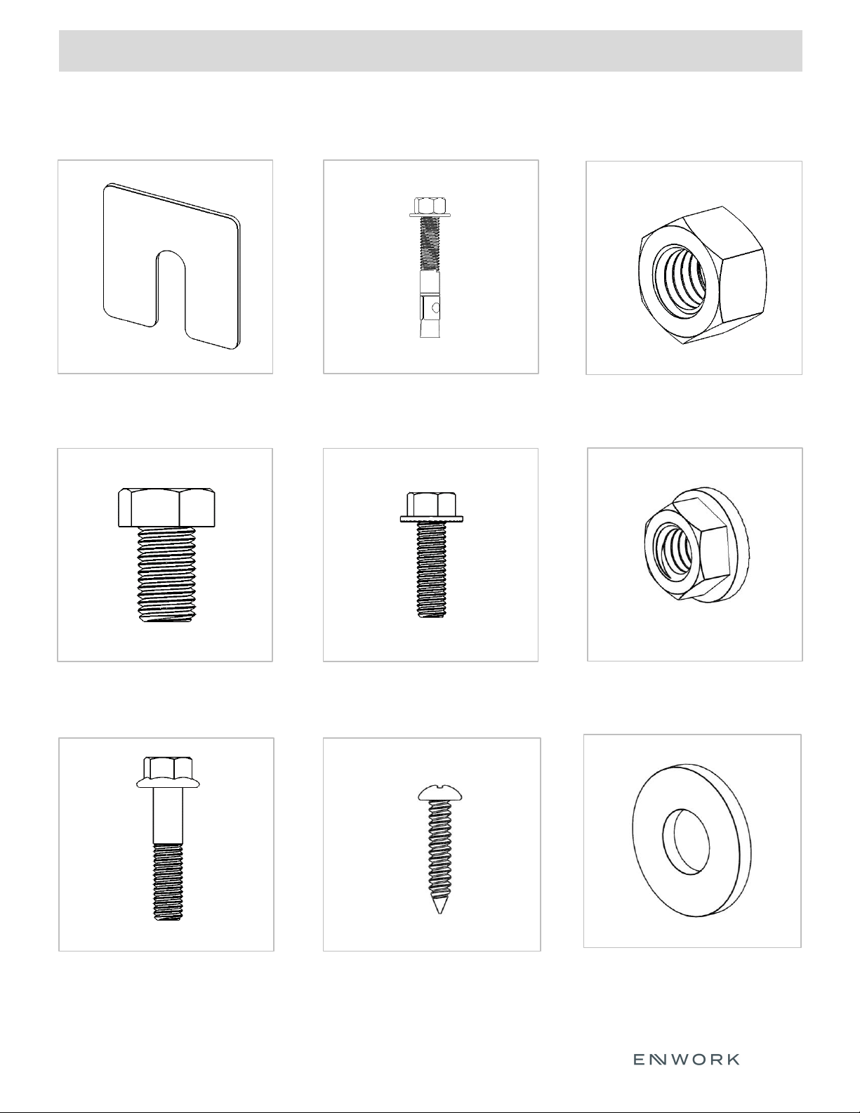
Aluminum Shim (Pack) ½” x 3 ¾” Concrete Stud ½” – 13 Hex Nut
¾” – 10 x 1 ¼” Hex Bolt 3/8” – 16 x 1 1/2” Flange Hex
Bolt
3/8” – 16 Flange Hex Nut
3/8”-16 x 2” Flange Hex Bolt #10 x 1 ¼” Pan Head Phillips 3/8” x 1” Flat Washer
2) Parts and Fasteners Included
INSTALLATION INSTRUCTION
6
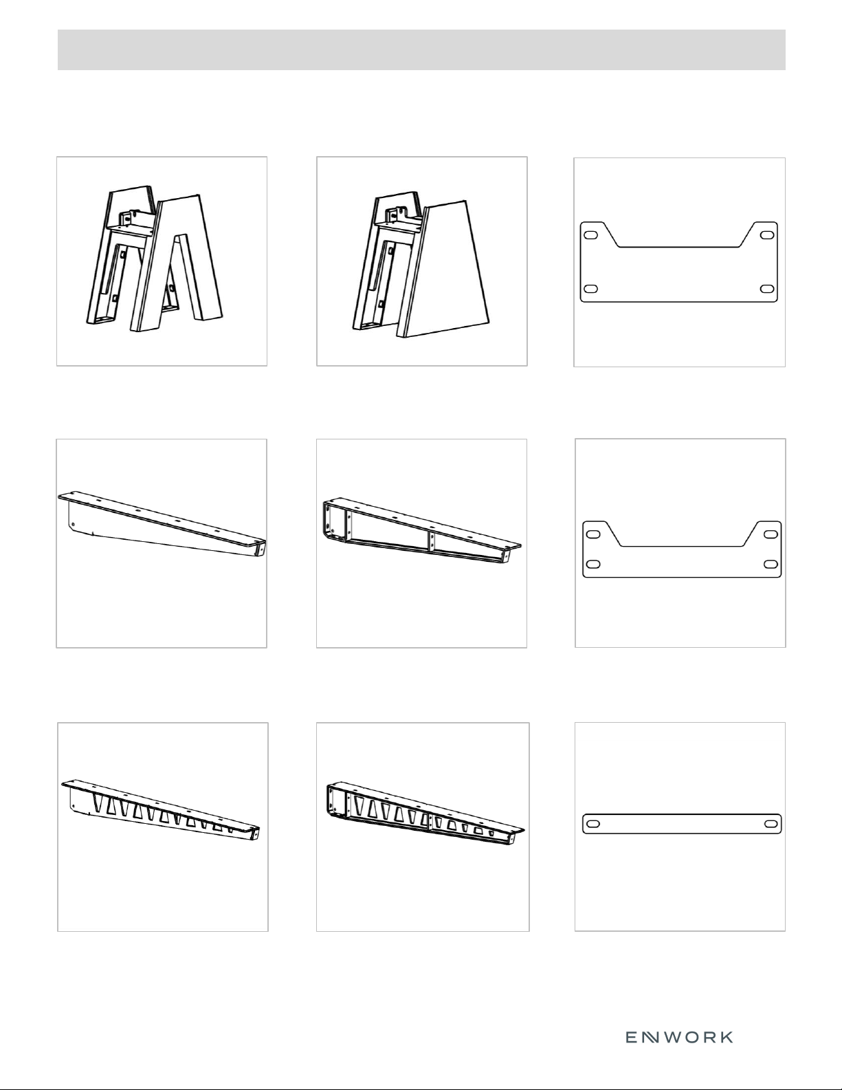
Right Side Top Support w/ Truss Design
EQM-2130-xx-R
or
EQM-2131-xx-R
End Tie Plate
EQM-1227
Left Side Top Support
EQM-2122-xx-L
or
EQM-2123-xx-L
Right Side Top Support
EQM-2122-xx-R
or
EQM-2123-xx-R
Mid Tie Plate
EQM-1228-1
or
EQM-1228-2
Inverted V Base
EQV296 / EQV298
EQV426 / EQV428
Triangle Base
EQT296 / EQT298
EQT426 / EQT428
Center Tie Plate
EQM-1229-1
or
EQM-1229-2
Left Side Top Support w/ Truss Design
EQM-2130-xx-L
or
EQM-2131-xx-L

2) Parts and Fasteners Included
INSTALLATION INSTRUCTION
7
Trough Cover End Cap
EQM-1247-xx
OR
EQM-1267-xx
Trough Cover
EQM-1248-xx
Left Hand Inner Leg Cover
EQM-2126-(1,2,3,4)-LH
all EQV style bases and EQTxxxI bases
Right Hand Inner Leg Cover
EQM-2126-(1,2,3,4)-RH
All EQV style bases and EQTxxxI bases
Base End Cover
EQM-1264-(1,2,3,4)
EQTxxxE bases
Center Spacer
EQM-1230
(OPTIONAL)
Oasis Mini Extension Kit
EQH-5007
Includes Qty 8, 3/8”-16 x 2 ¼”
Flange Bolts
For use with Oasis Mini
Mounted over bases
EQV296 / EQV426
EQT296 / EQT426

3) Assembly:
INSTALLATION INSTRUCTION
8
3
Installing the Base
3) Assembly:
INSTALLATION INSTRUCTION
9
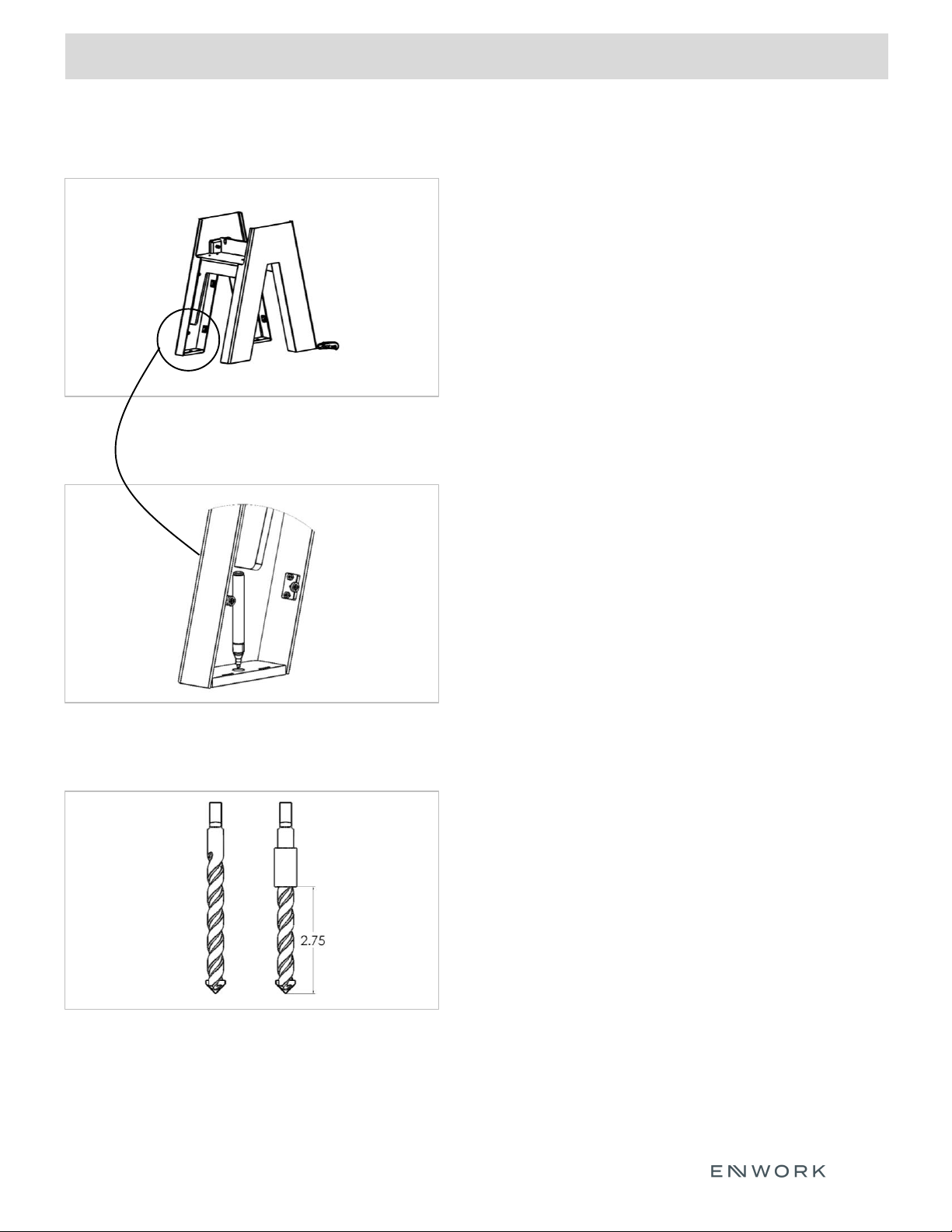
Fig. 3.1
Fig. 3.2
Fig. 3.3
3.1.1) Place base in final location for installation
3.1.2) Using a utility knife, cut away carpet in the four
leg locations.
3.1.3) Once all four leg location carpet cuts are
complete, move base and remove cut carpeting.
Note: Base must sit directly on concrete floor.
3.2.1) With carpet removed, replace the base in it’s
final position on the concrete.
3.2.2) Using a permanent marker, mark the anchor
hole locations.
Note: Hold the marker vertically and
spin the marker around the hole to get
the best result.
3.3.1) Measure 2 ¾” from the bottom of the ½”
diameter concrete drill bit and wrap drill bit with
tape creating a visual depth gauge.
Installing the Base continued

3) Assembly:
INSTALLATION INSTRUCTION
10
Fig. 3.4
Fig. 3.5
Fig. 3.6
3.4.1) Remove the base.
3.4.2) Drill marked hole locations to 2 ¾” deep.
3.4.3) Vacuum out the drilled holes to remove
dust that may prevent anchor from seating
properly.
3.5.1) Replace the base over final location.
3.5.2) Check that base is level. If base is level in two directions
skip to step 3.6.
3.5.3) If base is not level, use the included shims and place
shims on the outer corners as shown in Fig 3.5 until base
is level in two directions.
3.6.1) Place one washer and one hex nut onto
provided concrete anchor so that the hex nut is
flush with the top of the anchor.
3.6.2) Insert anchor with washer and nut through the
Base hole into the drilled floor hole. Using a hammer
or mallet pound anchors into drilled holes until anchor
washer and hex nut make contact with the base foot pad.
3.6.3) Use ¾” socket to tighten anchor hex nuts.
3.6.4) Double check all anchor hex bolts to ensure they are
tight.
Installing the Base continued

3) Assembly:
INSTALLATION INSTRUCTION
11
Fig 4
Installing Top Supports

3) Assembly:
INSTALLATION INSTRUCTION
12
Fig. 4.1
4.1.1) Left side top support shown.
Fig. 4.3
4.3.1) Loosely thread qty 1: ½” – 13 hex nut
onto the base pivot bolt.
4.3.2) Loosely thread qty 2: 3/8”-16 x 1 ½”
flange bolts with flat washers through the
bottom top support slot holes into the base
top plate.
4.3.3) Loosely thread qty 1: 3/4”-10 x 1 ¼” hex bolt
into the top support hex nut.
4.3.4) Repeat for all four top supports.
Note: Do not tighten any hardware yet.
Installing Top Supports continued
Fig. 4.2
4.2.1) Place top support on base top plate.
4.2.2) Slide top support towards the side wall
of base so that the pivot hole on the top
support slide onto the pivot bolt on base.
Note: Top support arms will slope downward from
the base. Leveling of top support arms is
done in the following steps.
Fig. 4.4
4.4) Tie plate and spacer layout.
4.5) Notch side up.
MID TIE PLATE
CENTER TIE PLATE
CENTER SPACER
END TIE PLATE
3) Assembly:
INSTALLATION INSTRUCTION
13
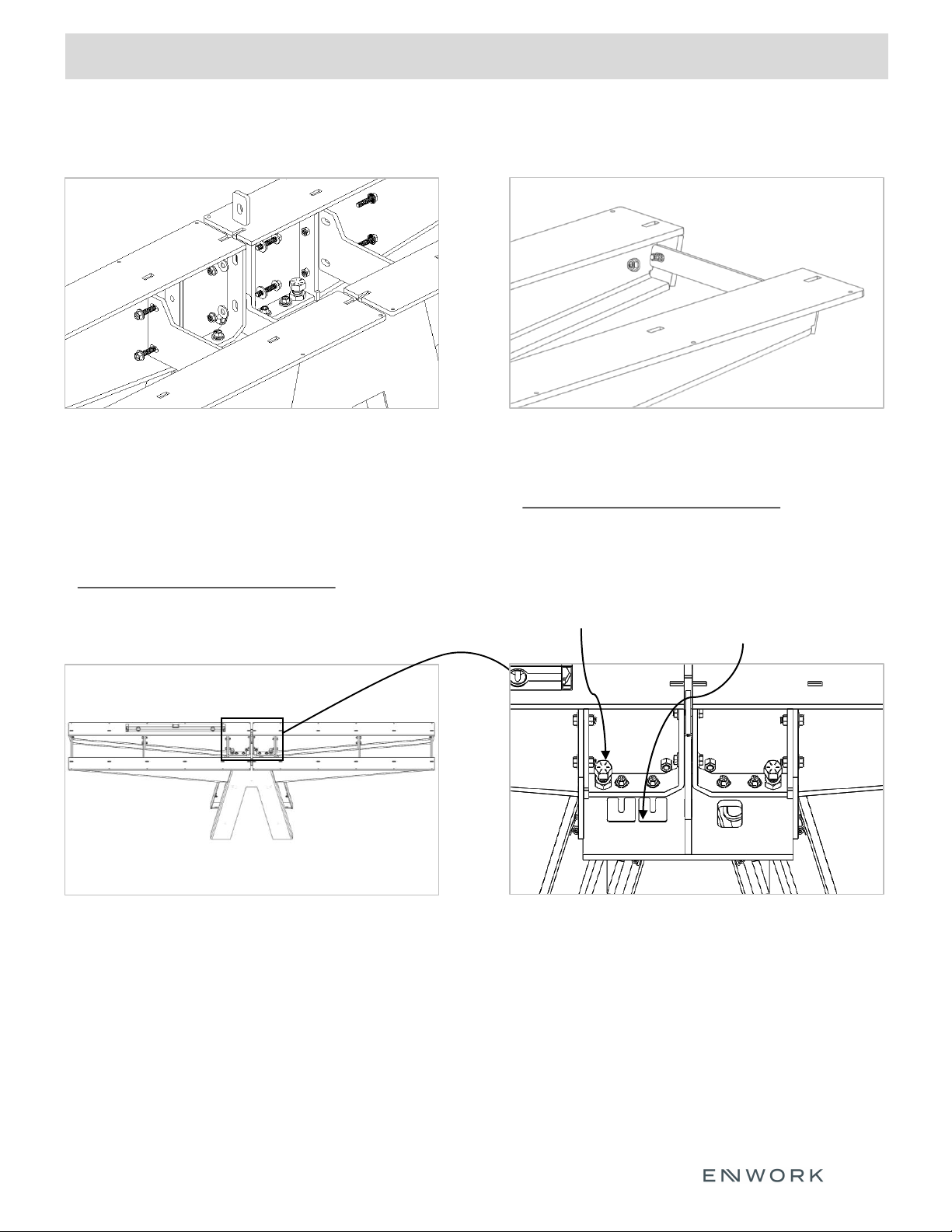
Fig. 4.5
4.5.1) Loosely install 3/8”-16 x 2” flange hex bolts
with flat washers, both sides and 3/8”-16
flange hex nut through both top supports and
center spacer.
4.5.2) Loosely install 3/8”-16 x 1 ½” flange hex bolts
through tie plates into top support bolt plates.
Note: Do not tighten any hardware yet.
Fig. 4.7
4.7.1) Using an adjustable wrench, turn the
¾” hex leveling bolt to clockwise to raise
the top support arm to level.
4.7.2) Once top support is level, use a combination
of different shim thicknesses to fill the gap
between the bottom of the top support arm
and base top plate.
Installing Top Supports continued
Fig. 4.6
4.6.1) Loosely install 3/8”-16 flange nut onto end tie
plate bolt.
Note: Do not tighten any hardware yet.
Fig. 4.8
4.7.3) With shims in place, turn the leveling bolt
counter clockwise to lower the arm onto the
shims.
4.7.4) With arm resting on shims, check level. If
arm dropped below level, raise arm with
leveling bolt and add more shims.
Hex leveling bolt Shim

3) Assembly:
INSTALLATION INSTRUCTION
14
Fig. 4.9
4.9.1) Push shims under the top support arm as far as
as they will go for full support.
Note: Sandwich thinner shims between thicker shims
to help prevent binding when pushing shims
under arm.
Note: Weight of top support arm must be sitting on
shims, not the leveling bolt. Ensure leveling
bolt is not under load.
Fig. 4.11
4.11.1) With arm level, tighten only the bolts
indicated in Fig. 4.11 on all arms.
Note: Order of operation when tightening bolts is
critical to the level of the top support arms.
Installing Top Supports continued
Fig. 4.10
4.10.1) Level top support arms front to back at the
at the end of the arm as shown in Fig. 4.10.
Fig. 4.12
4.12.1) With all arms level, use shims as shown
in Fig. 4.12 to fill the gap between center
spacers and top support arms.
Tighten

3) Assembly:
INSTALLATION INSTRUCTION
15
Fig. 4.13
4.13.1) Measurement between arms should be 10”.
Fig. 4.15
4.15.1) Install trough end cap and covers to ensure
fit between top support arms.
4.15.2) Trough cover flange sits on the bottom of
the top support arm.
4.15.3) Peel double sided tape backer from trough
end cap flange. Align outside face
of end cap to end of top support arms and
adhere to top support arm flange.
Note: Adhesive tape needs pressure during
application to achieve a strong bond.
Installing Top Supports continued
Fig. 4.14
4.14.1) Looking down the edge of the table, ensure
that top supports are straight.
Note: Ensure arms are straight, non aligned arms
will cause issue with trough installation.
Fig. 4.16
4.16.1) With top support arms level and straight
tighten tie plate bolts and center spacer
bolts.
10”
Tighten
3) Assembly:
INSTALLATION INSTRUCTION
16
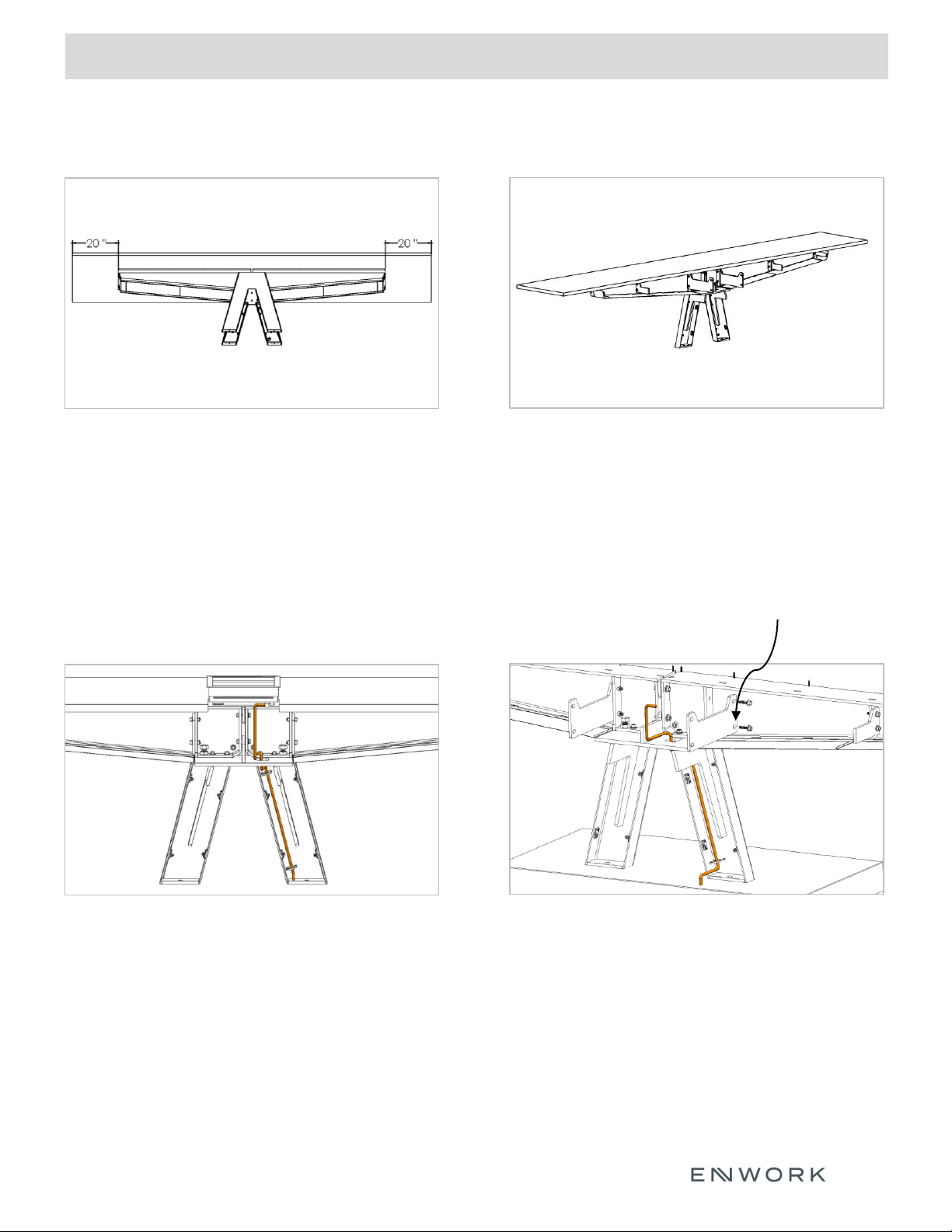
Fig. 5.1
5.1.1) Center surface on base. For multi piece tops,
attach tight joint fasteners.
Fig. 5.3
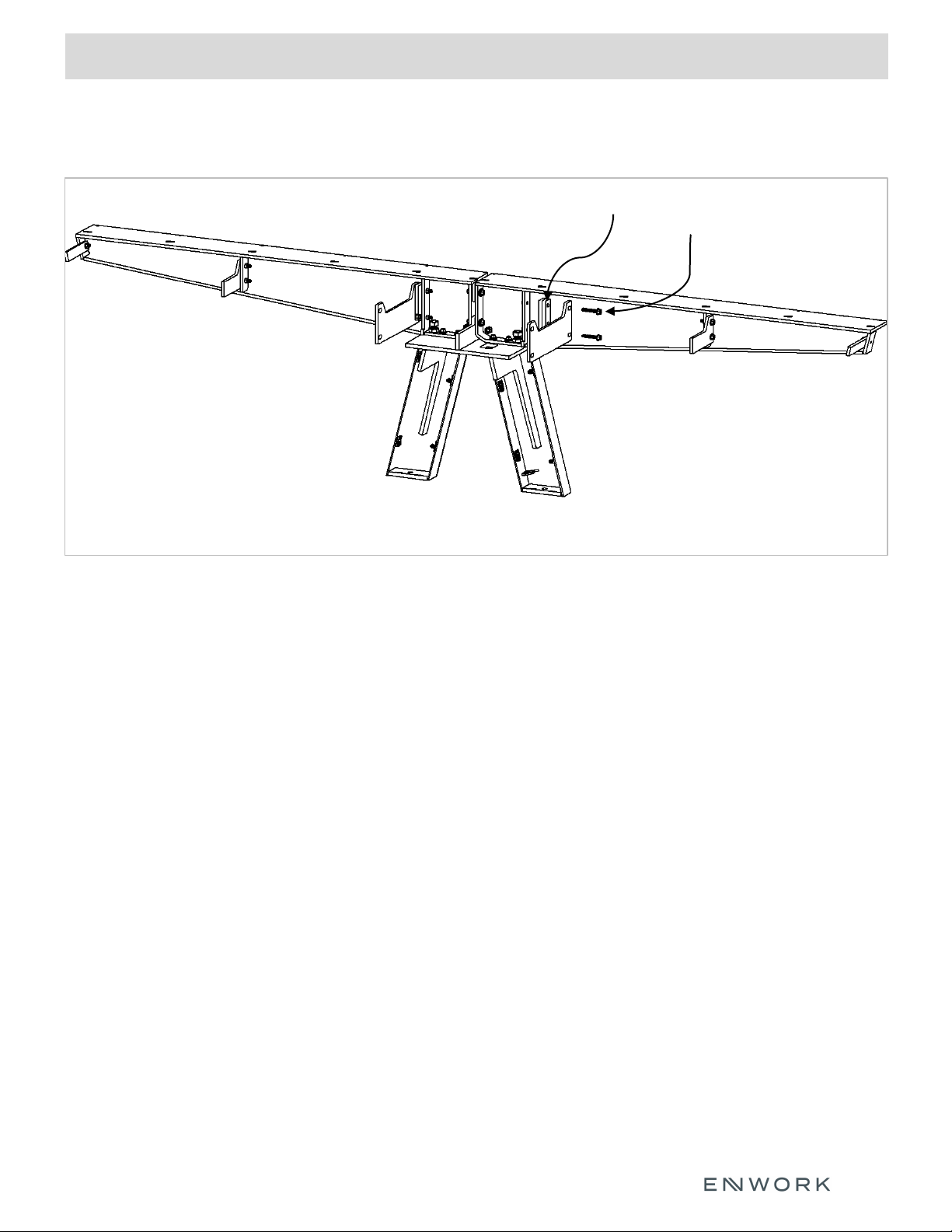
5.3.1) Power / Data routes thru base top plate
cutout.
5.3.2) Power / Data cables are held in right side
of leg with integrated hooks.
Installing surface and power
Fig. 5.2
5.2.1) If surface has power and data cutouts
check that they are unimpeded by top
tie plates.
5.2.2) Secure surface to base using included
Screw 1.
Fig. 5.4
5.4.1) It may be necessary to remove the center
tie plate to access center power.
Remove the four center tie plate bolts by
turning them counter clockwise.
5.4.2) Replace center tie plate when done.
Center tie plate

3) Assembly:
INSTALLATION INSTRUCTION
17
Fig. 6.1
Fig. 6.2
Fig. 6.3
6.1) Fig. 6.1 is base with inner leg cover option.
6.2.1) Inside leg covers are installed by placing
the hook on the back of leg cover into the
slot at the base of the leg.
6.2.2) Preinstalled magnets hold the leg cover
in place.
6.3.1) Fig. 6.3 shows optional end cover.
6.3.2) Installs between base legs, attaches to preinstalled magnets.
6.3.3) Fig. 6.3 shows power routing hole down for power infeed
access outside of base.
6.3.4) If power access is inside the base, flip the end cover so that
routing hole is up.
Installing leg covers
Base leg slot Cover hook
Optional end cover
3) Assembly:
INSTALLATION INSTRUCTION
18
Fig 7.1
Fig 7.1) If an Oasis Mini power unit is installed over the base (EQV296 / EQV426 / EQT296 / EQT426 models
only). The Oasis Mini Extension kit must be used as shown. This extension kit allows the use of the
Oasis Mini attachment brackets to be used so that the power unit can be secured to the
work surface.
Optional Oasis Mini Extension Kit
Optional Oasis Extension Bars
3/8”-16 x 2 ¼” Flange Bolt

Other manuals for Equilibrium
2
Table of contents
Other Enwork Desktop manuals


Popular Desktop manuals by other brands


HP
HP Presario SR5400 - Desktop PC Guida alla risoluzione dei problemi e alla manutenzione

CompuLab
CompuLab IPC2 owner's manual

Lenovo
Lenovo ThinkCentre M78 manual

HP
HP dx7200 - Microtower PC Quick setup guide

Control Data
Control Data Cyber 170 Series Operator's guide

Euphonix
Euphonix Avid SC264 installation manual