EPAK DivKit VSAT Ri Series User manual
1
DivKit VSAT
Ri-Series DSi-Series
Marine Satellite Systems and Services
®
29.03.19 ID: 0123

Table of Contents
1 What is a Diversity Kit? ......................................................................................................................3
2 Contents..............................................................................................................................................3
3 Installing the EPAK VSAT DivKit........................................................................................................3
4 Using the VSAT DivKit........................................................................................................................4
4.1 Description of the operating elements on front plane........................................................................4
4.2 Description of the of the connectors on the back plane......................................................................5
4.3 Cabling the EPAK VSAT DivKit - regular scheme..................................................................................6
4.4 The integrated matching system - attenuating and amplifying .................................................7
4.4.1 The importance of matching............................................................................................................7
4.4.2 The attenuator-regulators................................................................................................................9
4.5 The integrated Ethernet Switch........................................................................................................10

3
1
1 What is a Diversity Kit?
In RF technologies, you talk about antenna diversity if you have two or more antennas for one transceiver. This is often necessary
to provide a seamless functionality while receiving or transmitting, or to increase the receiving quality.
The EPAK Diversity Kit is combining the free line of sight ranges of 2 antennas: once one antenna is blocked in sight, the other
antenna seamlessly takes over the satellite connection. This requires a high performance switching device, that can split and reroute
RF signals nearly immediately.
The VSAT DivKit is designed for combining all EPAK VSAT antennas.
2 Contents
Your delivery contains the following components:
1x EPAK 19" VSAT DivKit
2x F/TNC RG6 coaxial cable 1,5m
4x TNC/TNC RG6 coaxial cable, 1,5m
3x Ethernet patch CAT5e cable, 1m
1x 24V power supply
3 Installing the EPAK VSAT DivKit
For regular cabling scheme see 4.3 - A.
For advanced cabling scheme with lock modem see 4.3 - B.
Step 1 Check that all required components and cables are there.
Step 2 Place the VSAT DivKit in the rack or at its other nal place.
Rack mount: For ease of handling follow the installation through and x it only in the last step.
Step 3 Connect the RX and TX port of the trac modem with the TX MDM and RX MDM port of the DivKit using the sup-
plied coaxial F/TNC cables.
Step 4 Connect the RX out and TX out ports from the master ACU with the ANT1 RX and the ANT1 TX ports of the DivKit
with the supplied coaxial TNC/TNC cables.
Step 5 Repeat step 4 for the slave ACU and the respective ANT2 RX and ANT2 TX ports of the DivKit.
Step 6 Connect the modem, ACUs and the DivKit Switch ports with the supplied Ethernet patch cables. Choose the most
left Ethernet port, RJ45(7) in Fig. 2, to be the slave ACU WAN port, RJ45(6) to be the slave lock modem port, RJ45(5)
to be the trac WAN port of the trac modem, RJ45(4) to be the port for the master lock modem, RJ45(3) to be
the WAN port of the master ACU and RJ45(1) the port of the router for ships vessels network. RJ45(2) is a port for
miscellaneous use and normally remains unused.
NOTE: The choice for the LAN ports are only recommendations. It does not matter for functionality but it facilitates
orientation for support sta.
Step 7 Plug in the DC power jack of the supplied power adapter into the DC connector at the DivKit's rear side.
Step 8 Power up the modem and ACUs, at the beginning both lock LEDs of the DivKit should turn green. Afterwards it will
keep the state of the last run.
Step 9 Turn the rocker switch to AUTO. If the ACUs have connection to the antennas, and those have locked to the proper
satellite signal, both Lock LEDs will stay green.
Step 10 Now turn the rocker switch from AUTO to ANT2 and then to ANT1. You will see how rst Active LED ANT 2 turns on
and then LED ANT 1 turns on while LED ANT 2 is turning o.
Step 11 As the nal step the signal power levels of the two antennas have to be equalized in order to ensure seamless hand
over. This has to be done for both ways RX and TX. Please see chapter 4.4.2 for further information.
4
1
4 Using the VSAT DivKit
The VSAT DivKit comes in a robust 19" rack case, ideal for combining it with the EPAK ACUs in one rack. The
holes for xing it with screws in the rack, are on the far left and the far right side when you look from the front.
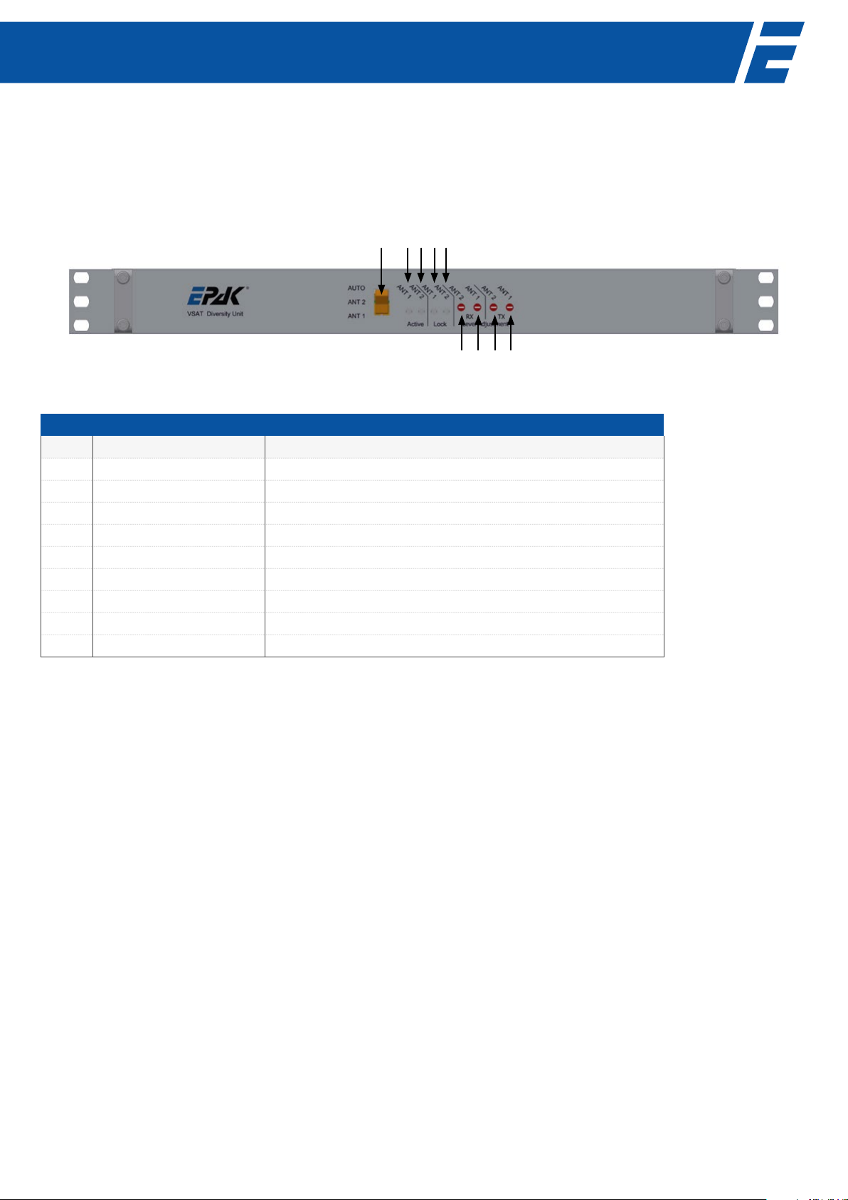
4.1 Description of the operating elements on front plane.
Fig. 1: EPAK VSAT-DivKit - front panel view.
Explanation
No. Name Description
1 Rocker switch Rocker switch for switching between AUTO, ANT2 and ANT1.
2 Active ANT1 LED Turns green if antenna 1 (master) is active (used for connection).
3 Active ANT2 LED Turns green if antenna 2 (slave) is active (used for connection).
4 Lock ANT1 LED Indicates "lock" state on antenna 1 (master).
5 Lock ANT1 LED Indicates "lock" state on antenna 2 (slave).
6 Attenuator RX2 16 step rotary switch for attenuating the RX2 (slave) signal path.
7 Attenuator RX1 16 step rotary switch for attenuating the RX1 (master) signal path.
8Attenuator TX2 16 step rotary switch for attenuating the TX2 (slave) signal path.
9Attenuator TX1 16 step rotary switch for attenuating the TX1 (master) signal path.
Tab. 1: Description of the operating elements on the front plane.
1 2 3 4 5
6 7 8 9

5
4.2 Description of the of the connectors on the back plane.
Fig. 2: EPAK VSAT-DivKit - back panel view.
Explanation
No. Name Description
1 RJ45(1) Ethernet port 1, recommended for ship's LAN
2 RJ45(2) Ethernet port 2, recommended to be spare
3 RJ45(3) Ethernet port 3, recommended to connect to WAN port of the master ACU
4 RJ45(4) Ethernet port 4
5 RJ45(5) Ethernet port 5, recommended to connect with trac modem
6 RJ45(6) Ethernet port 6
7 RJ45(7) Ethernet port 7, recommended to connect to WAN port of the slave ACU
8ANT1 TX TX signal output to antenna 1 (master)
9 TX MDM TX signal input coming from trac modem
10 ANT2 TX TX signal output to antenna 2 (slave)
11 DC power in Input for 24V power supply
12 ANT1 RX RX signal input from antenna 1 (master)
13 RX MDM RX signal output going to trac modem
14 ANT2 RX RX signal input from antenna 2 (slave)
Tab. 2: Description of the connectors on the back.
1 102 3 4 5 6 7 8 11 12 13 149
6
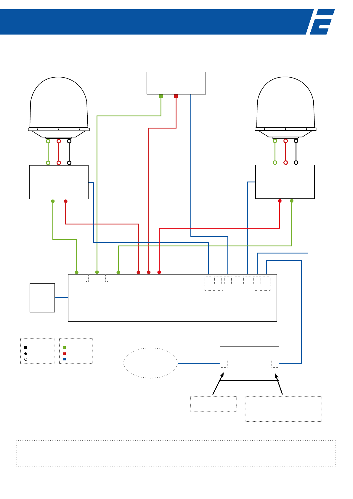
4.3 Cabling the EPAK VSAT DivKit - regular scheme
RX TX DC
RX TX DC
Traffic Modem
TX LAN
RX
ACU
TXRX
LAN 2
LAN 1 RX TX DC
WAN
ACU
TX RX LAN 2
LAN 1
RX TX DC
WAN
ANT2 RX
RX
ANT1 RX
ANT2 TX
TX
ANT1 TX
ROUTER
Spare
WANLAN
LAN
IP: 192.168.100.1
WAN
IP: <IP of Trac modem> +3
GW: <IP of Trac modem> +3
Netmask: <IP of Trac modem> +3
Connectors:
F-type
TNC male
N male
Colours:
Rx
Tx
IP
Ethernet ports
Diversity Kit
Switch Unit
192.168.2.254 192.168.1.254
192.168.2.254
192.168.1.254
Slave
antenna
Master
antenna
Vessel's
Network
(e.g. 192.168.100.0/24)
Fig. 3 A: Cabling scheme of VSAT DivKit
Notes:
• Trac modem needs minimum /29 netmask, a /30 contains only 2 hosts.
• Internet access is also possible from LAN1 or LAN2 on both Master and Slave ACU (DHCP available by default)
• All IP addresses shown here are examples
24 VDC
Power
Supply Unit
2 14 357 6

7
4.4 The integrated matching system - attenuating and amplifying
4.4.1 The importance of matching
Sometimes in systems with two antennas one of them has a much longer connection cable for receiving and transmitting. So the
signal from the antenna with the longer cable has a higher attenuation than the other one, which leads to dierent power levels
at the inputs of the trac modem and the TX input of the antenna.
Furthermore it is normal that antennas have dierent output power levels as well as input sensitivities, even if they are struc-
turally identical. This can cause errors like short lockouts of the trac modem or over powering the transceiver. To match these
dierent power levels, the VSAT DivKit has four power regulators attenuating from -15dB to amplifying to +15dB: one for each
RX line and one for each TX line. You can adjust the power levels in a resolution of 16 steps of 2dB each, where "0" corresponds to
15dB amplication and 16 corresponds to 15dB attenuation. The following examples describe situations where it is necessary to
use the power regulators.
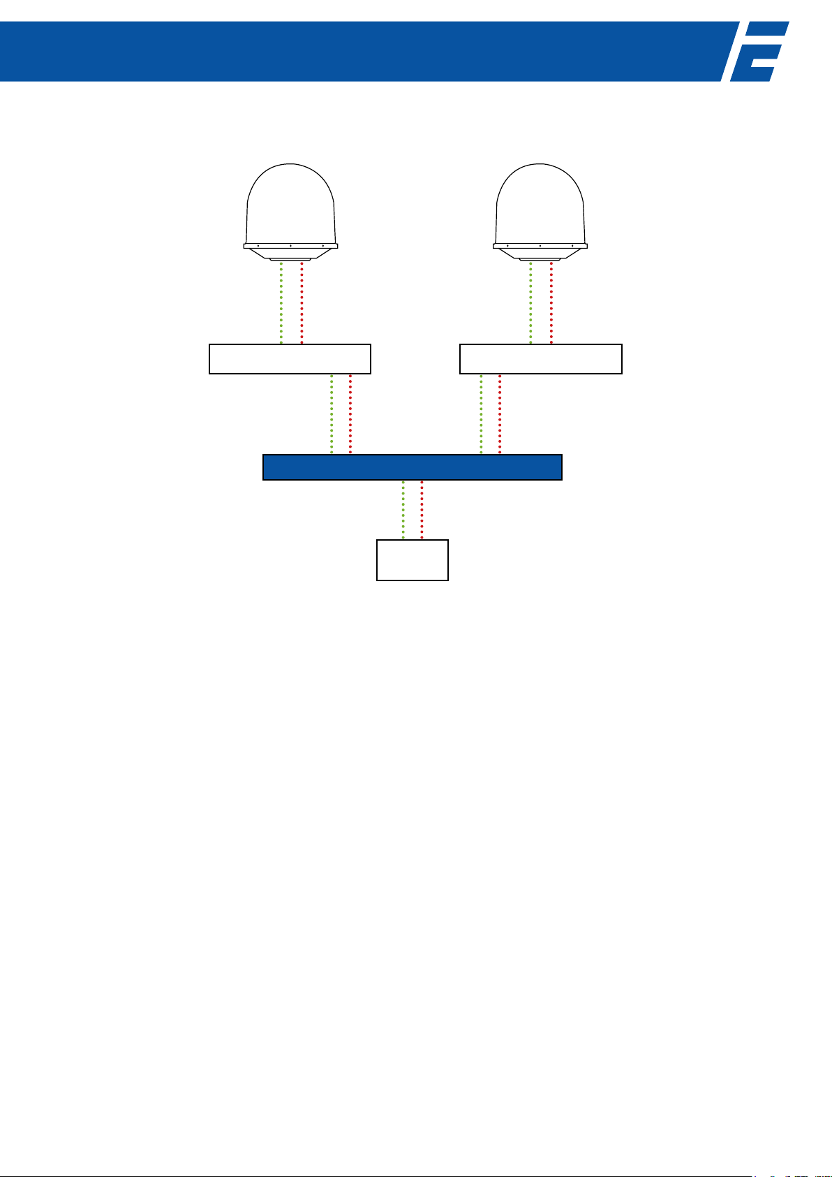
Explanation: Fig. 4 shows an example of mismatching RX power levels. Antenna 1 has an RX power output level of about -30dBm
and antenna 2 has an RX power output level of about -20dBm.
Antenna 1 is currently online. When the VSAT DivKit switches to antenna 2, the power at the modem suddenly jumps from -30 to
-20 dBm. Because the modem has to re-adjust its tuner for the new input level, the connection to the network will be intermittent
for a short time. In this example, the power regulator switches for RX1 of the VSAT DivKit needs to be adjusted to 10dB attenuati-
on to match the power level of the antenna 2.
Now both RX levels have -30dBm at the modem input.
Fig. 4: Example for the mismatching power levels of RX at the inputs of the modem.
ACU 2
EPAK DIVERSITY KIT
Modem
ACU 1
RX power: -30dBmRX power: -20dBm
TX1
RX1
TX2
RX2
TX1
RX1
TX2
RX2
No matching at power regulators
TX
RX
arrriving power level:
-20dBm for RX2
-30dBm for Rx1
Antenna 1Antenna 2
8
Explanation: Fig. 5 shows dierent TX power levels arriving the transceiver.
Because of dierent cable lengths, the cable loss for antenna 1 is higher than for antenna 2. The modem is driving currently
-10dBm on the TX line and antenna 1 is online. The arriving TX power at the BUC is now -20dBm, which is below the 1dB compres-
sion point of -15dBm. Now the VSAT DivKit switches to antenna 2. The cable to antenna 2 has only a loss of 5dB which means that
with a TX power of -10dBm the arriving TX power at the BUC input is about -15dBm.
This is exactly the 1dB suppression point of the antenna. If the Uplink Power Control (ULPC) sends a command to the modem to
increase the TX power (because of bad weather for example), the antenna works beyond the compression point and the signal
is distorted. That reduces the C/N value and ULPC sends a command to increase the TX power once more which reduces the C/N
value again.
To avoid this loop, you can turn the power regulator for TX2 to 6dB attenuation.
Now the arriving power at both antennas is equally at -20dBm.
Measuring the arriving TX power
Normally, the output power of the modem is regulated by the UPLC (Up Link Power Control) of your satellite service. It monitors
the arriving power level at the HUB and sends the modem the command to increase or decrease the output power.
Two antennas usually means dierent cable lengths and hence dierent arriving TX power levels at the input of the transceiver of
the antenna. The transceiver itself is not able to output the arriving TX power to the system, and so you have to request the UPLC
for the incoming power level at the HUB. When you know the corresponding values for both antennas, it is highly recommended
to match these power levels to avoid missing TX power margins, or even worse, saturation of one transmitter.
Fig. 5: Example for mismatching power levels of TX at the output of the modem.
ACU 2
EPAK DIVERSITY KIT
Modem
ACU 1
Arriving TX power: -20dBm
Cable loss: 10dB
TX power: -10dBm
Antenna 1Antenna 2
Arriving TX power: -15dBm
Cable loss: 5dB
Compression Point:
-15dBm
Compression Point:
-15dBm
TX1
RX1
TX2
RX2
TX1
RX1
TX2
RX2
TX
RX

9
4.4.2 The attenuator-regulators
For matching the dierent power levels of both antennas, four pieces of 16 step rotary switches are located at the front panel of
the VSAT DivKit. This is often necessary for matching the signal power of both antennas to avoid lockouts or signal loss like de-
scribed above. There are two switches for the two receive lines and two for the two transmit lines. You can nd them on the front
plane of the VSAT DivKit right next to the lock LEDs. (Fig. 6).
To adjust the rotary switches, take a long slotted screwdriver and carefully turn it around like shown in Fig. 6.
You can now switch from -15dB to +15dB (from 15dB attenuation to 15dB amplication). Each regulator is divided into 16 posi-
tions (0 – F). By turning clockwise, you lower the selected power level to the modem at a rate of 2dB per click/position. To nd out
which position the regulators currently have, look directly into the hole and you see the numbers around the screw.
The table on the next page shows the values you can select.
Fig. 6: Using the attenuators with a slotted screwdriver.
ANT1 TX
ANT2 TX
ANT1 RX
ANT2 RX

10
4.5 The integrated Ethernet Switch
For providing necessary network connections, the DivKit has an integrated network switch. The DivKit itself is connected to it too,
inside. There are seven RJ45 ports on the backplane: two for the ACUs, one for the trac modem, one for the ships LAN and three
for miscellaneous use. It does not matter which RJ45 jack you use for the dierent components, you can use either one, but it is
recommended to use the suggested cabling scheme, because it makes it more remote-manageable.
Rotary Switch
in HEX num No. Suppression/
Amplifying in dB
0 0 15 amplifying
1 1 14 amplifying
2 2 12 amplifying
3 3 10 amplifying
4 4 8 amplifying
5 5 6 amplifying
6 6 4 amplifying
7 7 2 amplifying
8 8 0
9 9 -2 attenuation
A 10 -4 attenuation
B 11 -6 attenuation
C 12 -8 attenuation
D 13 -10 attenuation
E 14 -12 attenuation
F 15 -15 attenuation
Tab. 3: Adjustable power levels
This manual suits for next models
1
Table of contents
Popular Marine Equipment manuals by other brands


Yacht Devices
Yacht Devices YDNB-07N user manual

Beijer Electronics
Beijer Electronics X2 control installation manual

Simrad
Simrad SR15 installation manual

Raymarine
Raymarine A series installation instructions

JRC
JRC JFE-680 - instruction manual

Kenwood
Kenwood KMR-700U - Radio / Digital Player instruction manual